EP2113305A2 - Dispositif de broyage - Google Patents
Dispositif de broyage Download PDFInfo
- Publication number
- EP2113305A2 EP2113305A2 EP09005992A EP09005992A EP2113305A2 EP 2113305 A2 EP2113305 A2 EP 2113305A2 EP 09005992 A EP09005992 A EP 09005992A EP 09005992 A EP09005992 A EP 09005992A EP 2113305 A2 EP2113305 A2 EP 2113305A2
- Authority
- EP
- European Patent Office
- Prior art keywords
- rotor
- crushing device
- feed
- housing
- crushing
- Prior art date
- Legal status (The legal status is an assumption and is not a legal conclusion. Google has not performed a legal analysis and makes no representation as to the accuracy of the status listed.)
- Withdrawn
Links
Images




Classifications
-
- B—PERFORMING OPERATIONS; TRANSPORTING
- B02—CRUSHING, PULVERISING, OR DISINTEGRATING; PREPARATORY TREATMENT OF GRAIN FOR MILLING
- B02C—CRUSHING, PULVERISING, OR DISINTEGRATING IN GENERAL; MILLING GRAIN
- B02C18/00—Disintegrating by knives or other cutting or tearing members which chop material into fragments
- B02C18/06—Disintegrating by knives or other cutting or tearing members which chop material into fragments with rotating knives
- B02C18/16—Details
- B02C18/22—Feed or discharge means
- B02C18/2225—Feed means
- B02C18/2291—Feed chute arrangements
-
- B—PERFORMING OPERATIONS; TRANSPORTING
- B02—CRUSHING, PULVERISING, OR DISINTEGRATING; PREPARATORY TREATMENT OF GRAIN FOR MILLING
- B02C—CRUSHING, PULVERISING, OR DISINTEGRATING IN GENERAL; MILLING GRAIN
- B02C18/00—Disintegrating by knives or other cutting or tearing members which chop material into fragments
- B02C18/06—Disintegrating by knives or other cutting or tearing members which chop material into fragments with rotating knives
- B02C18/14—Disintegrating by knives or other cutting or tearing members which chop material into fragments with rotating knives within horizontal containers
-
- B—PERFORMING OPERATIONS; TRANSPORTING
- B02—CRUSHING, PULVERISING, OR DISINTEGRATING; PREPARATORY TREATMENT OF GRAIN FOR MILLING
- B02C—CRUSHING, PULVERISING, OR DISINTEGRATING IN GENERAL; MILLING GRAIN
- B02C18/00—Disintegrating by knives or other cutting or tearing members which chop material into fragments
- B02C18/06—Disintegrating by knives or other cutting or tearing members which chop material into fragments with rotating knives
- B02C18/16—Details
- B02C18/18—Knives; Mountings thereof
- B02C2018/188—Stationary counter-knives; Mountings thereof
Definitions
- the present invention relates to a comminution device with a rotor rotating in a housing and having a comminuting blade.
- Such comminution devices are used for the comminution of waste of various kinds and have already become known in various forms.
- FIG. 1 shows the DE 91 09 063 U1 a crushing device with a rotor rotating in a housing and crushing blade-bearing rotor, wherein the rotor cooperates with a stator blade mounted on the housing and the lateral surface of the rotor is free of striking tools.
- an introduction region for the material to be comminuted is formed, in which the stator blade is arranged.
- the feed wall is inclined towards the rotor in the introduction region and, in the lower section of the introduction region, a catchment region which tapers in a wedge-shaped manner downwards is formed.
- the material to be crushed moves only by the inclination of the feed wall, the influence of gravity and the rotation of the rotor to the stator blade, wherein the introduction region has no feed slider or the like.
- the in the DE 91 09 063 U1 The crushing device shown has no perforated screen, which would limit the size of the material leaving the crushing device upwards. Instead, the material can be ejected freely down.
- the DE 91 09 063 U1 Although therefore comes in the insertion without a feed gate or the like, but has the problem that the material leaving the crushing device due to the lack of a perforated screen can be partially undesirable large.
- a crushing device which has a rotor rotating in a housing and crushing blade-bearing rotor, wherein the rotor cooperates with a stator blade mounted on the housing.
- an introduction region for the material to be comminuted is formed, in which the stator blade is arranged.
- Below the rotor is a perforated screen.
- the feed wall extends in the introduction region to the rotor inclined and it is in the lower portion of the introduction a downwardly wedge-shaped tapered catchment area formed, to which the perforated screen in Direction of rotation of the rotor considered followed.
- the DE 32 09 061 A1 does not require a feeding slide or the like in the introduction area and the arrangement of a perforated screen ensures that the material leaving the comminution device does not exceed a certain upper size.
- the use of impact tools only brings the desired effect to certain materials to be shredded.
- the impact is also associated with undesirable noise and the impact tools are wear elements, which limit the life of the rotor in an undesirable manner.
- From the AT 398 712 B shows a crushing device, with a rotatable in a housing and crushing blade-bearing rotor, which cooperates with a mounted on the stator stator, the lateral surface of the rotor is free of impact tools and wherein between a housing arranged on the feed wall and the rotor, an insertion region for is formed crushing material in which the stator blade is arranged. Below the rotor, a perforated screen is arranged below the rotor.
- the feed wall extends in the introduction region to the rotor inclined and it is in the lower portion of the introduction a downwardly wedge-shaped tapered catchment area formed, followed by the perforated screen in the direction of rotation of the rotor considered.
- a feed slider For transporting the material to be shredded in the direction of the stator blade, a feed slider is provided.
- the object of the invention is to provide a crushing device, which is provided on the one hand with a perforated screen to limit the size of the material leaving the crushing device upwards and on the other hand has a rotor whose outer surface is free of impact tools, said crushing device being structurally simpler should, as the previously known in the art comminution devices.
- the invention has thus recognized that it is in the in the AT 398 712 B It is not necessary to provide a feed gate, except that the material to be shredded is already moving towards the stator blade only by the inclination of the feed wall, the influence of gravity and the rotation of the rotor, although this is inherent in the arrangement of the perforated screen and the fact in that as a result the material which has passed through the stator knife can not fall freely downwards and therefore a certain resistance to the material falling from above is not to be expected.
- the angle ⁇ between the plane W in which the feed wall extends and a plane E extending vertically through the center of the rotor is less than 45 °.
- the angle ⁇ may be in a range of about 20 ° to about 30 °.
- the stator blade may be attached to the feed wall. This is particularly advantageous if it is provided that the Zuzhouwand is pivotally mounted and is acted upon by a force accumulator with a predetermined force against pivoting. In this case, the stator blade is reliably protected by the pivoting of the feed wall from damage to a material that has entered and is comminuted in the comminution device.
- the maximum speed of the rotor is less than 250 revolutions per minute.
- the comminution device according to the invention is thus advantageously a slowly rotating rotor.
- a toothed belt For slip-free power transmission of the driving force from an electric motor to the rotor, a toothed belt may be provided.
- a reinforcement of the self-insertion tendency results when it is provided that the lateral surface of the rotor is formed prismatic.
- FIGS. 1 to 6 Further advantages and details of the invention are the FIGS. 1 to 6 and the associated figure description removable.
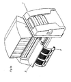
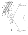
- FIG. 1a shows an embodiment of a crushing device 1 according to the invention in a perspective view with closed housing.
- Fig. 1b shows the same view, but with the housing 2 open and swung-out perforated screen. 7
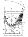
- the Fig. 2 provides a sectional view to Fig. 1 and shows the internal structure of the crushing device 1.
- a rotor 3 is rotatably mounted about its longitudinal axis.
- the rotor 3 carries a plurality of crushing blades 4, which cooperate with a mounted on the housing 2 stator blade 5.
- the material to be shredded can be introduced into the housing 2 via a feed hopper 8.
- the feed wall 9 extends in the introduction region to the rotor 3 inclined and forms due to their inclination in the lower portion of the introduction together with the rotor 3 a downwardly wedge-shaped tapered catchment area, in which the material to be crushed only by the inclination of the feed 9th , the influence of gravity and the rotation of the rotor 3 (in Fig. 2 in a clockwise direction) towards the stator blade 5.
- the stator blade 5 is directed in the operating state of the crushing device 1 to a region above the central axis of the rotor 3 out.
- the stator blade 5 is detachably attached to the feed wall 9.
- a perforated screen 7 is arranged, which only allows the passage of material up to a certain size. Material which is small enough to pass the perforated screen 7, falls into the discharge hopper 10 and a collecting area 11. In the collection area 11, a conveyor belt for removing the crushed material may be arranged. Larger material is transported by the rotation of the rotor 3 to a housing-fixed counter blade 6. The counter knife 6 is detachably attached to the housing 2.
- an electric motor 12 For driving the rotor 3, an electric motor 12 is provided.
- a toothed belt may be provided, since this allows, in contrast to conventional belt drives, a power transmission without slippage.
- the rotor is slowly running and rotates during operation with a number of revolutions of less than 250 revolutions per minute. For example, a speed of 150 revolutions per minute can be provided.
- the Diseinzugs need is reinforced by the here prismatic design of the lateral surface of the rotor 3.
- the rotor preferably has a relatively large diameter of, for example, more than 80 cm.
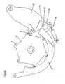
- the stator blade 5 supporting feed wall 9 is formed swing-out in this embodiment (see, for example Fig. 3 ).
- the feed wall 9 is acted upon by a force accumulator 13 with a predetermined force against pivoting.
- the energy storage device 13 contacts the feed wall 9 via interchangeable stops 14, 15.
- the execution of the contact points between the energy storage 13 and the feed 9 as releasably secured stops 14, 15 allows easy replacement of these wear parts.
- the perforated sieve 7 can be pivotally mounted to allow access to the rotor 3 from below or the removal of material from the area between the rotor 3 and perforated sieve 7.
- Fig. 3 is still the arrangement of a working platform 17 next to the housing 2 of the crushing device 1 shows.
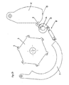
- the Fig. 4 shows the rotor 3 in a perspective detail view. From this, the type of attachment of the crushing knife 4 on the rotor 3 is apparent.
- the comminution knives 4 are fastened in each case to the rotor 3, in groups of three spaced-apart from one another tangentially to the direction of rotation, via separate knife carriers 18.
- the attachment is such that on the one hand radially extending support beams 19, which are braced in radially extending recesses of the rotor 3 and approximately tangentially to the direction of rotation extending paragraphs 20 are provided.
- the knife carrier 18 are formed approximately L-shaped in this embodiment, wherein one leg of the L's is mounted in mounting position on a support beam 19 and the other leg of L's rests on a shoulder 20.
- Fig. 4a Unlike in Fig. 4a is shown in a preferred variant ( Fig. 4b . Fig. 4c ) are provided, not to arrange the individual crushing 4 a group in a line, but with an offset to each other on the rotor 3.
- the entire length of the rotor 3 could not be as in Fig. 4a . 4b . 4c represented by three crushing knives 4, sondem example, be covered by up to eight Zerkiein ceremoniessmessern 4.
- each crushing knife 4 via a suitable number of screws 21 (here: six pieces), which run through the arranged on crushing 4 holes mounted on the knife carrier 18, wherein the screws 21 are secured by nuts 22.
- unit of crushing knife 4 and blade carrier 18 may advantageously be pre-assembled outside the crushing device 1 and attached as a unit via the screw 23 and the support beam 19 on the rotor 3.
- the crushing 4 other than known from the prior art not superscripted (that is, with the longest direction radially to the rotor 3), lying sondem (ie with the longest direction about tangential to the direction of rotation).
- This measure can be used independently of the other measures of the embodiment shown.
- Fig. 6 is a perspective detailed view of the perforated screen 7 forth.
- the holes of the perforated screen 7 need not necessarily be circular. It would be conceivable, for example, the formation of the holes as slots, which may extend substantially over the entire angular extent of the perforated screen 7.
- the crushing device in the illustrated embodiment is designed as a single-shaft shredder.
Landscapes
- Engineering & Computer Science (AREA)
- Food Science & Technology (AREA)
- Crushing And Pulverization Processes (AREA)
Applications Claiming Priority (1)
| Application Number | Priority Date | Filing Date | Title |
|---|---|---|---|
| AT0025508U AT10892U1 (de) | 2008-05-02 | 2008-05-02 | Zerkleinerungsvorrichtung |
Publications (2)
| Publication Number | Publication Date |
|---|---|
| EP2113305A2 true EP2113305A2 (fr) | 2009-11-04 |
| EP2113305A3 EP2113305A3 (fr) | 2017-04-19 |
Family
ID=40911913
Family Applications (1)
| Application Number | Title | Priority Date | Filing Date |
|---|---|---|---|
| EP09005992.4A Withdrawn EP2113305A3 (fr) | 2008-05-02 | 2009-04-30 | Dispositif de broyage |
Country Status (2)
| Country | Link |
|---|---|
| EP (1) | EP2113305A3 (fr) |
| AT (1) | AT10892U1 (fr) |
Cited By (7)
| Publication number | Priority date | Publication date | Assignee | Title |
|---|---|---|---|---|
| DE202012004224U1 (de) | 2011-05-04 | 2012-05-16 | Atm Recyclingsystems Gmbh | Rotorschere |
| DE102011119595A1 (de) * | 2011-11-29 | 2013-05-29 | Pallmann Maschinenfabrik Gmbh & Co Kg | Vorrichtung zum Zerkleinern von Aufgabegut |
| WO2013113989A1 (fr) * | 2012-01-30 | 2013-08-08 | Bmh Technology Oy | Broyeur |
| CN108380335A (zh) * | 2018-02-12 | 2018-08-10 | 曾玉凤 | 一种用于苗木枯枝的旋转式破碎装置 |
| WO2021074411A1 (fr) * | 2019-10-16 | 2021-04-22 | Siempelkamp Maschinen- Und Anlagenbau Gmbh | Appareil de broyage de charge d'alimentation fluide et procédé d'ouverture d'un tel appareil |
| US11484886B2 (en) | 2018-05-23 | 2022-11-01 | Vermeer Manufacturing Company | Shredder for comminuting bulk material |
| RU2797269C1 (ru) * | 2019-10-16 | 2023-06-01 | Зимпелькамп Машинен - Унд Анлагенбау Гмбх | Устройство для измельчения сыпучего загружаемого материала, а также способ открывания такого устройства |
Citations (3)
| Publication number | Priority date | Publication date | Assignee | Title |
|---|---|---|---|---|
| DE3209061A1 (de) | 1982-03-12 | 1983-09-22 | Kirchner GmbH & Co Spezialmaschinen, 7081 Essingen | Hackmaschine |
| DE9109063U1 (de) | 1990-07-28 | 1991-10-17 | Lescha Maschinenfabrik GmbH & Co KG, 8900 Augsburg | Häcksler |
| AT398712B (de) | 1989-08-30 | 1995-01-25 | Lindner Manfred | Restholzzerkleinerungsmaschine |
Family Cites Families (2)
| Publication number | Priority date | Publication date | Assignee | Title |
|---|---|---|---|---|
| DE2345214A1 (de) * | 1973-09-07 | 1975-03-20 | Fahr Ag Maschf | Zerkleinerungsvorrichtung |
| PT1050340E (pt) * | 1999-04-29 | 2004-04-30 | Lindner Recyclingtech Gmbh | Dispositivo de fragmentacao para material a ser fragmentado por accao de faca tendo um rotor montado numa caixa |
-
2008
- 2008-05-02 AT AT0025508U patent/AT10892U1/de not_active IP Right Cessation
-
2009
- 2009-04-30 EP EP09005992.4A patent/EP2113305A3/fr not_active Withdrawn
Patent Citations (3)
| Publication number | Priority date | Publication date | Assignee | Title |
|---|---|---|---|---|
| DE3209061A1 (de) | 1982-03-12 | 1983-09-22 | Kirchner GmbH & Co Spezialmaschinen, 7081 Essingen | Hackmaschine |
| AT398712B (de) | 1989-08-30 | 1995-01-25 | Lindner Manfred | Restholzzerkleinerungsmaschine |
| DE9109063U1 (de) | 1990-07-28 | 1991-10-17 | Lescha Maschinenfabrik GmbH & Co KG, 8900 Augsburg | Häcksler |
Cited By (10)
| Publication number | Priority date | Publication date | Assignee | Title |
|---|---|---|---|---|
| DE202012004224U1 (de) | 2011-05-04 | 2012-05-16 | Atm Recyclingsystems Gmbh | Rotorschere |
| DE102011119595A1 (de) * | 2011-11-29 | 2013-05-29 | Pallmann Maschinenfabrik Gmbh & Co Kg | Vorrichtung zum Zerkleinern von Aufgabegut |
| WO2013113989A1 (fr) * | 2012-01-30 | 2013-08-08 | Bmh Technology Oy | Broyeur |
| CN108380335A (zh) * | 2018-02-12 | 2018-08-10 | 曾玉凤 | 一种用于苗木枯枝的旋转式破碎装置 |
| US11484886B2 (en) | 2018-05-23 | 2022-11-01 | Vermeer Manufacturing Company | Shredder for comminuting bulk material |
| US11819856B2 (en) | 2018-05-23 | 2023-11-21 | Vermeer Manufacturing Company | Shredder for comminuting bulk material |
| US12330166B2 (en) | 2018-05-23 | 2025-06-17 | Vermeer Manufacturing Company | Shredder for comminuting bulk material |
| WO2021074411A1 (fr) * | 2019-10-16 | 2021-04-22 | Siempelkamp Maschinen- Und Anlagenbau Gmbh | Appareil de broyage de charge d'alimentation fluide et procédé d'ouverture d'un tel appareil |
| RU2797269C1 (ru) * | 2019-10-16 | 2023-06-01 | Зимпелькамп Машинен - Унд Анлагенбау Гмбх | Устройство для измельчения сыпучего загружаемого материала, а также способ открывания такого устройства |
| US12162021B2 (en) | 2019-10-16 | 2024-12-10 | Siempelkamp Maschinen-Und Anlagenbau Gmbh | Apparatus for comminuting pourable feedstock and method for opening such an apparatus |
Also Published As
| Publication number | Publication date |
|---|---|
| EP2113305A3 (fr) | 2017-04-19 |
| AT10892U1 (de) | 2009-12-15 |
Similar Documents
| Publication | Publication Date | Title |
|---|---|---|
| DE10006757C1 (de) | Verfahren und Vorrichtungen zum Zerkleinern von Spänen | |
| DE2516014A1 (de) | Zerkleinerungsmaschine fuer abfaelle | |
| EP1638702A2 (fr) | Tamiseur a tambour | |
| EP2113305A2 (fr) | Dispositif de broyage | |
| EP1899072B1 (fr) | Broyeur | |
| EP2537588A2 (fr) | Déchiqueteur avec lames à plusieurs tranchants | |
| DE102008039258A1 (de) | Zerkleinerungsmaschine | |
| DE4328506C1 (de) | Spänebrecher | |
| AT398712B (de) | Restholzzerkleinerungsmaschine | |
| EP0133436B1 (fr) | Installation de fragmentation et procede en particulier de production de copeaux de bois | |
| DE10350123B3 (de) | Häckselvorrichtung für einen Mähdrescher | |
| DE202010005584U1 (de) | Zerkleinerungsmaschine | |
| DE102016000323A1 (de) | Zerkleinerung von Festplatten | |
| DE3211823C2 (fr) | ||
| DE202010010958U1 (de) | Zerkleinerungsvorrichtung für Schüttgutpartikel | |
| DE2942751C2 (fr) | ||
| WO2018050809A1 (fr) | Rotor de hachage pour un dispositif de broyage, en particulier hachoir | |
| DE202007006712U1 (de) | Schrauben-Nachdrückeinrichtung für Zerkleinerungseinrichtung | |
| DE102014005328A1 (de) | Vorrichtung zur Zerkleinerung von stückigen Reststoffen der Palmölgewinnung | |
| AT504824A2 (de) | Zerkleinerungsvorrichtung | |
| AT374377B (de) | Vorrichtung zur zerkleinerung von landwirtschaftlichem gut | |
| DE894980C (de) | Rechengutzerkleinerer fuer Wasserreinigungsrechen | |
| DE3123484C2 (de) | Zerkleinerungsvorrichtung für faseriges Gut | |
| DE202011103394U1 (de) | Mühle zur Zerkleinerung von Mahlgut | |
| DE20309648U1 (de) | Zerkleinerungsanlage |
Legal Events
| Date | Code | Title | Description |
|---|---|---|---|
| PUAI | Public reference made under article 153(3) epc to a published international application that has entered the european phase |
Free format text: ORIGINAL CODE: 0009012 |
|
| AK | Designated contracting states |
Kind code of ref document: A2 Designated state(s): AT BE BG CH CY CZ DE DK EE ES FI FR GB GR HR HU IE IS IT LI LT LU LV MC MK MT NL NO PL PT RO SE SI SK TR |
|
| RAP1 | Party data changed (applicant data changed or rights of an application transferred) |
Owner name: ANTON UNTERWURZACHER MASCHINENBAUHOLDING GMBH |
|
| PUAL | Search report despatched |
Free format text: ORIGINAL CODE: 0009013 |
|
| AK | Designated contracting states |
Kind code of ref document: A3 Designated state(s): AT BE BG CH CY CZ DE DK EE ES FI FR GB GR HR HU IE IS IT LI LT LU LV MC MK MT NL NO PL PT RO SE SI SK TR |
|
| AX | Request for extension of the european patent |
Extension state: AL BA RS |
|
| RIC1 | Information provided on ipc code assigned before grant |
Ipc: B02C 18/22 20060101AFI20170314BHEP Ipc: B02C 18/14 20060101ALI20170314BHEP Ipc: B02C 18/18 20060101ALI20170314BHEP |
|
| STAA | Information on the status of an ep patent application or granted ep patent |
Free format text: STATUS: THE APPLICATION HAS BEEN PUBLISHED |
|
| STAA | Information on the status of an ep patent application or granted ep patent |
Free format text: STATUS: THE APPLICATION IS DEEMED TO BE WITHDRAWN |
|
| 18D | Application deemed to be withdrawn |
Effective date: 20171020 |