EP2113353A2 - Construction de la paroi latérale d'un moule de coulée - Google Patents
Construction de la paroi latérale d'un moule de coulée Download PDFInfo
- Publication number
- EP2113353A2 EP2113353A2 EP09397512A EP09397512A EP2113353A2 EP 2113353 A2 EP2113353 A2 EP 2113353A2 EP 09397512 A EP09397512 A EP 09397512A EP 09397512 A EP09397512 A EP 09397512A EP 2113353 A2 EP2113353 A2 EP 2113353A2
- Authority
- EP
- European Patent Office
- Prior art keywords
- construction
- magnet
- sidewall
- profile
- surface plate
- Prior art date
- Legal status (The legal status is an assumption and is not a legal conclusion. Google has not performed a legal analysis and makes no representation as to the accuracy of the status listed.)
- Granted
Links
Images


Classifications
-
- B—PERFORMING OPERATIONS; TRANSPORTING
- B28—WORKING CEMENT, CLAY, OR STONE
- B28B—SHAPING CLAY OR OTHER CERAMIC COMPOSITIONS; SHAPING SLAG; SHAPING MIXTURES CONTAINING CEMENTITIOUS MATERIAL, e.g. PLASTER
- B28B7/00—Moulds; Cores; Mandrels
- B28B7/0002—Auxiliary parts or elements of the mould
- B28B7/0014—Fastening means for mould parts, e.g. for attaching mould walls on mould tables; Mould clamps
- B28B7/002—Fastening means for mould parts, e.g. for attaching mould walls on mould tables; Mould clamps using magnets
-
- B—PERFORMING OPERATIONS; TRANSPORTING
- B28—WORKING CEMENT, CLAY, OR STONE
- B28B—SHAPING CLAY OR OTHER CERAMIC COMPOSITIONS; SHAPING SLAG; SHAPING MIXTURES CONTAINING CEMENTITIOUS MATERIAL, e.g. PLASTER
- B28B7/00—Moulds; Cores; Mandrels
- B28B7/0002—Auxiliary parts or elements of the mould
- B28B7/0014—Fastening means for mould parts, e.g. for attaching mould walls on mould tables; Mould clamps
- B28B7/0017—Fastening means for mould parts, e.g. for attaching mould walls on mould tables; Mould clamps for attaching mould walls on mould tables
-
- Y—GENERAL TAGGING OF NEW TECHNOLOGICAL DEVELOPMENTS; GENERAL TAGGING OF CROSS-SECTIONAL TECHNOLOGIES SPANNING OVER SEVERAL SECTIONS OF THE IPC; TECHNICAL SUBJECTS COVERED BY FORMER USPC CROSS-REFERENCE ART COLLECTIONS [XRACs] AND DIGESTS
- Y10—TECHNICAL SUBJECTS COVERED BY FORMER USPC
- Y10S—TECHNICAL SUBJECTS COVERED BY FORMER USPC CROSS-REFERENCE ART COLLECTIONS [XRACs] AND DIGESTS
- Y10S425/00—Plastic article or earthenware shaping or treating: apparatus
- Y10S425/033—Magnet
Definitions
- the present invention relates to a sidewall construction of a casting mold to be used in casting concrete elements, said sidewall construction comprising a support construction and a changeable mold surface plate. More precisely, the invention concerns a support construction of a sidewall construction comprising a magnetic fixing to the mold surface plate.
- Detachable sidewalls of casting molds for elements cast of concrete are known in the art, said sidewalls being equipped with different fixing solutions.
- the sidewalls can be positioned to the casting bed in desired places depending on the size and form of the product to be cast.
- the flat mold to be used is in general a table or a tipping mold equipped with sidewalls.
- a casting machine goes above the table and batches the concrete mix to the mold. After the concrete is hardened, the table is tipped about a tilting axle provided on one side of the table, into an almost upright position, the sidewall of the mold ending up to be the uppermost will be removed, and the element is lifted away from the table using lugs provided on its sides.
- the position of the upper sidewall must be movable depending on the size of the element to be cast, and for that purpose, removable sidewalls can be used.
- removable and adjustable sidewall parts also openings can be formed to the element in desired places.
- magnets for fastening removable sidewalls of the mold to the casting bed. Magnets are especially suitable for fixing a sidewall as they attach to the smooth steel surface of the casting bed. To provide a strong attachment of the sidewall, strong magnets must be used effecting bond strength of e.g. 15 kN.
- the sidewall construction of a casting mold in accordance with the present invention comprises a support construction and a changeable metallic mold surface plate to be fixed thereto by means of a magnet.
- the mold surface plate in this connection refers to a plate/part to be fixed to the support construction of the sidewall construction by means of a magnet, setting against the product to be cast and defining the outer surface of the product to be cast.
- a sidewall construction is provided being easily and inexpensively convertible for different production runs.
- the separate mold surface plate of the sidewall construction according to the invention is easily cleanable and conveniently storable.
- the invention also enables different and even most difficult shapes and inclinations to be fixed ready to the mold surface plate, and these constructions as ready stock items can be effectively changed, adjusted and continued.
- the invention concerns a sidewall construction of a casting mold for casting concrete elements, said sidewall construction comprising a mold surface plate defining the outer surface of the product to be cast and a support construction comprising at least one horizontal profile.
- the sidewall construction of the present invention is characterized by what is stated in the characterizing part of Claim 1.
- Figure 1A shows a cross sectional view of an example of one sidewall construction of a casting mold according to the invention, comprising a support construction consisting of one horizontal profile 1, at least one magnet 2 being located in said profile for fixing a mold surface plate 3.
- the construction of the horizontal profile is formed so as to accommodate the magnet 2 or magnets in said profile 1 so that the mold surface plate 3 attaches to the profile 1 by means of the magnet 2.
- the magnet 2 is kept in the profile 1 by means of shoulders 4 formed to the magnet 2. As shown in Figure lA, the shoulders 4 of the magnet come in close contact with the inner surface of an edge 5 of the horizontal profile 1 setting against the mold surface plate 3, when the mold surface plate 3 is fixed to the profile 1 by means of the magnet 2.
- the magnet 2 is located in a groove of the horizontal profile 1.
- the power, size and number of the magnets to be used must be designed so that the mold surface plate 3 is kept firmly fixed to the support construction by means of the magnet 2 during the casting process.
- the support construction comprises two horizontal profiles 1a and 1b and at least one vertical profile 6 connecting the same.
- the reference numeral 1 refers to a horizontal profile in general.
- Reference numerals 1a and 1b are used, when the supporting construction comprises a plurality of horizontal profiles (like in Figure 1B ) so that 1a refers to a lower horizontal profile and 1b to an upper horizontal profile.
- All the above mentioned horizontal profiles 1, 1a and 1b comprise a magnet 2 and have for that part a similar construction.
- the both horizontal profiles 1a and 1b comprise at least one magnet 2.
- the number of vertical profiles 6 depends on the length of the sidewall construction; the longer the sidewall construction is, the more vertical profiles 6 are needed for providing a support construction firm enough. Combining of the sidewall constructions according to the invention can be made quickly and simply, whereby the long edge of the casting mold can comprise a plurality of sequential sidewall constructions. In addition, different provisions like window and door openings can be easily arranged.
- Support construction formed of the profiles is preferably made of a form profile, especially advantageously of an aluminium profile.
- Vertical profiles 6 have preferably a form having an adequate depth in the transversal direction of the sidewall construction for providing a sufficient supporting effect for the eventual upper horizontal profile 1b, when the casting mold equipped with said sidewall constructions has been filled with concrete mix.
- the depth of the vertical profile 6 in the longitudinal direction of the sidewall construction is basically defined by the adequate internal stiffness of the support construction.
- the depth of the horizontal profiles 1 in the transversal direction of the sidewall construction is defined by the form of the vertical profiles. Fixing of the sidewall construction to the casting bed is effected by means of the horizontal profile 1. If the sidewall construction comprises more than one horizontal profile, the fixing of the sidewall construction is effected by means of the lower horizontal profile 1a.
- the support construction of the sidewall construction is formed of aluminium profiles, they are preferably piece goods, whereby the sidewall construction can easily be manufactured with a desired length and height by cutting the profiles into pieces with a desired length.
- the magnets 2 are located to the horizontal profile 1 or profiles 1a and 1b at suitable distances so, that the attachment of the mold surface plate 3 to the support construction is firm. In case required by the height of the mold surface plate 3 or some other circumstances, magnets 2 can also be located to a plurality of horizontal profiles 1a and 1b as shown in Figure 1B . This is usually the case, if the height of the mold surface plate 3 exceeds 300 mm.
- the size and form of the magnets 2 can also be defined e.g. by the form of the horizontal profile 1 or, on the other hand, the magnet space of the formed profile can have an appropriately designed form.
- the magnet space in this connection refers to that space or groove in the form profile and especially in the horizontal profile 1, where the magnet 2 or magnets is/are located.
- the size of the magnet 2 can vary, but typically it is about 40x40x100 mm.
- the adhesive force of the magnet 2 can also vary depending e.g. on the mutual distances of the magnets 2 both in horizontal and vertical direction, and on the construction of the mold surface plate and the surface properties thereof.
- the adhesive force of the magnet 2 can be e.g. about 2,5 kN.
- the magnets 2 are located in the horizontal profile 1 at certain distances, e.g. at distances of 200 to 2000 mm, preferably at distances of 800 to 1000 mm, in other words, the magnet 2 is discontinuous, which means that there is a plurality of them in one and the same horizontal profile 1. It is also possible that the magnet 2 is continuous along the whole length of the horizontal profile 1.
- the attachment of the magnet 2 to the horizontal profile 1 can be steppless, which means that the magnet can be moved lengthwise in the magnet space of the horizontal profile 1, i.e. in the groove, to a desired place according to need.
- a spring part attached to the back surface of the magnet 2 keeping the magnet firmly in place.
- the back surface of the magnet 2 refers to that surface of the magnet 2 that is located furthest from the mold surface plate 3.
- the spring part can be e.g. a sprung plastic pad pressing the magnet 2 against the inner surface of the edge 5 of the horizontal profile resting against the mold surface plate. Due to the steppless or sliding attachment, the magnet 2 can be removed from the horizontal profile 1, if necessary.
- the magnet 2 can be locked immovably in its place by extruding glue material to the lower part of the magnet space at the desired fixing place of the magnet.
- the mold surface plate 3 is made of metal, preferably of steel.
- the fixing surface of the mold surface plate 3 can have nodules, providing an especially firm and tight attachment to the support construction.
- the fixing surface refers to that surface of the mold surface plate 3 that comes against the support construction.
- the nodules are preferably formed so that they set to those places of the magnet space, i.e. groove, of the horizontal profile 1, that are without magnets 2.
- a mold surface plate with nodules allows the use of weaker magnets without loosing the firmness of the sidewall construction and thus facilitates the loosening of the mold surface plate 3 from the support construction.
- Figures 2A and 2B illustrate as a series of pictures one preferred embodiment of the present invention.
- Figure 2A shows the initial situation, where the magnet 2 is not yet attached to the mold surface plate 3.
- the mold surface plate is firmly and tightly attached to the magnet 2, and thus also to the support construction.
- the magnet 2 comprises a flexible side construction/flexible shoulders 7 setting against the inner surface of the edge 5 of the horizontal profile 1 resting against the mold surface plate 3. Due to the flexible side construction 7 of the magnet, it is possible to leave a gap 8 between the mold surface plate 3 and the magnet 2. This gap can be provided e.g.
- a flexible construction can also be provided to the surface (not shown in the figures) setting against the magnet, in other words to the inner surface of the edge 5 of the horizontal profile 1 resting against the mold surface plate 3 so, that flexible parts are attached to the points of said inner surface facing the shoulders of the magnet 2.
- the flexible material can be any material suitable for this purpose, like rubber.
- FIG 3 shows fixing of one mold surface plate 3 having an inclination 9 to the support construction in a sidewall construction according to the invention.
- the mold surface plate 3 is ready built so that it comprises the inclination 9.
- Said mold surface plate 3 is fixed to the support construction by means of at least one magnet 2 located in the horizontal profile 1.
- Figure 4 shows that it is simple to arrange also difficult forms in the sidewall construction according to the invention, like e.g. indentations 10.
- Figures from 5 to 8 show by way of example cross-sections of different sidewall constructions of the present invention.
- the sidewall construction shown in Figure 5 comprises a horizontal profile 1, a magnet 2 and a mold surface plate 3.
- fixing of mold surface plates 3 having different heights is provided to the support construction, i.e. in the case of Figure 5 to the horizontal profile 1.
- the support construction of the sidewall construction can comprise a horizontal profile 1, a horizontal support profile 11 and at least one vertical profile 6 connecting the same, and a mold surface plate 3.
- the horizontal profile 1 comprises at least one magnet 2.
- the construction of the horizontal support profile 11 can be different from the construction of the horizontal profile 1. This kind of an arrangement is applicable, if the mold surface plate 3 has such a height that additional support for the upper part of the mold surface plate 3 is required in order to guarantee the rigidity of the construction, but the at least one magnet 2 of the horizontal profile 1 is enough to guarantee the fixing of the mold surface plate 3 to the support construction.
- One sidewall construction according to the invention shown in Figure 7 , comprises two horizontal profiles, a lower one 1a and an upper one 1b, at least one vertical profile 6 connecting the same, and a mold surface plate 3.
- the height of the mold surface plate 3 requires providing at least one magnet 2 both to the upper 1b and the lower 1a horizontal profile. In this way an adequate attachment of the mold surface plate 3 to the support construction is provided.
- the sidewall construction comprises two horizontal profiles, the lower one 1a and the upper one 1b, one horizontal support profile 11 and at least one vertical profile 6 connecting these three, and a mold surface plate 3.
- Both horizontal profiles 1a and 1b comprise at least one magnet 2, but the support profile 11 is not magnetic or equipped with magnets.
- the sidewall construction according to the invention enables forming of sidewall constructions having different heights also by combining different constructions according the invention.
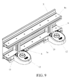
- Figure 9 shows one way of fixing a sidewall construction of the present invention onto a casting bed by means of a magnet unit 12 known from publication EP-A-1 075 917 .
- the sidewall construction according to Figure 9 comprises two horizontal profiles 1a and 1b, two vertical profiles 6 and a mold surface plate 3. At least one magnet (not shown in Figure 9 ) is located both in the lower 1a and the upper horizontal profile 1b.
- the sidewall construction is fixed to the casting bed by means of two magnet units 12.
- the magnet units 12 are fixed to the support construction of the sidewall construction by means of connection pieces 13.
- the sidewall construction of the present invention for a casting mold provides a sidewall construction having light weight and a simple construction for use in casting of concrete elements, said sidewall construction being easily cleanable and removable from the casting bed.
- the sidewall construction according to the invention provides a simple solution for varying the sidewall construction of the casting mold in a required way, when casting small production runs.
- Mold surface plates with different heights can be fixed to one and the same support construction of the present invention.
- fixing of mold surface plates to the support construction is significantly quicker than fixing the "sides" made of plywood with screws to a profile.
- the sidewall construction according to the invention also enables easy cleaning and storage of the constructions as ready stock items.
Landscapes
- Engineering & Computer Science (AREA)
- Manufacturing & Machinery (AREA)
- Chemical & Material Sciences (AREA)
- Ceramic Engineering (AREA)
- Mechanical Engineering (AREA)
- Forms Removed On Construction Sites Or Auxiliary Members Thereof (AREA)
- Non-Portable Lighting Devices Or Systems Thereof (AREA)
- Fencing (AREA)
Priority Applications (1)
| Application Number | Priority Date | Filing Date | Title |
|---|---|---|---|
| PL09397512T PL2113353T3 (pl) | 2008-04-29 | 2009-04-16 | Konstrukcja ścianki bocznej formy odlewniczej |
Applications Claiming Priority (1)
| Application Number | Priority Date | Filing Date | Title |
|---|---|---|---|
| FI20085388A FI125405B (fi) | 2008-04-29 | 2008-04-29 | Valumuotin laitarakenne |
Publications (3)
| Publication Number | Publication Date |
|---|---|
| EP2113353A2 true EP2113353A2 (fr) | 2009-11-04 |
| EP2113353A3 EP2113353A3 (fr) | 2011-06-22 |
| EP2113353B1 EP2113353B1 (fr) | 2012-11-21 |
Family
ID=39386011
Family Applications (1)
| Application Number | Title | Priority Date | Filing Date |
|---|---|---|---|
| EP09397512A Not-in-force EP2113353B1 (fr) | 2008-04-29 | 2009-04-16 | Construction de la paroi latérale d'un moule de coulée |
Country Status (9)
| Country | Link |
|---|---|
| US (1) | US8104737B2 (fr) |
| EP (1) | EP2113353B1 (fr) |
| AU (1) | AU2009201365B2 (fr) |
| DK (1) | DK2113353T3 (fr) |
| ES (1) | ES2399577T3 (fr) |
| FI (1) | FI125405B (fr) |
| HR (1) | HRP20130136T1 (fr) |
| PL (1) | PL2113353T3 (fr) |
| PT (1) | PT2113353E (fr) |
Cited By (1)
| Publication number | Priority date | Publication date | Assignee | Title |
|---|---|---|---|---|
| CN112092181A (zh) * | 2020-09-10 | 2020-12-18 | 连云港市成盛混凝土构件有限责任公司 | 一种装配式预制方涵成型装置及其制作工艺 |
Families Citing this family (4)
| Publication number | Priority date | Publication date | Assignee | Title |
|---|---|---|---|---|
| FI20105685L (fi) * | 2010-06-15 | 2011-12-16 | Elematic Group Oy | Valumuotin laitayksikkö sekä laitayksikön irrotusyksikkö |
| CN103406899B (zh) * | 2013-08-19 | 2016-03-16 | 长沙远大住宅工业集团有限公司 | 自动装模机械手 |
| US10947746B2 (en) * | 2018-09-06 | 2021-03-16 | MW Panel Tech, LLC | Configurable steel form system for fabricating precast panels |
| AU2025217312B1 (en) * | 2024-01-29 | 2026-01-08 | Shanxi Honghou Prefabricated Building Technology Development Group Co., Ltd | A production process for wall/floor panels for prefabricated buildings |
Citations (2)
| Publication number | Priority date | Publication date | Assignee | Title |
|---|---|---|---|---|
| EP1075917A2 (fr) | 1999-08-09 | 2001-02-14 | Addtek Research & Development Oy Ab | Dispositif de paroi latérale enlevable dans un moule pour le béton |
| EP1900489A2 (fr) | 2006-09-13 | 2008-03-19 | Elematic Oy Ab | Construction de la paroi latérale d'un moule |
Family Cites Families (26)
| Publication number | Priority date | Publication date | Assignee | Title |
|---|---|---|---|---|
| FR1344377A (fr) | 1962-10-15 | 1963-11-29 | Coignet Construct Edmond | Dispositif de moulage pour toutes matières, béton, béton armé, produits plastiques, céramiques et autres |
| US3530540A (en) | 1968-03-01 | 1970-09-29 | Ralph C Mueller | Molding device |
| US3730657A (en) | 1969-11-25 | 1973-05-01 | Nat Res Dev | Mold assembly for pressing concrete |
| GB1319082A (en) | 1970-06-08 | 1973-05-31 | Nat Res Dev | Concrete pressing processes and apparatus |
| DE3612742A1 (de) * | 1986-04-16 | 1987-11-05 | Maier Josef | Schalung mit zusammenfuegbaren schaltafeln |
| FI88472C (fi) * | 1990-06-18 | 1993-05-25 | Partek Concrete Oy Ab | Gjutform |
| DE4128293A1 (de) | 1991-08-27 | 1993-03-04 | Heinz Von Doellen | Verwahrungselement zur aufnahme von in betonbauteile teilweise einzubetonierende verbindungsstaehle |
| FI3486U1 (fi) * | 1998-03-27 | 1998-07-23 | Addtek Res & Dev Oy Ab | Valumuotin irrotettava laitajärjestelmä |
| FI3487U1 (fi) * | 1998-03-27 | 1998-07-23 | Addtek Res & Dev Oy Ab | Valumuotin irrotettava laitajärjestelmä |
| JP2000135709A (ja) | 1998-10-30 | 2000-05-16 | National House Industrial Co Ltd | 型 枠 |
| DE19961062A1 (de) * | 1999-12-17 | 2001-06-28 | Betoratio Gmbh | Schalungssystem |
| DE10130855B4 (de) | 2001-01-23 | 2005-07-14 | Georg Weidner | Längenveränderbare, insbesondere teleskopierbare Fixiervorrichtung für Schalungszwecke |
| FI4973U1 (fi) * | 2001-02-16 | 2001-06-27 | Addtek Res & Dev Oy Ab | Magneettiyksikkö valumuotin laitaa varten |
| US6540201B1 (en) * | 2001-02-26 | 2003-04-01 | White Cap Industries Incorporated | Tilt-up concrete panel forming system |
| US20050116131A1 (en) * | 2001-04-02 | 2005-06-02 | Michael Samuel | Support device |
| JP2003048207A (ja) * | 2001-08-07 | 2003-02-18 | Kiuchi Construction Co Ltd | コンクリート成形用型枠の固定装置 |
| DE10159902C2 (de) | 2001-12-06 | 2003-12-18 | Bt Baubedarf Magdeburg Gmbh | Positionierhilfe |
| FI5309U1 (fi) * | 2002-02-04 | 2002-04-04 | Addtek Res & Dev Oy Ab | Valumuotin laitojen kiinnitysjärjestely |
| JP3733390B2 (ja) * | 2002-04-01 | 2006-01-11 | 日本カイザー株式会社 | 型枠固定用治具。 |
| EP1547741A1 (fr) | 2002-10-02 | 2005-06-29 | Molcer, S.A. | Cadre de moule pour le pressage de carreaux, comportant un systeme de fixation magnetique des matrices |
| DE202005003979U1 (de) * | 2005-03-11 | 2006-07-20 | B.T. Innovation Gmbh | Schalungssystem |
| US7377341B2 (en) * | 2005-05-26 | 2008-05-27 | Smith International, Inc. | Thermally stable ultra-hard material compact construction |
| FI20050583L (fi) * | 2005-06-01 | 2006-12-02 | Elematic Oy Ab | Laitajärjestelmä valumuottiin |
| WO2007043897A2 (fr) | 2005-10-12 | 2007-04-19 | Itw New Zealand Limited | Ameliorations apportees a la construction de murs ou de panneaux |
| FI125406B (fi) * | 2006-01-20 | 2015-09-30 | Elematic Oyj | Muottijärjestelmä ja magneettiyksikkö |
| US20080023621A1 (en) | 2006-07-31 | 2008-01-31 | Wagner Eric W | Magnetic Concrete Construction Keyway System |
-
2008
- 2008-04-29 FI FI20085388A patent/FI125405B/fi not_active IP Right Cessation
-
2009
- 2009-04-07 AU AU2009201365A patent/AU2009201365B2/en not_active Ceased
- 2009-04-10 US US12/421,909 patent/US8104737B2/en not_active Expired - Fee Related
- 2009-04-16 ES ES09397512T patent/ES2399577T3/es active Active
- 2009-04-16 PL PL09397512T patent/PL2113353T3/pl unknown
- 2009-04-16 PT PT93975126T patent/PT2113353E/pt unknown
- 2009-04-16 EP EP09397512A patent/EP2113353B1/fr not_active Not-in-force
- 2009-04-16 DK DK09397512.6T patent/DK2113353T3/da active
-
2013
- 2013-02-19 HR HRP20130136AT patent/HRP20130136T1/hr unknown
Patent Citations (2)
| Publication number | Priority date | Publication date | Assignee | Title |
|---|---|---|---|---|
| EP1075917A2 (fr) | 1999-08-09 | 2001-02-14 | Addtek Research & Development Oy Ab | Dispositif de paroi latérale enlevable dans un moule pour le béton |
| EP1900489A2 (fr) | 2006-09-13 | 2008-03-19 | Elematic Oy Ab | Construction de la paroi latérale d'un moule |
Cited By (1)
| Publication number | Priority date | Publication date | Assignee | Title |
|---|---|---|---|---|
| CN112092181A (zh) * | 2020-09-10 | 2020-12-18 | 连云港市成盛混凝土构件有限责任公司 | 一种装配式预制方涵成型装置及其制作工艺 |
Also Published As
| Publication number | Publication date |
|---|---|
| AU2009201365A1 (en) | 2009-11-12 |
| ES2399577T3 (es) | 2013-04-02 |
| FI125405B (fi) | 2015-09-30 |
| DK2113353T3 (da) | 2013-03-04 |
| FI20085388A0 (fi) | 2008-04-29 |
| US8104737B2 (en) | 2012-01-31 |
| US20090266968A1 (en) | 2009-10-29 |
| PT2113353E (pt) | 2013-01-31 |
| AU2009201365B2 (en) | 2010-07-29 |
| EP2113353B1 (fr) | 2012-11-21 |
| PL2113353T3 (pl) | 2013-04-30 |
| EP2113353A3 (fr) | 2011-06-22 |
| HRP20130136T1 (hr) | 2013-03-31 |
| FI20085388L (fi) | 2009-10-30 |
Similar Documents
| Publication | Publication Date | Title |
|---|---|---|
| AU2007214294B2 (en) | Sidewall construction of a casting mold | |
| US8104737B2 (en) | Sidewall construction of a casting mold | |
| CN107529881B (zh) | 用于桌的桌架 | |
| US6047871A (en) | Brick cutting apparatus | |
| WO2002035965A3 (fr) | Support et etagere correspondante | |
| CN201137810Y (zh) | 新型铝合金型材 | |
| EP1724540A3 (fr) | Deviseur mobile pour un tiroir refrigéré | |
| CN207482488U (zh) | 一种用于成型木板的运输箱 | |
| EP1705126A3 (fr) | Dispositif de stockage et transport | |
| US6742759B2 (en) | Magnet unit for concrete moulds | |
| AU2007200021B2 (en) | Side system for a casting mold and an attaching unit | |
| US6948198B1 (en) | Bed with unitary headboard and unitary frame | |
| NL192993C (nl) | Bekistingssysteem. | |
| CN116423237A (zh) | 一种电饭锅内胆修边整边装置 | |
| JP2008161402A (ja) | 収納装置 | |
| CN210407731U (zh) | 一种酒柜的滑动搁架 | |
| CN218657534U (zh) | 一种防止安装摇晃的镀锌扁钢 | |
| US5692283A (en) | Pneumatic press for forming furniture bodies | |
| JPS641258B2 (fr) | ||
| JP2741526B2 (ja) | コンクリート打設用型枠組立治具 | |
| CN224131789U (zh) | 一种预制叠合板存放装置 | |
| CN216682650U (zh) | 一种制备预制混凝土构件的模具结构 | |
| US6286439B1 (en) | Side support for a hanging storage unit | |
| JP2007261124A (ja) | コンクリート成型品用の型枠パネル及びこれを用いた型枠装置 | |
| KR200293661Y1 (ko) | 실험실용 테이블 상판의 성형틀 |
Legal Events
| Date | Code | Title | Description |
|---|---|---|---|
| PUAI | Public reference made under article 153(3) epc to a published international application that has entered the european phase |
Free format text: ORIGINAL CODE: 0009012 |
|
| AK | Designated contracting states |
Kind code of ref document: A2 Designated state(s): AT BE BG CH CY CZ DE DK EE ES FI FR GB GR HR HU IE IS IT LI LT LU LV MC MK MT NL NO PL PT RO SE SI SK TR |
|
| PUAL | Search report despatched |
Free format text: ORIGINAL CODE: 0009013 |
|
| AK | Designated contracting states |
Kind code of ref document: A3 Designated state(s): AT BE BG CH CY CZ DE DK EE ES FI FR GB GR HR HU IE IS IT LI LT LU LV MC MK MT NL NO PL PT RO SE SI SK TR |
|
| 17P | Request for examination filed |
Effective date: 20111219 |
|
| GRAP | Despatch of communication of intention to grant a patent |
Free format text: ORIGINAL CODE: EPIDOSNIGR1 |
|
| RAP1 | Party data changed (applicant data changed or rights of an application transferred) |
Owner name: ELEMATIC OY AB |
|
| GRAS | Grant fee paid |
Free format text: ORIGINAL CODE: EPIDOSNIGR3 |
|
| GRAA | (expected) grant |
Free format text: ORIGINAL CODE: 0009210 |
|
| AK | Designated contracting states |
Kind code of ref document: B1 Designated state(s): AT BE BG CH CY CZ DE DK EE ES FI FR GB GR HR HU IE IS IT LI LT LU LV MC MK MT NL NO PL PT RO SE SI SK TR |
|
| REG | Reference to a national code |
Ref country code: GB Ref legal event code: FG4D |
|
| REG | Reference to a national code |
Ref country code: CH Ref legal event code: EP |
|
| REG | Reference to a national code |
Ref country code: AT Ref legal event code: REF Ref document number: 584808 Country of ref document: AT Kind code of ref document: T Effective date: 20121215 |
|
| REG | Reference to a national code |
Ref country code: IE Ref legal event code: FG4D |
|
| REG | Reference to a national code |
Ref country code: DE Ref legal event code: R096 Ref document number: 602009011341 Country of ref document: DE Effective date: 20130117 |
|
| REG | Reference to a national code |
Ref country code: PT Ref legal event code: SC4A Free format text: AVAILABILITY OF NATIONAL TRANSLATION Effective date: 20130124 Ref country code: CH Ref legal event code: NV Representative=s name: HEPP WENGER RYFFEL AG, CH |
|
| REG | Reference to a national code |
Ref country code: CH Ref legal event code: NV Representative=s name: HEPP WENGER RYFFEL AG, CH |
|
| REG | Reference to a national code |
Ref country code: RO Ref legal event code: EPE Ref country code: HR Ref legal event code: TUEP Ref document number: P20130136 Country of ref document: HR |
|
| REG | Reference to a national code |
Ref country code: SE Ref legal event code: TRGR |
|
| REG | Reference to a national code |
Ref country code: DK Ref legal event code: T3 |
|
| REG | Reference to a national code |
Ref country code: NL Ref legal event code: T3 |
|
| REG | Reference to a national code |
Ref country code: HR Ref legal event code: T1PR Ref document number: P20130136 Country of ref document: HR |
|
| REG | Reference to a national code |
Ref country code: ES Ref legal event code: FG2A Ref document number: 2399577 Country of ref document: ES Kind code of ref document: T3 Effective date: 20130402 |
|
| REG | Reference to a national code |
Ref country code: NO Ref legal event code: T2 Effective date: 20121121 |
|
| REG | Reference to a national code |
Ref country code: EE Ref legal event code: FG4A Ref document number: E007572 Country of ref document: EE Effective date: 20130220 |
|
| REG | Reference to a national code |
Ref country code: LT Ref legal event code: MG4D |
|
| PG25 | Lapsed in a contracting state [announced via postgrant information from national office to epo] |
Ref country code: LT Free format text: LAPSE BECAUSE OF FAILURE TO SUBMIT A TRANSLATION OF THE DESCRIPTION OR TO PAY THE FEE WITHIN THE PRESCRIBED TIME-LIMIT Effective date: 20121121 Ref country code: FI Free format text: LAPSE BECAUSE OF FAILURE TO SUBMIT A TRANSLATION OF THE DESCRIPTION OR TO PAY THE FEE WITHIN THE PRESCRIBED TIME-LIMIT Effective date: 20121121 |
|
| REG | Reference to a national code |
Ref country code: PL Ref legal event code: T3 |
|
| REG | Reference to a national code |
Ref country code: GR Ref legal event code: EP Ref document number: 20130400381 Country of ref document: GR Effective date: 20130327 |
|
| REG | Reference to a national code |
Ref country code: SK Ref legal event code: T3 Ref document number: E 13449 Country of ref document: SK |
|
| PG25 | Lapsed in a contracting state [announced via postgrant information from national office to epo] |
Ref country code: SI Free format text: LAPSE BECAUSE OF FAILURE TO SUBMIT A TRANSLATION OF THE DESCRIPTION OR TO PAY THE FEE WITHIN THE PRESCRIBED TIME-LIMIT Effective date: 20121121 Ref country code: LV Free format text: LAPSE BECAUSE OF FAILURE TO SUBMIT A TRANSLATION OF THE DESCRIPTION OR TO PAY THE FEE WITHIN THE PRESCRIBED TIME-LIMIT Effective date: 20121121 |
|
| PLBE | No opposition filed within time limit |
Free format text: ORIGINAL CODE: 0009261 |
|
| STAA | Information on the status of an ep patent application or granted ep patent |
Free format text: STATUS: NO OPPOSITION FILED WITHIN TIME LIMIT |
|
| REG | Reference to a national code |
Ref country code: HU Ref legal event code: AG4A Ref document number: E016570 Country of ref document: HU |
|
| 26N | No opposition filed |
Effective date: 20130822 |
|
| PG25 | Lapsed in a contracting state [announced via postgrant information from national office to epo] |
Ref country code: MC Free format text: LAPSE BECAUSE OF FAILURE TO SUBMIT A TRANSLATION OF THE DESCRIPTION OR TO PAY THE FEE WITHIN THE PRESCRIBED TIME-LIMIT Effective date: 20121121 |
|
| REG | Reference to a national code |
Ref country code: DE Ref legal event code: R097 Ref document number: 602009011341 Country of ref document: DE Effective date: 20130822 |
|
| PG25 | Lapsed in a contracting state [announced via postgrant information from national office to epo] |
Ref country code: MT Free format text: LAPSE BECAUSE OF FAILURE TO SUBMIT A TRANSLATION OF THE DESCRIPTION OR TO PAY THE FEE WITHIN THE PRESCRIBED TIME-LIMIT Effective date: 20121121 |
|
| PG25 | Lapsed in a contracting state [announced via postgrant information from national office to epo] |
Ref country code: TR Free format text: LAPSE BECAUSE OF FAILURE TO SUBMIT A TRANSLATION OF THE DESCRIPTION OR TO PAY THE FEE WITHIN THE PRESCRIBED TIME-LIMIT Effective date: 20121121 Ref country code: CY Free format text: LAPSE BECAUSE OF FAILURE TO SUBMIT A TRANSLATION OF THE DESCRIPTION OR TO PAY THE FEE WITHIN THE PRESCRIBED TIME-LIMIT Effective date: 20121121 |
|
| PG25 | Lapsed in a contracting state [announced via postgrant information from national office to epo] |
Ref country code: MK Free format text: LAPSE BECAUSE OF FAILURE TO SUBMIT A TRANSLATION OF THE DESCRIPTION OR TO PAY THE FEE WITHIN THE PRESCRIBED TIME-LIMIT Effective date: 20121121 Ref country code: LU Free format text: LAPSE BECAUSE OF NON-PAYMENT OF DUE FEES Effective date: 20130416 |
|
| REG | Reference to a national code |
Ref country code: FR Ref legal event code: PLFP Year of fee payment: 8 |
|
| PG25 | Lapsed in a contracting state [announced via postgrant information from national office to epo] |
Ref country code: IS Free format text: LAPSE BECAUSE OF FAILURE TO SUBMIT A TRANSLATION OF THE DESCRIPTION OR TO PAY THE FEE WITHIN THE PRESCRIBED TIME-LIMIT Effective date: 20121121 |
|
| REG | Reference to a national code |
Ref country code: HR Ref legal event code: ODRP Ref document number: P20130136 Country of ref document: HR Payment date: 20170403 Year of fee payment: 9 |
|
| REG | Reference to a national code |
Ref country code: FR Ref legal event code: PLFP Year of fee payment: 9 |
|
| PGFP | Annual fee paid to national office [announced via postgrant information from national office to epo] |
Ref country code: RO Payment date: 20170327 Year of fee payment: 9 |
|
| PGFP | Annual fee paid to national office [announced via postgrant information from national office to epo] |
Ref country code: CZ Payment date: 20170324 Year of fee payment: 9 Ref country code: PL Payment date: 20170324 Year of fee payment: 9 |
|
| PGFP | Annual fee paid to national office [announced via postgrant information from national office to epo] |
Ref country code: NL Payment date: 20170419 Year of fee payment: 9 |
|
| PGFP | Annual fee paid to national office [announced via postgrant information from national office to epo] |
Ref country code: SK Payment date: 20170411 Year of fee payment: 9 Ref country code: DK Payment date: 20170419 Year of fee payment: 9 Ref country code: GR Payment date: 20170425 Year of fee payment: 9 Ref country code: GB Payment date: 20170419 Year of fee payment: 9 Ref country code: DE Payment date: 20170419 Year of fee payment: 9 Ref country code: EE Payment date: 20170426 Year of fee payment: 9 Ref country code: IE Payment date: 20170421 Year of fee payment: 9 Ref country code: NO Payment date: 20170425 Year of fee payment: 9 Ref country code: CH Payment date: 20170419 Year of fee payment: 9 Ref country code: HR Payment date: 20170403 Year of fee payment: 9 Ref country code: FR Payment date: 20170419 Year of fee payment: 9 |
|
| PGFP | Annual fee paid to national office [announced via postgrant information from national office to epo] |
Ref country code: BE Payment date: 20170419 Year of fee payment: 9 Ref country code: AT Payment date: 20170420 Year of fee payment: 9 Ref country code: BG Payment date: 20170425 Year of fee payment: 9 Ref country code: SE Payment date: 20170419 Year of fee payment: 9 Ref country code: ES Payment date: 20170510 Year of fee payment: 9 Ref country code: IT Payment date: 20170420 Year of fee payment: 9 Ref country code: PT Payment date: 20170417 Year of fee payment: 9 |
|
| PGFP | Annual fee paid to national office [announced via postgrant information from national office to epo] |
Ref country code: HU Payment date: 20170419 Year of fee payment: 9 |
|
| REG | Reference to a national code |
Ref country code: HR Ref legal event code: PBON Ref document number: P20130136 Country of ref document: HR Effective date: 20180416 |
|
| REG | Reference to a national code |
Ref country code: DE Ref legal event code: R119 Ref document number: 602009011341 Country of ref document: DE |
|
| REG | Reference to a national code |
Ref country code: EE Ref legal event code: MM4A Ref document number: E007572 Country of ref document: EE Effective date: 20180430 |
|
| REG | Reference to a national code |
Ref country code: DK Ref legal event code: EBP Effective date: 20180430 Ref country code: NO Ref legal event code: MMEP |
|
| REG | Reference to a national code |
Ref country code: CH Ref legal event code: PL |
|
| REG | Reference to a national code |
Ref country code: SE Ref legal event code: EUG |
|
| REG | Reference to a national code |
Ref country code: NL Ref legal event code: MM Effective date: 20180501 |
|
| REG | Reference to a national code |
Ref country code: AT Ref legal event code: MM01 Ref document number: 584808 Country of ref document: AT Kind code of ref document: T Effective date: 20180416 |
|
| REG | Reference to a national code |
Ref country code: BE Ref legal event code: MM Effective date: 20180430 |
|
| GBPC | Gb: european patent ceased through non-payment of renewal fee |
Effective date: 20180416 |
|
| REG | Reference to a national code |
Ref country code: SK Ref legal event code: MM4A Ref document number: E 13449 Country of ref document: SK Effective date: 20180416 |
|
| REG | Reference to a national code |
Ref country code: IE Ref legal event code: MM4A |
|
| PG25 | Lapsed in a contracting state [announced via postgrant information from national office to epo] |
Ref country code: HU Free format text: LAPSE BECAUSE OF NON-PAYMENT OF DUE FEES Effective date: 20180417 Ref country code: DE Free format text: LAPSE BECAUSE OF NON-PAYMENT OF DUE FEES Effective date: 20181101 Ref country code: GR Free format text: LAPSE BECAUSE OF NON-PAYMENT OF DUE FEES Effective date: 20181106 Ref country code: NO Free format text: LAPSE BECAUSE OF NON-PAYMENT OF DUE FEES Effective date: 20180430 Ref country code: SE Free format text: LAPSE BECAUSE OF NON-PAYMENT OF DUE FEES Effective date: 20180417 Ref country code: NL Free format text: LAPSE BECAUSE OF NON-PAYMENT OF DUE FEES Effective date: 20180501 Ref country code: AT Free format text: LAPSE BECAUSE OF NON-PAYMENT OF DUE FEES Effective date: 20180416 Ref country code: CZ Free format text: LAPSE BECAUSE OF NON-PAYMENT OF DUE FEES Effective date: 20180416 Ref country code: EE Free format text: LAPSE BECAUSE OF NON-PAYMENT OF DUE FEES Effective date: 20180430 Ref country code: RO Free format text: LAPSE BECAUSE OF NON-PAYMENT OF DUE FEES Effective date: 20180416 Ref country code: PT Free format text: LAPSE BECAUSE OF NON-PAYMENT OF DUE FEES Effective date: 20181016 Ref country code: SK Free format text: LAPSE BECAUSE OF NON-PAYMENT OF DUE FEES Effective date: 20180416 |
|
| PG25 | Lapsed in a contracting state [announced via postgrant information from national office to epo] |
Ref country code: BE Free format text: LAPSE BECAUSE OF NON-PAYMENT OF DUE FEES Effective date: 20180430 Ref country code: HR Free format text: LAPSE BECAUSE OF NON-PAYMENT OF DUE FEES Effective date: 20180416 Ref country code: CH Free format text: LAPSE BECAUSE OF NON-PAYMENT OF DUE FEES Effective date: 20180430 Ref country code: LI Free format text: LAPSE BECAUSE OF NON-PAYMENT OF DUE FEES Effective date: 20180430 Ref country code: GB Free format text: LAPSE BECAUSE OF NON-PAYMENT OF DUE FEES Effective date: 20180416 |
|
| PG25 | Lapsed in a contracting state [announced via postgrant information from national office to epo] |
Ref country code: FR Free format text: LAPSE BECAUSE OF NON-PAYMENT OF DUE FEES Effective date: 20180430 Ref country code: IT Free format text: LAPSE BECAUSE OF NON-PAYMENT OF DUE FEES Effective date: 20180416 Ref country code: IE Free format text: LAPSE BECAUSE OF NON-PAYMENT OF DUE FEES Effective date: 20180416 |
|
| PG25 | Lapsed in a contracting state [announced via postgrant information from national office to epo] |
Ref country code: DK Free format text: LAPSE BECAUSE OF NON-PAYMENT OF DUE FEES Effective date: 20180430 |
|
| PG25 | Lapsed in a contracting state [announced via postgrant information from national office to epo] |
Ref country code: BG Free format text: LAPSE BECAUSE OF NON-PAYMENT OF DUE FEES Effective date: 20190430 |
|
| REG | Reference to a national code |
Ref country code: ES Ref legal event code: FD2A Effective date: 20190912 |
|
| PG25 | Lapsed in a contracting state [announced via postgrant information from national office to epo] |
Ref country code: ES Free format text: LAPSE BECAUSE OF NON-PAYMENT OF DUE FEES Effective date: 20180417 |
|
| PG25 | Lapsed in a contracting state [announced via postgrant information from national office to epo] |
Ref country code: PL Free format text: LAPSE BECAUSE OF NON-PAYMENT OF DUE FEES Effective date: 20180416 |