EP1075917A2 - Dispositif de paroi latérale enlevable dans un moule pour le béton - Google Patents
Dispositif de paroi latérale enlevable dans un moule pour le béton Download PDFInfo
- Publication number
- EP1075917A2 EP1075917A2 EP00660135A EP00660135A EP1075917A2 EP 1075917 A2 EP1075917 A2 EP 1075917A2 EP 00660135 A EP00660135 A EP 00660135A EP 00660135 A EP00660135 A EP 00660135A EP 1075917 A2 EP1075917 A2 EP 1075917A2
- Authority
- EP
- European Patent Office
- Prior art keywords
- mould side
- mould
- magnet
- magnet unit
- casting bed
- Prior art date
- Legal status (The legal status is an assumption and is not a legal conclusion. Google has not performed a legal analysis and makes no representation as to the accuracy of the status listed.)
- Granted
Links
Images


Classifications
-
- B—PERFORMING OPERATIONS; TRANSPORTING
- B28—WORKING CEMENT, CLAY, OR STONE
- B28B—SHAPING CLAY OR OTHER CERAMIC COMPOSITIONS; SHAPING SLAG; SHAPING MIXTURES CONTAINING CEMENTITIOUS MATERIAL, e.g. PLASTER
- B28B7/00—Moulds; Cores; Mandrels
- B28B7/0002—Auxiliary parts or elements of the mould
- B28B7/0014—Fastening means for mould parts, e.g. for attaching mould walls on mould tables; Mould clamps
- B28B7/0017—Fastening means for mould parts, e.g. for attaching mould walls on mould tables; Mould clamps for attaching mould walls on mould tables
-
- B—PERFORMING OPERATIONS; TRANSPORTING
- B28—WORKING CEMENT, CLAY, OR STONE
- B28B—SHAPING CLAY OR OTHER CERAMIC COMPOSITIONS; SHAPING SLAG; SHAPING MIXTURES CONTAINING CEMENTITIOUS MATERIAL, e.g. PLASTER
- B28B7/00—Moulds; Cores; Mandrels
- B28B7/0002—Auxiliary parts or elements of the mould
- B28B7/0014—Fastening means for mould parts, e.g. for attaching mould walls on mould tables; Mould clamps
- B28B7/002—Fastening means for mould parts, e.g. for attaching mould walls on mould tables; Mould clamps using magnets
-
- Y—GENERAL TAGGING OF NEW TECHNOLOGICAL DEVELOPMENTS; GENERAL TAGGING OF CROSS-SECTIONAL TECHNOLOGIES SPANNING OVER SEVERAL SECTIONS OF THE IPC; TECHNICAL SUBJECTS COVERED BY FORMER USPC CROSS-REFERENCE ART COLLECTIONS [XRACs] AND DIGESTS
- Y10—TECHNICAL SUBJECTS COVERED BY FORMER USPC
- Y10S—TECHNICAL SUBJECTS COVERED BY FORMER USPC CROSS-REFERENCE ART COLLECTIONS [XRACs] AND DIGESTS
- Y10S425/00—Plastic article or earthenware shaping or treating: apparatus
- Y10S425/033—Magnet
Definitions
- This invention relates to a concrete mould side system comprising a side part that can be removably attached to a casting bed by means of one or more magnets.
- Removable mould sides that are provided with different kinds of fastener solutions and designed for a concrete mould for casting elements from concrete have been disclosed in the prior art. These sides can be placed in desired positions on the casting bed depending on the size and shape of the object to be cast.
- the horizontal mould is usually a table mould, i.e. a tiltable mould with sides.
- a concrete dispenser moves above the table and allows a defined amount of mass to flow into the mould.
- the table is tipped about a tilting axis provided on one side, into an almost upright position. The mould side that ends up in the upper position is removed, and the element is lifted away from the table using rings provided on its sides.
- the position of the upper side has to be adjustable according to the size of the element to be cast.
- Removable mould sides can be used for this purpose.
- removable and adjustable mould side units enable door or window openings to be made at desired locations in the element.
- magnets for fastening removable mould sides is well known in the art. They are very suitable for fastening a mould side as they attach themselves to the flat steel surface of the casting bed. In order to secure a firm attachment of the mould side, strong magnets generating an attractive force of e.g. 15 kN must be used.
- a magnetic mould side fastening system wherein the frame of the magnet-carrying unit comprises a tilting axis about which the magnet unit can be tilted into a lower position, in which the magnet is contact with the casting bed, and into an upper position in which the magnet is not in contact with the casting bed.
- the mould side unit comprises a support on which the tilting axle of the magnet unit can be thus supported, that the unit is movable between a lower and an upper position, and the support has a gripping surface to which the upper surface of the magnet can be attached by means of attraction force when the magnet is tilted into its upper position about its tilting axle.
- the magnet is detached from the bed by means of a double acting lever.
- This invention concerns a concrete mould side system according to claim 1.
- the invention provides a system for fastening a magnet to a mould side, which system is simpler and more versatile than those previously known.
- a separate magnet unit comprises a tiltable permanent magnet.
- the magnet unit is fastened to a counterpart provided on the mould side by means of an oblique projecting member provided on its front face, engaging a corresponding groove in the counterpart.
- the front face of the magnet unit is designed to set at an angle of exactly 90° to the casting bed when the magnet unit is fastened to the mould side, the front face of the magnet unit biting into the back face of the mould side due to the characteristic wedging groove action, and keeping the side upright all the time.
- the magnet unit In its fastened position, the magnet unit is always supported by the bottom surface of its rear end and by the side profile, since the bottom surface of the front end of the magnet is not in contact with the casting bed when the magnet is fastened to the mould side.
- the projecting member of the magnet unit can be directly complementary in shape, or it can be an oblique pin or tongue penetrating into an oblique hole, a saw-cut or the like forming the counter-groove.
- the system according to the invention affects the mould side by the most direct vertical pressing force possible without using long levers. The internal forces of the system render the contact surface between the side and the magnet unit absolutely steady.
- the joint between the mould side and the casting bed is sealed at its front edge, and the mould side is prevented from falling backwards.
- the fastening is an easy and quick process, and the magnet can be coupled to any location on the mould side. This way of fastening makes it possible to place the mould side in the correct position without restrictions, and to release the fastening magnet without moving the mould side.
- the system according to the invention may comprise a ready-to-use side profile having a running counter-groove for the magnet unit's gripping member on its back face.
- the profile may be sold by the meter and can be cut into desired lengths. It can be made from steel, or for instance from extruded light alloy.
- the profile may form a mould side as such, or it may be provided with a front face of plywood, in one piece or divided into sections. Since the mould side comprises the guiding counter-groove, different kinds of openings, such as window and door openings, can easily be created therefrom by means of braces. Instead of having a continuous profile, the mould side can be provided with local, shorter oblique counter-grooves.
- An important property of the magnet unit according to the invention is that it can be located at the joints between mould side units, where it not only attaches the side units to the bed but also joins them together. Using suitable fastening fittings, angle joints can also be formed. In addition to the groove joint, the magnet unit can be fastened to the mould side unit with screws. Both the magnet unit's front face and the upper surface perpendicular thereto are preferably provided with threaded holes. These fastening provisions make any local applications possible.
- the mould side is made from high tensile steel. It can also be made from extruded aluminum, light metal, plastic or the like. The construction enables light and durable designs, and designs which as a whole are as narrow as possible.
- the shape of the side enables the use of robotics in transport and storage of the mould sides.
- Figure 1 shows the magnet unit according to the invention fastened to a mould side and with the magnet attached to the casting bed.
- Figure 2 shows the same parts with the magnet in a released position.
- narrow claws arranged in vertical steel bars of the mould side are used instead of a continuous counter-groove profile.
- the lever system for attaching the magnet to the casting bed and for detaching it therefrom is disclosed in European patent application no. 996600500.8
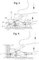
- the magnet unit 20 has a frame 1 and a tiltable part 3 comprising a permanent magnet 2.
- the permanent magnet is fastened to the tiltable part by an adjustable screw 5, which screw is secured within a protecting bushing 4 and enables vertical adjustment of the magnet in order to ensure good alignment and a tight fit at all locations relative to the mould side.
- the magnet is shown in both attached and detached positions.
- the tiltable part is shown attached to the casting bed and detached therefrom by continuous and broken lines, respectively.
- the magnet unit is fastened to the mould side by pushing the projecting member 7 of the oblique groove 6 of the front face 22 into a counter-groove provided in the mould side.
- the middlemost, upper branch 15 is pushed into a cavity provided in the tiltable part, below the upper release surface 17.
- the magnet can be detached from the bed by means of the outer branches, by pressing the bar of the release lever downwards. Only a small leverage is required to accomplish this. Subsequently, the bar of the release lever is lifted, as a result of which the middlemost branch of the lever rests firmly in the cavity and the magnet tilts upwards and engages body 1.
- the weight of the magnet unit is moderate, and it is easy to handle and adjust.
- the entire attraction force of the magnet which may be in the order of 14 kN, is optimized to keep the mould side against the casting bed.
- the front face and upper surface of frame 1 may comprise threaded holes 18 and 19 for screw joints.
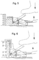
- Figure 4 is a cross-sectional side view of the magnet unit according to the invention, fastened to mould side 9.
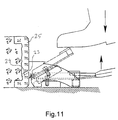
- Figures 5 to 8 show other embodiments of the mould side according to the invention, wherein the structure and material of the mould vary, as will be understood by those skilled in the art. However, all the embodiments shown comprise a magnet unit counter-groove according to the present invention.
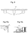
- Figure 9 shows how the system according to the invention can be applied at a straight mould side extension.
- the magnet unit 20 is thus located, that the wedging members on the front face of the magnet unit engage the mould side counter-grooves of the side units on both sides of joint 21.
- Figures 10a and 10b show how mould side units positioned at an angle respective to each other can be joined together by means of a corner profile adapter unit, which in turn is fastened to the casting bed using a magnet unit according to the present invention.
- the projecting part of the magnet unit consists of at least one oblique pin 23 that penetrates into an oblique hole (or holes, respectively) 24 provided in the mould side, generating a downward force for the mould, as a result of which the magnet's wedging pair of forces acts to straighten the front face of the mould side into an exactly perpendicular position.
- This embodiment is particularly useful for ready-to-use element mould sides made from line-grained, fiber-reinforced concrete mix, so-called fiber sides 25, or e.g. for plain mould sides made from plywood.
- the required oblique holes can be drilled in the mould side with the aid of a guide tool at the cutting stage, or on the casting bed following mould assembly. Tongue-shaped protrusions and saw-cuts can also be used.
Landscapes
- Engineering & Computer Science (AREA)
- Manufacturing & Machinery (AREA)
- Chemical & Material Sciences (AREA)
- Ceramic Engineering (AREA)
- Mechanical Engineering (AREA)
- Moulds, Cores, Or Mandrels (AREA)
- Forms Removed On Construction Sites Or Auxiliary Members Thereof (AREA)
- On-Site Construction Work That Accompanies The Preparation And Application Of Concrete (AREA)
- Moulds For Moulding Plastics Or The Like (AREA)
- Casting Devices For Molds (AREA)
- Molds, Cores, And Manufacturing Methods Thereof (AREA)
- Sewing Machines And Sewing (AREA)
- Battery Mounting, Suspending (AREA)
- Paper (AREA)
Priority Applications (1)
| Application Number | Priority Date | Filing Date | Title |
|---|---|---|---|
| DK00660135T DK1075917T3 (da) | 1999-08-09 | 2000-08-09 | Aftageligt sidesystem til en betonstöbeform |
Applications Claiming Priority (2)
| Application Number | Priority Date | Filing Date | Title |
|---|---|---|---|
| FI990339U | 1999-08-09 | ||
| FI990339U FI4258U1 (fi) | 1999-08-09 | 1999-08-09 | Valumuotin irrotettava laitajärjestelmä |
Publications (3)
| Publication Number | Publication Date |
|---|---|
| EP1075917A2 true EP1075917A2 (fr) | 2001-02-14 |
| EP1075917A3 EP1075917A3 (fr) | 2002-12-11 |
| EP1075917B1 EP1075917B1 (fr) | 2004-09-29 |
Family
ID=8553833
Family Applications (1)
| Application Number | Title | Priority Date | Filing Date |
|---|---|---|---|
| EP00660135A Expired - Lifetime EP1075917B1 (fr) | 1999-08-09 | 2000-08-09 | Dispositif de paroi latérale enlevable dans un moule pour le béton |
Country Status (7)
| Country | Link |
|---|---|
| US (1) | US6547209B1 (fr) |
| EP (1) | EP1075917B1 (fr) |
| AT (1) | ATE277729T1 (fr) |
| DE (1) | DE60014284T2 (fr) |
| DK (1) | DK1075917T3 (fr) |
| ES (1) | ES2226756T3 (fr) |
| FI (1) | FI4258U1 (fr) |
Cited By (10)
| Publication number | Priority date | Publication date | Assignee | Title |
|---|---|---|---|---|
| EP1232842A3 (fr) * | 2001-02-16 | 2003-09-17 | Addtek Research & Development Oy Ab | Unité d'aimant pour les coffrages de béton |
| US6860462B2 (en) * | 2002-02-04 | 2005-03-01 | Consolis Technology Oy Ab | Clamping arrangement for casting mold sidewalls |
| EP1352723A3 (fr) * | 2002-04-08 | 2005-04-06 | Consolis Technology Oy Ab | Système de paroi latérale démontable pour moule de coulage |
| WO2006094547A1 (fr) * | 2005-03-11 | 2006-09-14 | B.T. Innovation Gmbh | Systeme de coffrage |
| WO2005058567A3 (fr) * | 2003-12-17 | 2009-03-19 | Georg Weidner | Unite de coffrage avec element de moulage ou de profilage pour materiaux de construction |
| EP2113353A2 (fr) | 2008-04-29 | 2009-11-04 | Elematic Group Oy | Construction de la paroi latérale d'un moule de coulée |
| EP1789233A4 (fr) * | 2004-08-24 | 2010-04-21 | Srb Construction Technologies | Agrafe magnétique |
| EP1900489A3 (fr) * | 2006-09-13 | 2010-10-06 | Elematic Oy Ab | Construction de la paroi latérale d'un moule |
| EP2641713A2 (fr) | 2012-03-22 | 2013-09-25 | Lujabetoni OY | Système de moule de coulage du béton |
| CN110584349A (zh) * | 2019-07-31 | 2019-12-20 | 黄杰 | 一种基于大数据防止外界因素干扰的智能家居系统 |
Families Citing this family (12)
| Publication number | Priority date | Publication date | Assignee | Title |
|---|---|---|---|---|
| US20050116131A1 (en) * | 2001-04-02 | 2005-06-02 | Michael Samuel | Support device |
| DE10159902C2 (de) * | 2001-12-06 | 2003-12-18 | Bt Baubedarf Magdeburg Gmbh | Positionierhilfe |
| DE20309970U1 (de) * | 2003-06-27 | 2004-11-04 | Bt Baubedarf Magdeburg Gmbh | Halteeinrichtung |
| DK1778932T3 (da) * | 2004-05-24 | 2010-11-08 | Srb Construction Technologies | Sideforskallingssystem til beton |
| NZ555301A (en) * | 2004-12-16 | 2011-01-28 | Srb Construction Technologies Pty Ltd | An adapter for a magnetic clamp |
| AU2005316202B2 (en) * | 2004-12-16 | 2010-04-22 | Itw Australia Pty Ltd | An adapter for a magnetic clamp |
| FI20050583L (fi) * | 2005-06-01 | 2006-12-02 | Elematic Oy Ab | Laitajärjestelmä valumuottiin |
| CA2697335C (fr) * | 2006-09-15 | 2015-11-10 | Srb Construction Technologies Pty Ltd. | Agrafeuse magnetique |
| CA2697317C (fr) * | 2006-09-18 | 2015-11-10 | Robert Sladojevic | Dispositif de serrage magnetique |
| FI20105685L (fi) * | 2010-06-15 | 2011-12-16 | Elematic Group Oy | Valumuotin laitayksikkö sekä laitayksikön irrotusyksikkö |
| DE202010010161U1 (de) | 2010-07-13 | 2010-10-14 | Laudan, Thomas | Schalungsträgersystem |
| US8876096B2 (en) * | 2012-07-05 | 2014-11-04 | The Boeing Company | Method and apparatus for forming an angled flange |
Family Cites Families (7)
| Publication number | Priority date | Publication date | Assignee | Title |
|---|---|---|---|---|
| US1431635A (en) * | 1920-06-01 | 1922-10-10 | Frank M Conroy | Mold for use in production of fenceposts |
| GB1301272A (fr) * | 1968-11-26 | 1972-12-29 | ||
| DE2907508A1 (de) | 1979-02-26 | 1980-09-04 | Magnetfab Bonn Gmbh | Flachhaft-dauermagnet zur fixierung von schalungsteilen |
| FR2552145B1 (fr) | 1983-09-15 | 1986-05-23 | Quille Entreprise | Dispositif de maintien d'un element de reservation ou d'arret de coulage sur un element de coffrage metallique |
| DE19528842A1 (de) * | 1995-08-04 | 1997-02-06 | Reymann Technik Gmbh | Schalungssystem für Betonfertigteile |
| FI3486U1 (fi) * | 1998-03-27 | 1998-07-23 | Addtek Res & Dev Oy Ab | Valumuotin irrotettava laitajärjestelmä |
| FI3487U1 (fi) * | 1998-03-27 | 1998-07-23 | Addtek Res & Dev Oy Ab | Valumuotin irrotettava laitajärjestelmä |
-
1999
- 1999-08-09 FI FI990339U patent/FI4258U1/fi active
-
2000
- 2000-08-04 US US09/633,097 patent/US6547209B1/en not_active Expired - Lifetime
- 2000-08-09 DK DK00660135T patent/DK1075917T3/da active
- 2000-08-09 ES ES00660135T patent/ES2226756T3/es not_active Expired - Lifetime
- 2000-08-09 AT AT00660135T patent/ATE277729T1/de active
- 2000-08-09 DE DE60014284T patent/DE60014284T2/de not_active Expired - Lifetime
- 2000-08-09 EP EP00660135A patent/EP1075917B1/fr not_active Expired - Lifetime
Cited By (14)
| Publication number | Priority date | Publication date | Assignee | Title |
|---|---|---|---|---|
| EP1232842A3 (fr) * | 2001-02-16 | 2003-09-17 | Addtek Research & Development Oy Ab | Unité d'aimant pour les coffrages de béton |
| US6742759B2 (en) * | 2001-02-16 | 2004-06-01 | Addtek Research & Development Oy Ab | Magnet unit for concrete moulds |
| US6860462B2 (en) * | 2002-02-04 | 2005-03-01 | Consolis Technology Oy Ab | Clamping arrangement for casting mold sidewalls |
| EP1352723A3 (fr) * | 2002-04-08 | 2005-04-06 | Consolis Technology Oy Ab | Système de paroi latérale démontable pour moule de coulage |
| WO2005058567A3 (fr) * | 2003-12-17 | 2009-03-19 | Georg Weidner | Unite de coffrage avec element de moulage ou de profilage pour materiaux de construction |
| EP1789233A4 (fr) * | 2004-08-24 | 2010-04-21 | Srb Construction Technologies | Agrafe magnétique |
| WO2006094547A1 (fr) * | 2005-03-11 | 2006-09-14 | B.T. Innovation Gmbh | Systeme de coffrage |
| US7887022B2 (en) | 2005-03-11 | 2011-02-15 | B.T. Innovation Gmbh | Formwork system |
| EP1900489A3 (fr) * | 2006-09-13 | 2010-10-06 | Elematic Oy Ab | Construction de la paroi latérale d'un moule |
| AU2009201365B2 (en) * | 2008-04-29 | 2010-07-29 | Elematic Group Oy | Sidewall construction of a casting mold |
| EP2113353A2 (fr) | 2008-04-29 | 2009-11-04 | Elematic Group Oy | Construction de la paroi latérale d'un moule de coulée |
| EP2641713A2 (fr) | 2012-03-22 | 2013-09-25 | Lujabetoni OY | Système de moule de coulage du béton |
| CN110584349A (zh) * | 2019-07-31 | 2019-12-20 | 黄杰 | 一种基于大数据防止外界因素干扰的智能家居系统 |
| CN110584349B (zh) * | 2019-07-31 | 2021-04-06 | 深圳市华壹装饰科技设计工程有限公司 | 一种基于大数据防止外界因素干扰的智能家居系统 |
Also Published As
| Publication number | Publication date |
|---|---|
| EP1075917A3 (fr) | 2002-12-11 |
| DE60014284D1 (de) | 2004-11-04 |
| ES2226756T3 (es) | 2005-04-01 |
| EP1075917B1 (fr) | 2004-09-29 |
| FI4258U1 (fi) | 1999-12-15 |
| US6547209B1 (en) | 2003-04-15 |
| DE60014284T2 (de) | 2005-02-03 |
| FIU990339U0 (fi) | 1999-08-09 |
| ATE277729T1 (de) | 2004-10-15 |
| DK1075917T3 (da) | 2004-11-29 |
Similar Documents
| Publication | Publication Date | Title |
|---|---|---|
| EP1075917B1 (fr) | Dispositif de paroi latérale enlevable dans un moule pour le béton | |
| AU2007214294B2 (en) | Sidewall construction of a casting mold | |
| EP0945238A2 (fr) | Dispositif de paroi latérale amovible pour moule | |
| EP0945237B1 (fr) | Dispositif de paroi latérale enlevable pour moule de coulage | |
| EP1810806A2 (fr) | Dispositif de paroi latérale pour moule de coulage et unité d'attache | |
| EP1232842B1 (fr) | Unité d'aimant pour les coffrages de béton | |
| JPS573535U (fr) | ||
| CA2162454A1 (fr) | Garniture de cercueil a verrouillage a glissiere pouvant etre enlevee de l'exterieur | |
| EP1149957A3 (fr) | Système de barres profilées | |
| US7055792B2 (en) | Clamp device for side wall beams | |
| US4244235A (en) | Apparatus for attaching a brake lever stay to a handle bar of a bicycle | |
| JPH0967886A (ja) | 立設部材の安定脚装置 | |
| JP2508892Y2 (ja) | サッシ施工治具 | |
| JP2890737B2 (ja) | 天板の高さ調整装置 | |
| JPH07255550A (ja) | カウンターの接合構造 | |
| GB2399531A (en) | Foot-operable clamp device | |
| JPH0735986Y2 (ja) | 外装材の取付け装置 | |
| JP2598086Y2 (ja) | 花輪用三脚 | |
| JPS6119710Y2 (fr) | ||
| JPH0797028A (ja) | コンベヤフレーム | |
| CA3241114A1 (fr) | Presse-plieuse modulaire ayant des composants et des accessoires ameliores | |
| KR960002467Y1 (ko) | 작업대 | |
| JP2003064866A (ja) | 布板の長さ調整構造 | |
| JP2593153Y2 (ja) | 取付金具 | |
| CA1256718A (fr) | Monture reglable |
Legal Events
| Date | Code | Title | Description |
|---|---|---|---|
| PUAI | Public reference made under article 153(3) epc to a published international application that has entered the european phase |
Free format text: ORIGINAL CODE: 0009012 |
|
| AK | Designated contracting states |
Kind code of ref document: A2 Designated state(s): AT BE CH CY DE DK ES FI FR GB GR IE IT LI LU MC NL PT SE |
|
| AX | Request for extension of the european patent |
Free format text: AL;LT;LV;MK;RO;SI |
|
| RAP1 | Party data changed (applicant data changed or rights of an application transferred) |
Owner name: ADDTEK RESEARCH & DEVELOPMENT OY AB |
|
| RIN1 | Information on inventor provided before grant (corrected) |
Inventor name: VAPPULA, KARI |
|
| PUAL | Search report despatched |
Free format text: ORIGINAL CODE: 0009013 |
|
| AK | Designated contracting states |
Kind code of ref document: A3 Designated state(s): AT BE CH CY DE DK ES FI FR GB GR IE IT LI LU MC NL PT SE |
|
| AX | Request for extension of the european patent |
Free format text: AL;LT;LV;MK;RO;SI |
|
| RAP1 | Party data changed (applicant data changed or rights of an application transferred) |
Owner name: CONSOLIS TECHNOLOGY OY AB |
|
| 17P | Request for examination filed |
Effective date: 20030308 |
|
| 17Q | First examination report despatched |
Effective date: 20030709 |
|
| AKX | Designation fees paid |
Designated state(s): AT BE CH CY DE DK ES FI FR GB GR IE IT LI LU MC NL PT SE |
|
| GRAP | Despatch of communication of intention to grant a patent |
Free format text: ORIGINAL CODE: EPIDOSNIGR1 |
|
| GRAS | Grant fee paid |
Free format text: ORIGINAL CODE: EPIDOSNIGR3 |
|
| GRAA | (expected) grant |
Free format text: ORIGINAL CODE: 0009210 |
|
| AK | Designated contracting states |
Kind code of ref document: B1 Designated state(s): AT BE CH CY DE DK ES FI FR GB GR IE IT LI LU MC NL PT SE |
|
| PG25 | Lapsed in a contracting state [announced via postgrant information from national office to epo] |
Ref country code: CH Free format text: LAPSE BECAUSE OF FAILURE TO SUBMIT A TRANSLATION OF THE DESCRIPTION OR TO PAY THE FEE WITHIN THE PRESCRIBED TIME-LIMIT Effective date: 20040929 Ref country code: LI Free format text: LAPSE BECAUSE OF FAILURE TO SUBMIT A TRANSLATION OF THE DESCRIPTION OR TO PAY THE FEE WITHIN THE PRESCRIBED TIME-LIMIT Effective date: 20040929 |
|
| REG | Reference to a national code |
Ref country code: GB Ref legal event code: FG4D |
|
| REG | Reference to a national code |
Ref country code: CH Ref legal event code: EP |
|
| REG | Reference to a national code |
Ref country code: IE Ref legal event code: FG4D |
|
| REF | Corresponds to: |
Ref document number: 60014284 Country of ref document: DE Date of ref document: 20041104 Kind code of ref document: P |
|
| REG | Reference to a national code |
Ref country code: DK Ref legal event code: T3 |
|
| PG25 | Lapsed in a contracting state [announced via postgrant information from national office to epo] |
Ref country code: GR Free format text: LAPSE BECAUSE OF FAILURE TO SUBMIT A TRANSLATION OF THE DESCRIPTION OR TO PAY THE FEE WITHIN THE PRESCRIBED TIME-LIMIT Effective date: 20041229 |
|
| REG | Reference to a national code |
Ref country code: SE Ref legal event code: TRGR |
|
| REG | Reference to a national code |
Ref country code: ES Ref legal event code: FG2A Ref document number: 2226756 Country of ref document: ES Kind code of ref document: T3 |
|
| REG | Reference to a national code |
Ref country code: CH Ref legal event code: PL |
|
| PLBE | No opposition filed within time limit |
Free format text: ORIGINAL CODE: 0009261 |
|
| STAA | Information on the status of an ep patent application or granted ep patent |
Free format text: STATUS: NO OPPOSITION FILED WITHIN TIME LIMIT |
|
| PG25 | Lapsed in a contracting state [announced via postgrant information from national office to epo] |
Ref country code: CY Free format text: LAPSE BECAUSE OF FAILURE TO SUBMIT A TRANSLATION OF THE DESCRIPTION OR TO PAY THE FEE WITHIN THE PRESCRIBED TIME-LIMIT Effective date: 20050809 Ref country code: LU Free format text: LAPSE BECAUSE OF NON-PAYMENT OF DUE FEES Effective date: 20050809 Ref country code: IE Free format text: LAPSE BECAUSE OF NON-PAYMENT OF DUE FEES Effective date: 20050809 |
|
| ET | Fr: translation filed | ||
| PG25 | Lapsed in a contracting state [announced via postgrant information from national office to epo] |
Ref country code: MC Free format text: LAPSE BECAUSE OF NON-PAYMENT OF DUE FEES Effective date: 20050831 |
|
| 26N | No opposition filed |
Effective date: 20050630 |
|
| REG | Reference to a national code |
Ref country code: IE Ref legal event code: MM4A |
|
| PG25 | Lapsed in a contracting state [announced via postgrant information from national office to epo] |
Ref country code: PT Free format text: LAPSE BECAUSE OF NON-PAYMENT OF DUE FEES Effective date: 20050228 |
|
| REG | Reference to a national code |
Ref country code: FR Ref legal event code: TP Owner name: ELEMATIC GROUP OY AB, FI Effective date: 20111121 |
|
| REG | Reference to a national code |
Ref country code: GB Ref legal event code: 732E Free format text: REGISTERED BETWEEN 20120712 AND 20120718 |
|
| REG | Reference to a national code |
Ref country code: FR Ref legal event code: PLFP Year of fee payment: 17 |
|
| REG | Reference to a national code |
Ref country code: FR Ref legal event code: PLFP Year of fee payment: 18 |
|
| REG | Reference to a national code |
Ref country code: FR Ref legal event code: PLFP Year of fee payment: 19 |
|
| REG | Reference to a national code |
Ref country code: AT Ref legal event code: PC Ref document number: 277729 Country of ref document: AT Kind code of ref document: T Owner name: ELEMATIC OYJ, FI Effective date: 20190206 |
|
| PGFP | Annual fee paid to national office [announced via postgrant information from national office to epo] |
Ref country code: NL Payment date: 20190821 Year of fee payment: 20 |
|
| PGFP | Annual fee paid to national office [announced via postgrant information from national office to epo] |
Ref country code: DE Payment date: 20190822 Year of fee payment: 20 Ref country code: IT Payment date: 20190827 Year of fee payment: 20 Ref country code: DK Payment date: 20190821 Year of fee payment: 20 Ref country code: FR Payment date: 20190822 Year of fee payment: 20 Ref country code: ES Payment date: 20190924 Year of fee payment: 20 Ref country code: SE Payment date: 20190821 Year of fee payment: 20 Ref country code: FI Payment date: 20190822 Year of fee payment: 20 |
|
| PGFP | Annual fee paid to national office [announced via postgrant information from national office to epo] |
Ref country code: BE Payment date: 20190821 Year of fee payment: 20 |
|
| PGFP | Annual fee paid to national office [announced via postgrant information from national office to epo] |
Ref country code: AT Payment date: 20190822 Year of fee payment: 20 Ref country code: GB Payment date: 20190821 Year of fee payment: 20 |
|
| REG | Reference to a national code |
Ref country code: DE Ref legal event code: R071 Ref document number: 60014284 Country of ref document: DE |
|
| REG | Reference to a national code |
Ref country code: DK Ref legal event code: EUP Expiry date: 20200809 |
|
| REG | Reference to a national code |
Ref country code: NL Ref legal event code: MK Effective date: 20200808 |
|
| REG | Reference to a national code |
Ref country code: GB Ref legal event code: PE20 Expiry date: 20200808 |
|
| REG | Reference to a national code |
Ref country code: BE Ref legal event code: MK Effective date: 20200809 |
|
| REG | Reference to a national code |
Ref country code: AT Ref legal event code: MK07 Ref document number: 277729 Country of ref document: AT Kind code of ref document: T Effective date: 20200809 |
|
| REG | Reference to a national code |
Ref country code: FI Ref legal event code: MAE |
|
| REG | Reference to a national code |
Ref country code: SE Ref legal event code: EUG |
|
| PG25 | Lapsed in a contracting state [announced via postgrant information from national office to epo] |
Ref country code: GB Free format text: LAPSE BECAUSE OF EXPIRATION OF PROTECTION Effective date: 20200808 |
|
| REG | Reference to a national code |
Ref country code: ES Ref legal event code: FD2A Effective date: 20201126 |
|
| PG25 | Lapsed in a contracting state [announced via postgrant information from national office to epo] |
Ref country code: ES Free format text: LAPSE BECAUSE OF EXPIRATION OF PROTECTION Effective date: 20200810 |