EP2113354A2 - Tischsäge - Google Patents
Tischsäge Download PDFInfo
- Publication number
- EP2113354A2 EP2113354A2 EP09005899A EP09005899A EP2113354A2 EP 2113354 A2 EP2113354 A2 EP 2113354A2 EP 09005899 A EP09005899 A EP 09005899A EP 09005899 A EP09005899 A EP 09005899A EP 2113354 A2 EP2113354 A2 EP 2113354A2
- Authority
- EP
- European Patent Office
- Prior art keywords
- base
- table saw
- saw
- blade
- support surface
- Prior art date
- Legal status (The legal status is an assumption and is not a legal conclusion. Google has not performed a legal analysis and makes no representation as to the accuracy of the status listed.)
- Withdrawn
Links
Images



Classifications
-
- B—PERFORMING OPERATIONS; TRANSPORTING
- B28—WORKING CEMENT, CLAY, OR STONE
- B28D—WORKING STONE OR STONE-LIKE MATERIALS
- B28D1/00—Working stone or stone-like materials, e.g. brick, concrete or glass, not provided for elsewhere; Machines, devices, tools therefor
- B28D1/02—Working stone or stone-like materials, e.g. brick, concrete or glass, not provided for elsewhere; Machines, devices, tools therefor by sawing
- B28D1/04—Working stone or stone-like materials, e.g. brick, concrete or glass, not provided for elsewhere; Machines, devices, tools therefor by sawing with circular or cylindrical saw-blades or saw-discs
- B28D1/047—Working stone or stone-like materials, e.g. brick, concrete or glass, not provided for elsewhere; Machines, devices, tools therefor by sawing with circular or cylindrical saw-blades or saw-discs with the work mounted on a carriage
-
- B—PERFORMING OPERATIONS; TRANSPORTING
- B23—MACHINE TOOLS; METAL-WORKING NOT OTHERWISE PROVIDED FOR
- B23D—PLANING; SLOTTING; SHEARING; BROACHING; SAWING; FILING; SCRAPING; LIKE OPERATIONS FOR WORKING METAL BY REMOVING MATERIAL, NOT OTHERWISE PROVIDED FOR
- B23D59/00—Accessories specially designed for sawing machines or sawing devices
- B23D59/007—Accessories specially designed for sawing machines or sawing devices for mounting a portable sawing device on a frame part
-
- B—PERFORMING OPERATIONS; TRANSPORTING
- B27—WORKING OR PRESERVING WOOD OR SIMILAR MATERIAL; NAILING OR STAPLING MACHINES IN GENERAL
- B27G—ACCESSORY MACHINES OR APPARATUS FOR WORKING WOOD OR SIMILAR MATERIALS; TOOLS FOR WORKING WOOD OR SIMILAR MATERIALS; SAFETY DEVICES FOR WOOD WORKING MACHINES OR TOOLS
- B27G19/00—Safety guards or devices specially adapted for wood saws; Auxiliary devices facilitating proper operation of wood saws
- B27G19/02—Safety guards or devices specially adapted for wood saws; Auxiliary devices facilitating proper operation of wood saws for circular saws
- B27G19/025—Safety guards or devices specially adapted for wood saws; Auxiliary devices facilitating proper operation of wood saws for circular saws with guards for tool
-
- B—PERFORMING OPERATIONS; TRANSPORTING
- B28—WORKING CEMENT, CLAY, OR STONE
- B28D—WORKING STONE OR STONE-LIKE MATERIALS
- B28D7/00—Accessories specially adapted for use with machines or devices of the preceding groups
- B28D7/02—Accessories specially adapted for use with machines or devices of the preceding groups for removing or laying dust, e.g. by spraying liquids; for cooling work
-
- Y—GENERAL TAGGING OF NEW TECHNOLOGICAL DEVELOPMENTS; GENERAL TAGGING OF CROSS-SECTIONAL TECHNOLOGIES SPANNING OVER SEVERAL SECTIONS OF THE IPC; TECHNICAL SUBJECTS COVERED BY FORMER USPC CROSS-REFERENCE ART COLLECTIONS [XRACs] AND DIGESTS
- Y10—TECHNICAL SUBJECTS COVERED BY FORMER USPC
- Y10T—TECHNICAL SUBJECTS COVERED BY FORMER US CLASSIFICATION
- Y10T83/00—Cutting
- Y10T83/263—With means to apply transient nonpropellant fluent material to tool or work
-
- Y—GENERAL TAGGING OF NEW TECHNOLOGICAL DEVELOPMENTS; GENERAL TAGGING OF CROSS-SECTIONAL TECHNOLOGIES SPANNING OVER SEVERAL SECTIONS OF THE IPC; TECHNICAL SUBJECTS COVERED BY FORMER USPC CROSS-REFERENCE ART COLLECTIONS [XRACs] AND DIGESTS
- Y10—TECHNICAL SUBJECTS COVERED BY FORMER USPC
- Y10T—TECHNICAL SUBJECTS COVERED BY FORMER US CLASSIFICATION
- Y10T83/00—Cutting
- Y10T83/768—Rotatable disc tool pair or tool and carrier
- Y10T83/7684—With means to support work relative to tool[s]
- Y10T83/7709—Unidirectionally movable work support
-
- Y—GENERAL TAGGING OF NEW TECHNOLOGICAL DEVELOPMENTS; GENERAL TAGGING OF CROSS-SECTIONAL TECHNOLOGIES SPANNING OVER SEVERAL SECTIONS OF THE IPC; TECHNICAL SUBJECTS COVERED BY FORMER USPC CROSS-REFERENCE ART COLLECTIONS [XRACs] AND DIGESTS
- Y10—TECHNICAL SUBJECTS COVERED BY FORMER USPC
- Y10T—TECHNICAL SUBJECTS COVERED BY FORMER US CLASSIFICATION
- Y10T83/00—Cutting
- Y10T83/768—Rotatable disc tool pair or tool and carrier
- Y10T83/7684—With means to support work relative to tool[s]
- Y10T83/7722—Support and tool relatively adjustable
-
- Y—GENERAL TAGGING OF NEW TECHNOLOGICAL DEVELOPMENTS; GENERAL TAGGING OF CROSS-SECTIONAL TECHNOLOGIES SPANNING OVER SEVERAL SECTIONS OF THE IPC; TECHNICAL SUBJECTS COVERED BY FORMER USPC CROSS-REFERENCE ART COLLECTIONS [XRACs] AND DIGESTS
- Y10—TECHNICAL SUBJECTS COVERED BY FORMER USPC
- Y10T—TECHNICAL SUBJECTS COVERED BY FORMER US CLASSIFICATION
- Y10T83/00—Cutting
- Y10T83/768—Rotatable disc tool pair or tool and carrier
- Y10T83/7684—With means to support work relative to tool[s]
- Y10T83/773—Work-support includes passageway for tool [e.g., slotted table]
-
- Y—GENERAL TAGGING OF NEW TECHNOLOGICAL DEVELOPMENTS; GENERAL TAGGING OF CROSS-SECTIONAL TECHNOLOGIES SPANNING OVER SEVERAL SECTIONS OF THE IPC; TECHNICAL SUBJECTS COVERED BY FORMER USPC CROSS-REFERENCE ART COLLECTIONS [XRACs] AND DIGESTS
- Y10—TECHNICAL SUBJECTS COVERED BY FORMER USPC
- Y10T—TECHNICAL SUBJECTS COVERED BY FORMER US CLASSIFICATION
- Y10T83/00—Cutting
- Y10T83/768—Rotatable disc tool pair or tool and carrier
- Y10T83/7747—With means to permit replacement of tool
Definitions
- This invention relates generally to a table saw for cutting materials, such as, for example, porcelain tiles, ceramic tiles, stone and glass. More particularly, this invention relates to a table saw that includes a removable power tool and a movable support surface. The removable power tool preferably has a separate utility when removed from the table saw.
- Conventional work tables typically include a stationary, rotatable cutting blade mounted with respect to a fixed support surface of the work table. A work piece is moved along a length of the support surface towards the cutting blade in order to cut the work piece, as desired.
- a table saw preferably includes a base and movable table positioned on the base.
- a rotating cutting tool including a cutting element, such as a cutting blade is mounted to and/or disposed within the base, with at least a portion of the cutting blade extending through the movable table or relative thereto.
- a height of the cutting blade that extends through the slot is adjustable, as well as a cutting angle of the cutting blade with respect to a work area defined by a support surface on the movable table.
- the cutting tool according to this invention is preferably a hand tool, having separate and independent utility, such as an angle grinder or similar rotating cutting tool that includes a grip, a self-contained motor, a removable cutting blade, a power switch and a power cord.
- the cutting tool is housed within the base in a removable fashion such that the cutting tool is separately operable outside the confines of the table saw, for instance, if the table saw is no longer needed for a particular project.
- the table saw preferably further includes a guide bar positioned with respect to the movable table and the support surface.
- the movable table and thus the support surface is movable along the guide bar so as to permit the user to guide a work piece along the cutting tool and provide the desired cut.
- the support surface is preferably movable in a cutting direction along a length of the guide bar and with respect to the cutting blade.
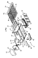
- Figs. 1-4 show an embodiment of table saw 10 according to one embodiment this invention.
- Table saw 10 is desirably used to cut materials, including, but not limited to, ceramic tile, porcelain tile, stone and glass.
- Table saw 10 can be used in either a wet-cut or dry cut method.
- the present invention is directed to table saw 10 including base 20, working table 40 and power tool 50.
- Working table 40 is slidably positioned on base 20.
- power tool 50 is mounted to or housed within base 20 in a removable fashion such that power tool 50 is separately operable outside the confines of table saw 10, for instance, if table saw 10 is no longer needed for a particular project.
- Base 20 is made or formed of a suitable lightweight yet durable material, such as a fabricated metal, an alloy material and/or a molded plastic material, such as, Acrylonitrile Butadiene Styrene (ABS) plastic.
- ABS Acrylonitrile Butadiene Styrene
- base 20 has suitable dimensions and weight to allow table saw 10 to be portable.
- base 20 can include center wall 22, first sidewall 24, second sidewall 26, a plurality of braces 28, center rail 30 and rear cover 32.
- First sidewall 24 and second sidewall 26 are each joined to a respective edge of center wall 22.
- the plurality of braces 28 span from first sidewall 24 to second sidewall 26 providing support and rigidity to base 20. This arrangement provides a light-weight, open structure.
- Center rail 30 is preferably positioned above center wall 22. According to a preferred embodiment of this invention, center rail 30 fits into groove 42 on an underside of working table 40 permitting working table 40 to slide in a cutting direction along a length of center rail 30 and a top of base 20 and with respect to cutting element 52.
- Table saw 10 preferably includes at least one guide bar 34. In the embodiment of Figs. 1-2 , a pair of guide bars 34 extend from each end of center rail 30, guide bars 34 are preferably connected to center rail 30 with a threaded connection, to permit attachment and removal, but may be connected in any other way known to one of ordinary skill in the art including, but not limited to a friction fit. Removable guide bars 34 permit table saw 10 to occupy a compact footprint when transported, stored or otherwise not in use.
- working table 40 may slide relative to base 20 along a combined length of center rail 30 and guide bar(s) 34.
- Guide bar 34 may further be stored within base 20 adding to the ease of portability and storage.
- center rail 30 and guide bars 34 are integrated into a single rail.
- a single guide bar extends from one side of center rail 30.
- Guide bar 34 and/or center rail 30 may comprise any desirable elongated shape and/or cross-section, including round, square, asymmetric, rectangular and/or any other desirable configuration.
- Working table 40 is positioned on the base and is preferably moveable along center rail 30 and/or guide bar 34 as it slides on base 20 towards and away-from cutting element 54 so as to permit the user to guide a work piece along table saw 10 and provide the desired cut.
- groove 42 and/or center rail 30 can include rollers or bearings to reduce friction and improve the slideabity of working table 40.
- working table 40 comprises a generally planar support surface 44 and slot 46 extending through at least a portion of working table 40.
- support surface 44 includes a first or front end portion and a second or back end portion and having or defining a work area.
- the work area provides support for a work piece, such as a wood, metal, stone or tile work piece.
- Support surface 44 is movable in the cutting direction with respect to base 20 and/or cutting element 54 to move the work piece towards cutting element 154 and pass the work piece through the work area to cut into and/or through the work piece using cutting element 154.
- Working table 40 is preferably made or formed of a suitable lightweight yet durable material, such as a fabricated metal, an alloy material and/or a molded plastic material, such as, Acrylonitrile Butadiene Styrene (ABS) plastic.
- a suitable lightweight yet durable material such as a fabricated metal, an alloy material and/or a molded plastic material, such as, Acrylonitrile Butadiene Styrene (ABS) plastic.
- ABS Acrylonitrile Butadiene Styrene
- working table 40 includes edge support 48, which is positioned on one edge of working table 40 and preferably perpendicular to slot 46.
- Edge support 48 provides a safe area for a user to place his/her hands while operating table saw 10.
- Edge support 48 can include a straight edge for lining up a tile to be cut.
- Edge support 48 can also further include a ruler including metric and/or English units for measuring a length on the material to be cut. The straight edge and the ruler allowing for repeatable and accurate cutting.
- table saw 10 includes power tool 50 removably mounted to base 20.
- Power tool 50 according to a preferred embodiment of this invention is preferably a hand tool having a separate utility apart from table saw 10, such as an angle grinder, a power sander, a drill or similar rotating tool.
- Power tool 50 preferably includes grip 52, a motor, power switch 53 and removable cutting element 54.
- Power tool 50 is preferably removably mounted to base 20 in a manner to facilitate easy removal and yet still maintain a sturdy connection with respect to base.
- Power tool 50 may be connected with respect to base 20 using set screws, tool-less fasteners, brackets and/or any other suitable attachment method for facilitating reproducible and solid attachment and also simple removal for stand alone use of power tool 50.
- Grip 52 facilitates using power tool 50 when removed from table saw 10 preferably allowing a user to safely handle power tool 50 away from cutting element 54 and allowing a user to counter-act any rotational forces that are transferred from the motor to the user when the cutting element 54 contacts a material to be cut, grinded and/or sanded.
- base 10 includes an opening, an access panel and/or a switch 38.
- the opening, the access panel and/or the switch 38 allow the user to activate/deactivate power switch 53 of power tool 50 while power tool 50 is mounted to and/or housed within base 10.
- Cutting elements 54 may be any suitable cutting element known to those skilled in the art and chosen according to a work piece material to be cut. Types of cutting element 54 can include, but not limited to, a circular blade, a standard blade, a drill bit or a cutting/grinding disk.
- the motor is preferably self-contained within power tool 50 and able to provide sufficient power to rotate cutting element 154 at a desired speed and/or with a desired torque.
- a height or distance of cutting element 54 extending through slot 46 is adjustable, as desired to cut into and/or through a tile or other work piece.
- power tool 50 may be secured to base 20 with an adjustable bracket (not shown).
- the adjustable bracket can provide vertical adjustment ofpower tool 50 and cutting element 54 relative to support surface 44.
- fixed brackets may be used to house power tool 50 permit removable attachment of power tool 50 to base 20.
- a cutting angle of cutting element 54 with respect to support surface 44 is also adjustable to cut the work piece at a desired cutting angle. For example to bevel an edge of a material.
- Table saw 10 can further include blade guard 36.
- Blade guard 36 is preferably connected to base 20 with a hinge on one end of blade guard 36. Blade guard 36 protects a user of table saw 10 by covering an exposed portion of cutting element 54 that extends through slot 46.
- table saw 10 preferably includes blade cover 60.
- blade cover 60 is mounted to center wall 22 and is composed of two parts 61, 63 which surround a portion of cutting element 54.
- Blade cover 60 can further includes inlet channel 62 and outlet channel 64.
- blade cover 60 may be partially submerged in water in tray 66, the rotation of cutting element 54 draws water from tray 66 through inlet channel 62 to cool cutting element 54 as it cuts a material.
- cutting element 54 cuts a material, dust and chips are created.
- the chips and dust, along with water, may be discharged from the blade cover 60 via outlet channel and preferably away from the water in tray 66 to prevent contaminating the water with dust and/or chips.
- Fig. 5 shows table saw 10 further including diagonal cutting attachment 70 positioned on support surface 44 and preferably joined to edge support 48 with a bracket.
- Diagonal attachment 70 supports a workpiece at an angle to edge support 48 allowing the work piece to be cut at a non-perpendicular angle.
- Fig. 6 shows table saw 10 further including miter block 80 positioned on support surface 44.
- Miter block 80 supports a work piece at angle to support surface 44 and/or cutting element 54 allowing the work piece to be cut at a non-perpendicular angle.
- miter block is adjustable to a plurality of angle.
Landscapes
- Engineering & Computer Science (AREA)
- Mechanical Engineering (AREA)
- Life Sciences & Earth Sciences (AREA)
- Wood Science & Technology (AREA)
- Forests & Forestry (AREA)
- Mining & Mineral Resources (AREA)
- Processing Of Stones Or Stones Resemblance Materials (AREA)
- Sawing (AREA)
Applications Claiming Priority (1)
| Application Number | Priority Date | Filing Date | Title |
|---|---|---|---|
| US4848608P | 2008-04-28 | 2008-04-28 |
Publications (2)
| Publication Number | Publication Date |
|---|---|
| EP2113354A2 true EP2113354A2 (de) | 2009-11-04 |
| EP2113354A3 EP2113354A3 (de) | 2009-12-23 |
Family
ID=40941704
Family Applications (1)
| Application Number | Title | Priority Date | Filing Date |
|---|---|---|---|
| EP20090005899 Withdrawn EP2113354A3 (de) | 2008-04-28 | 2009-04-28 | Tischsäge |
Country Status (2)
| Country | Link |
|---|---|
| US (1) | US20090266350A1 (de) |
| EP (1) | EP2113354A3 (de) |
Cited By (2)
| Publication number | Priority date | Publication date | Assignee | Title |
|---|---|---|---|---|
| WO2013072761A1 (en) * | 2011-11-18 | 2013-05-23 | Robert Bosch Gmbh | Tile saw with removable table |
| EP3181316A1 (de) * | 2015-12-16 | 2017-06-21 | Black & Decker Inc. | Fliesensäge |
Families Citing this family (12)
| Publication number | Priority date | Publication date | Assignee | Title |
|---|---|---|---|---|
| CN201659635U (zh) * | 2010-03-26 | 2010-12-01 | 南京搏峰电动工具有限公司 | 石材切割机 |
| CN103963169B (zh) * | 2013-02-02 | 2016-04-20 | 南京搏峰电动工具有限公司 | 台锯 |
| CN104786373B (zh) * | 2014-01-20 | 2017-01-04 | 南京搏峰电动工具有限公司 | 台锯 |
| CN104275749B (zh) * | 2013-07-02 | 2016-04-27 | 南京德朔实业有限公司 | 石材切割机 |
| US10583583B2 (en) | 2016-03-01 | 2020-03-10 | Tti (Macao Commercial Offshore) Limited | Table joining mechanism |
| TWI621513B (zh) * | 2016-03-18 | 2018-04-21 | 力山工業股份有限公司 | 磁磚切割機之收納式擋水裝置 |
| CN106881657B (zh) * | 2017-01-11 | 2019-01-01 | 泰山学院 | 一种工程石材的电气自动化切割系统 |
| US10252444B2 (en) * | 2017-04-14 | 2019-04-09 | Tti (Macao Commercial Offshore) Limited | Tile saw |
| CN114654592A (zh) * | 2020-12-07 | 2022-06-24 | 南京泉峰科技有限公司 | 切割工具 |
| CN114654017A (zh) * | 2020-12-07 | 2022-06-24 | 南京泉峰科技有限公司 | 切割工具 |
| CN114654021A (zh) * | 2020-12-07 | 2022-06-24 | 南京泉峰科技有限公司 | 切割工具 |
| WO2022226271A1 (en) * | 2021-04-22 | 2022-10-27 | Black & Decker, Inc. | Tile saw |
Family Cites Families (22)
| Publication number | Priority date | Publication date | Assignee | Title |
|---|---|---|---|---|
| US2444598A (en) * | 1947-06-16 | 1948-07-06 | Wilfred C Eyles | Tile-sawing machine |
| US2652863A (en) * | 1948-05-11 | 1953-09-22 | Edward E Grabinski | Power-driven table tool with portable vertical-shaft motor |
| US3008462A (en) * | 1960-07-29 | 1961-11-14 | Alonzo L Williams | Processing saw for cutting and processing rock or stone material |
| FR1361904A (fr) * | 1963-01-22 | 1964-05-29 | Dispositif destiné à permettre l'utilisation des polisseuses électriques portatives en tant que débiteuses à disque diamanté, à l'usage des carreleurs | |
| FR2497717A1 (fr) * | 1981-01-13 | 1982-07-16 | Goubaud Michel | Scie a lame de coupe circulaire |
| US4428159A (en) * | 1981-07-29 | 1984-01-31 | Sigetich John D | Portable, direct drive abrasive saw |
| US4483573A (en) * | 1982-07-09 | 1984-11-20 | Keller David L | Tool adapter for working table top storage cabinet |
| EP0253032A1 (de) * | 1986-07-11 | 1988-01-20 | SOCIETE DE MECANIQUE GENERALE (SMG) Société Anonyme dite: | Konstruktionsmaterialienschneidemaschine |
| US4976251A (en) * | 1989-06-28 | 1990-12-11 | Smith Allen L | Tile saw apparatus and method |
| US5832913A (en) * | 1995-05-30 | 1998-11-10 | Arends; William R. | Tile saw accessory |
| US5676124A (en) * | 1996-01-11 | 1997-10-14 | K Diamond Inc. | Ceramic and masonry power saw |
| US7823575B2 (en) * | 1998-11-02 | 2010-11-02 | Black & Decker Inc. | Tile saw |
| US6263866B1 (en) * | 2000-01-18 | 2001-07-24 | Wen-Hai Tsao | Stone cutter |
| US6347624B1 (en) * | 2000-11-17 | 2002-02-19 | Porter-Cable/Delta | Tile saw |
| US6494198B1 (en) * | 2001-04-24 | 2002-12-17 | Yuehting Chen | Stone cutter |
| GB0119680D0 (en) * | 2001-08-11 | 2001-10-03 | Turner Intellect Property Ltd | Tile cutter |
| US6752139B2 (en) * | 2002-08-13 | 2004-06-22 | Wy Peron Lee | Worktable for cutting machine |
| US6775917B1 (en) * | 2003-03-20 | 2004-08-17 | James L. Campbell | Adjustable angle cutting jig device and method of using |
| US6932074B2 (en) * | 2003-11-12 | 2005-08-23 | Motomax Electric Co., Ltd. | Tile positioning device for a tile cutting machine |
| US7066068B1 (en) * | 2004-09-10 | 2006-06-27 | Larry Caldwell | Table saw |
| US7350517B2 (en) * | 2005-12-06 | 2008-04-01 | Pedro Perez | Tile saw guide apparatus |
| US7819112B2 (en) * | 2007-01-25 | 2010-10-26 | M & R Manufacturing | Stone cutting device |
-
2009
- 2009-04-28 US US12/430,969 patent/US20090266350A1/en not_active Abandoned
- 2009-04-28 EP EP20090005899 patent/EP2113354A3/de not_active Withdrawn
Cited By (4)
| Publication number | Priority date | Publication date | Assignee | Title |
|---|---|---|---|---|
| WO2013072761A1 (en) * | 2011-11-18 | 2013-05-23 | Robert Bosch Gmbh | Tile saw with removable table |
| US8677987B2 (en) | 2011-11-18 | 2014-03-25 | Robert Bosch Gmbh | Tile saw with removable table |
| EP3181316A1 (de) * | 2015-12-16 | 2017-06-21 | Black & Decker Inc. | Fliesensäge |
| US10603819B2 (en) | 2015-12-16 | 2020-03-31 | Black & Decker Inc. | Tile saw |
Also Published As
| Publication number | Publication date |
|---|---|
| US20090266350A1 (en) | 2009-10-29 |
| EP2113354A3 (de) | 2009-12-23 |
Similar Documents
| Publication | Publication Date | Title |
|---|---|---|
| US20090266350A1 (en) | Table saw | |
| US11458648B2 (en) | Power tool cutting apparatus | |
| US6932073B2 (en) | Power tool work table | |
| EP2869975B1 (de) | Elektrowerkzeug | |
| US9027450B1 (en) | Work piece cutting apparatus | |
| US8776656B2 (en) | Circular and miter box saw | |
| US10464231B2 (en) | Miter saw with improved carrying mode | |
| US8910552B2 (en) | Movable saw apparatus and method | |
| US4742743A (en) | Radial saw accessory for preventing sawdust buildup | |
| US20050051015A1 (en) | Power tool work table | |
| EP4326516A1 (de) | Fliesensäge | |
| US20030145706A1 (en) | Guide for power tool | |
| RU54554U1 (ru) | Пильный станок | |
| EP2017046B1 (de) | Tragbare Hobelmaschine | |
| CN201511419U (zh) | 一种多功能木工机械 | |
| RU53209U1 (ru) | Торцово-усовочная пила | |
| CN223235192U (zh) | 多功能斜切锯 | |
| CN201755697U (zh) | 切割机 | |
| RU53208U1 (ru) | Дисковый пильный станок (варианты) | |
| CN206796040U (zh) | 胶合木链锯切割靠模辅助设备 | |
| US20120192693A1 (en) | Cutting machine | |
| CN119077040A (zh) | 多功能斜切锯 | |
| CA2494789A1 (en) | Portable power-saw guide strip for use with folding work benches | |
| FI82624B (fi) | Faestmekanism foer en hjaelpanordning av en handcirkelsaog. | |
| CN108436571A (zh) | 一种铝塑板稳定切割装置 |
Legal Events
| Date | Code | Title | Description |
|---|---|---|---|
| PUAI | Public reference made under article 153(3) epc to a published international application that has entered the european phase |
Free format text: ORIGINAL CODE: 0009012 |
|
| AK | Designated contracting states |
Kind code of ref document: A2 Designated state(s): AT BE BG CH CY CZ DE DK EE ES FI FR GB GR HR HU IE IS IT LI LT LU LV MC MK MT NL NO PL PT RO SE SI SK TR |
|
| PUAL | Search report despatched |
Free format text: ORIGINAL CODE: 0009013 |
|
| AK | Designated contracting states |
Kind code of ref document: A3 Designated state(s): AT BE BG CH CY CZ DE DK EE ES FI FR GB GR HR HU IE IS IT LI LT LU LV MC MK MT NL NO PL PT RO SE SI SK TR |
|
| STAA | Information on the status of an ep patent application or granted ep patent |
Free format text: STATUS: THE APPLICATION IS DEEMED TO BE WITHDRAWN |
|
| 18D | Application deemed to be withdrawn |
Effective date: 20100624 |