EP2113368A2 - Vorrichtung zum Blasformen - Google Patents
Vorrichtung zum Blasformen Download PDFInfo
- Publication number
- EP2113368A2 EP2113368A2 EP09004872A EP09004872A EP2113368A2 EP 2113368 A2 EP2113368 A2 EP 2113368A2 EP 09004872 A EP09004872 A EP 09004872A EP 09004872 A EP09004872 A EP 09004872A EP 2113368 A2 EP2113368 A2 EP 2113368A2
- Authority
- EP
- European Patent Office
- Prior art keywords
- cooling
- hollow body
- air
- blow
- cooling device
- Prior art date
- Legal status (The legal status is an assumption and is not a legal conclusion. Google has not performed a legal analysis and makes no representation as to the accuracy of the status listed.)
- Granted
Links
Images

Classifications
-
- B—PERFORMING OPERATIONS; TRANSPORTING
- B29—WORKING OF PLASTICS; WORKING OF SUBSTANCES IN A PLASTIC STATE IN GENERAL
- B29C—SHAPING OR JOINING OF PLASTICS; SHAPING OF MATERIAL IN A PLASTIC STATE, NOT OTHERWISE PROVIDED FOR; AFTER-TREATMENT OF THE SHAPED PRODUCTS, e.g. REPAIRING
- B29C49/00—Blow-moulding, i.e. blowing a preform or parison to a desired shape within a mould; Apparatus therefor
- B29C49/42—Component parts, details or accessories; Auxiliary operations
- B29C49/64—Heating or cooling preforms, parisons or blown articles
- B29C49/6409—Thermal conditioning of preforms
- B29C49/6463—Thermal conditioning of preforms by contact heating or cooling, e.g. mandrels or cores specially adapted for heating or cooling preforms
- B29C49/6465—Cooling
-
- B—PERFORMING OPERATIONS; TRANSPORTING
- B29—WORKING OF PLASTICS; WORKING OF SUBSTANCES IN A PLASTIC STATE IN GENERAL
- B29C—SHAPING OR JOINING OF PLASTICS; SHAPING OF MATERIAL IN A PLASTIC STATE, NOT OTHERWISE PROVIDED FOR; AFTER-TREATMENT OF THE SHAPED PRODUCTS, e.g. REPAIRING
- B29C49/00—Blow-moulding, i.e. blowing a preform or parison to a desired shape within a mould; Apparatus therefor
- B29C49/08—Biaxial stretching during blow-moulding
- B29C49/16—Biaxial stretching during blow-moulding using pressure difference for pre-stretching, e.g. pre-blowing
-
- B—PERFORMING OPERATIONS; TRANSPORTING
- B29—WORKING OF PLASTICS; WORKING OF SUBSTANCES IN A PLASTIC STATE IN GENERAL
- B29C—SHAPING OR JOINING OF PLASTICS; SHAPING OF MATERIAL IN A PLASTIC STATE, NOT OTHERWISE PROVIDED FOR; AFTER-TREATMENT OF THE SHAPED PRODUCTS, e.g. REPAIRING
- B29C49/00—Blow-moulding, i.e. blowing a preform or parison to a desired shape within a mould; Apparatus therefor
- B29C49/42—Component parts, details or accessories; Auxiliary operations
- B29C49/4284—Means for recycling or reusing auxiliaries or materials, e.g. blowing fluids or energy
- B29C49/42845—Recycling or reusing of fluid, e.g. pressure
-
- B—PERFORMING OPERATIONS; TRANSPORTING
- B29—WORKING OF PLASTICS; WORKING OF SUBSTANCES IN A PLASTIC STATE IN GENERAL
- B29C—SHAPING OR JOINING OF PLASTICS; SHAPING OF MATERIAL IN A PLASTIC STATE, NOT OTHERWISE PROVIDED FOR; AFTER-TREATMENT OF THE SHAPED PRODUCTS, e.g. REPAIRING
- B29C49/00—Blow-moulding, i.e. blowing a preform or parison to a desired shape within a mould; Apparatus therefor
- B29C49/42—Component parts, details or accessories; Auxiliary operations
- B29C49/64—Heating or cooling preforms, parisons or blown articles
- B29C49/6604—Thermal conditioning of the blown article
- B29C2049/6606—Cooling the article
-
- B—PERFORMING OPERATIONS; TRANSPORTING
- B29—WORKING OF PLASTICS; WORKING OF SUBSTANCES IN A PLASTIC STATE IN GENERAL
- B29C—SHAPING OR JOINING OF PLASTICS; SHAPING OF MATERIAL IN A PLASTIC STATE, NOT OTHERWISE PROVIDED FOR; AFTER-TREATMENT OF THE SHAPED PRODUCTS, e.g. REPAIRING
- B29C49/00—Blow-moulding, i.e. blowing a preform or parison to a desired shape within a mould; Apparatus therefor
- B29C49/42—Component parts, details or accessories; Auxiliary operations
- B29C49/64—Heating or cooling preforms, parisons or blown articles
- B29C49/6604—Thermal conditioning of the blown article
- B29C2049/6606—Cooling the article
- B29C2049/6676—Cooling the article the medium being oriented towards special areas of the blown article
- B29C2049/6692—Bottom area
-
- B—PERFORMING OPERATIONS; TRANSPORTING
- B29—WORKING OF PLASTICS; WORKING OF SUBSTANCES IN A PLASTIC STATE IN GENERAL
- B29C—SHAPING OR JOINING OF PLASTICS; SHAPING OF MATERIAL IN A PLASTIC STATE, NOT OTHERWISE PROVIDED FOR; AFTER-TREATMENT OF THE SHAPED PRODUCTS, e.g. REPAIRING
- B29C49/00—Blow-moulding, i.e. blowing a preform or parison to a desired shape within a mould; Apparatus therefor
- B29C49/42—Component parts, details or accessories; Auxiliary operations
- B29C49/78—Measuring, controlling or regulating
- B29C49/783—Measuring, controlling or regulating blowing pressure
- B29C2049/7831—Measuring, controlling or regulating blowing pressure characterised by pressure values or ranges
-
- B—PERFORMING OPERATIONS; TRANSPORTING
- B29—WORKING OF PLASTICS; WORKING OF SUBSTANCES IN A PLASTIC STATE IN GENERAL
- B29C—SHAPING OR JOINING OF PLASTICS; SHAPING OF MATERIAL IN A PLASTIC STATE, NOT OTHERWISE PROVIDED FOR; AFTER-TREATMENT OF THE SHAPED PRODUCTS, e.g. REPAIRING
- B29C49/00—Blow-moulding, i.e. blowing a preform or parison to a desired shape within a mould; Apparatus therefor
- B29C49/42—Component parts, details or accessories; Auxiliary operations
- B29C49/78—Measuring, controlling or regulating
- B29C49/783—Measuring, controlling or regulating blowing pressure
- B29C2049/7832—Blowing with two or more pressure levels
-
- B—PERFORMING OPERATIONS; TRANSPORTING
- B29—WORKING OF PLASTICS; WORKING OF SUBSTANCES IN A PLASTIC STATE IN GENERAL
- B29C—SHAPING OR JOINING OF PLASTICS; SHAPING OF MATERIAL IN A PLASTIC STATE, NOT OTHERWISE PROVIDED FOR; AFTER-TREATMENT OF THE SHAPED PRODUCTS, e.g. REPAIRING
- B29C49/00—Blow-moulding, i.e. blowing a preform or parison to a desired shape within a mould; Apparatus therefor
- B29C49/28—Blow-moulding apparatus
- B29C49/30—Blow-moulding apparatus having movable moulds or mould parts
- B29C49/36—Blow-moulding apparatus having movable moulds or mould parts rotatable about one axis
-
- B—PERFORMING OPERATIONS; TRANSPORTING
- B29—WORKING OF PLASTICS; WORKING OF SUBSTANCES IN A PLASTIC STATE IN GENERAL
- B29C—SHAPING OR JOINING OF PLASTICS; SHAPING OF MATERIAL IN A PLASTIC STATE, NOT OTHERWISE PROVIDED FOR; AFTER-TREATMENT OF THE SHAPED PRODUCTS, e.g. REPAIRING
- B29C49/00—Blow-moulding, i.e. blowing a preform or parison to a desired shape within a mould; Apparatus therefor
- B29C49/42—Component parts, details or accessories; Auxiliary operations
- B29C49/4284—Means for recycling or reusing auxiliaries or materials, e.g. blowing fluids or energy
- B29C49/42845—Recycling or reusing of fluid, e.g. pressure
- B29C49/42855—Blowing fluids, e.g. reducing fluid consumption
-
- Y—GENERAL TAGGING OF NEW TECHNOLOGICAL DEVELOPMENTS; GENERAL TAGGING OF CROSS-SECTIONAL TECHNOLOGIES SPANNING OVER SEVERAL SECTIONS OF THE IPC; TECHNICAL SUBJECTS COVERED BY FORMER USPC CROSS-REFERENCE ART COLLECTIONS [XRACs] AND DIGESTS
- Y02—TECHNOLOGIES OR APPLICATIONS FOR MITIGATION OR ADAPTATION AGAINST CLIMATE CHANGE
- Y02P—CLIMATE CHANGE MITIGATION TECHNOLOGIES IN THE PRODUCTION OR PROCESSING OF GOODS
- Y02P70/00—Climate change mitigation technologies in the production process for final industrial or consumer products
- Y02P70/10—Greenhouse gas [GHG] capture, material saving, heat recovery or other energy efficient measures, e.g. motor control, characterised by manufacturing processes, e.g. for rolling metal or metal working
Definitions
- the invention relates to a device for blow molding of hollow bodies made of plastic of the type explained in the preamble of claim 1.
- Such a device is known from DE 10 2004 014 653 A1 known.
- the known device comprises a blow molding device in the form of a rotating blow module, in which a plurality of blow molds are provided.
- the blow molds are connected to a plurality of compressed air reservoirs for introducing blown air at different pressures.
- first heated preforms are inserted into the respective blow molds and expanded by applying an internal pressure by introducing compressed air at a first pressure (pre-blowing phase).
- compressed air is introduced under a second, higher pressure, possibly accompanied by stretching by means of a stretch rod, whereby the preform is applied to the walls of the blow mold and assumes its contour.
- compressed air at a third, even higher pressure can be introduced, which completely expresses the hollow body and cools.
- the compressed air used is partially recycled, ie, each supplied to the compressed air reservoir whose pressure is below the process pressure currently being used, which may be, for example, the compressed air reservoir for final blowing or a working air accumulator which collects working air for use in other manufacturing processes.
- the remaining compressed air which due to the lack of pressure difference can no longer flow into any of the storage tanks, is released to the atmosphere via a silencer.
- the most hollow body however, have no uniformly thick wall. For example, in the case of bottles or glasses, the bottom is reinforced in order to achieve greater strength there.
- the cooling device is integrated in a conveying path which conveys the hollow bodies from the blow molding device to a further processing machine, that is to say for example a filling machine.
- the cooling device contains a distributor, which is arranged adjacent to the bottom region of the conveyed hollow body.
- the cooling medium used is preferably liquid, in particular sterile water; However, the use of air is also possible. However, the cooling medium is provided separately, which requires additional effort.
- the invention has for its object to provide a device for blow molding of hollow bodies, with the design and manufacturing technology simple way, a partial cooling of areas of the hollow body is possible.
- exhaust air which is normally no longer usable and is discharged into the environment, can be used for cooling individual regions of the hollow body.
- the exhaust air has the advantage that it is very cool, dry and oil-free by the relaxation and thus optimally suitable for use for targeted, partial aftercooling of certain (problem) areas of the hollow body.
- the cooling device is preferably arranged outside the blow molding device, but may also be integrated into the blow molding device.
- the exhaust air is preferably first collected in a plenum before it is fed to the cooling device.
- the exhaust air is diverted before discharge into the atmosphere, so that the exhaust air can also, as usual, be relieved to the atmosphere, if cooling is not necessary.
- the supply of the cooling device preferably takes place from a storage loop in the rotary distributor.
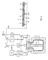
- Fig. 1 shows a system 1 for handling hollow bodies 2 ( Fig. 2 ) made of plastic, in the illustrated embodiment, these are beverage bottles.
- the plant 1 contains a device 3 for blow molding the hollow body 2, which is connected via a conveying path 4 with a further processing machine 5, for example a filling device.
- the described blow molding device 3 is similar to the blow molding of the DE 10 2004 014 653 A1 , which is hereby incorporated by reference.
- the blow molding apparatus 3 includes a rotary blowing module 6 having a plurality of blowing stations 7 in which blow molds 7a are provided.
- the blowing module 6 is supplied via a Schoblas Kunststoff für 8 with compressed air, which passes through a rotary distributor 9 in the module 6.
- There are a plurality of media reservoirs 10, 11 and 12 are provided, which are supplied via the Hauptblas Kunststoff effet 8.
- a Vorblasmedien amid 11, a Fertigblasmedien amid 10 and a flushing and cooling air media storage 12 are shown for use in the blowing process, which are connected via corresponding valves in a known manner with the compressed air main supply 8 in connection.
- the memory 10 to 12 are each held on its own, differing from the other memory pressure, the pressure in the pre-blower 11 between 2 to 20 bar, the pressure in the finished blower 10 between 15 to 45 bar, and the pressure in the purge and cold storage 12 is between 30 to 45 bar.
- the blow mold 7a has an inner cavity which corresponds to the outer contour of the desired hollow body 2.
- the tuyere 7a is closed with a tuyere 14 containing blown air passageways 15, 16 into the cavity of the tuyere 7a and a passageway not shown through which a stretch rod 17 can be inserted into the interior of the tuyere 7a.
- the stretch rod 17 is also provided with air outlet openings 17a.
- the passage connection 15 is connected via a line 15a and corresponding valves with both the pre-blower 11 and the Fertigblas immediately 10, in such a way that from the pre-blow 11 air can be introduced into the blow mold 7a. From the finished blower 10 both the pre-blower 11 and the passage connection 15 can be supplied with compressed air in the blow mold 7a.
- the valves connected to the passage connection 15 also allow recirculation of compressed air from the blow mold 7a into the finished blower 11 at lower pressure, so that the blown air can be recycled as long as the pressure in the blow mold is higher than the pressure in that store, in which the used blown air to be transferred.
- the flushing and cooling air accumulator 12 again via a valve, communicates with the stretching rod 17 and supplies it with flushing and cooling air at the end of the blowing process.
- the passage connection 16 is connected via a line 16a with a fourth medium reservoir 13 in connection, which is designed as a working air reservoir and collects working air for other processes than the blowing of the hollow body 2 and provides.
- the line 16a further leads via a branch and in turn via a corresponding valve and preferably via a fifth memory 18 to a pressure discharge device into the atmosphere, which takes place via a silencer 19.
- the fourth and the fifth medium storage 13, 18 are arranged within the rotary distributor 9, but may also be provided outside.
- the muffler 19 is preferably arranged outside of the rotary distributor 9.
- All memories 10 to 13 and 18 are preferably designed as memory ring lines (s. Fig. 1 ).
- a preheated preform is first introduced into the blow mold 7a, and then the blow nozzle 14 is placed. Then, pre-blowing air is introduced from the pre-blowing medium reservoir 11 into the interior of the preform so that the preform expands. Subsequently, the finished blowing with blowing air from the finished blower 10 is carried out under an increased pressure. At the same time, the stretch rod 17 can be inserted into the hollow body and supports the stretching. Upon completion of the Fertigblasvorgangs the hollow body 2 has substantially its final outer shape, but the contours are not yet fully pronounced.
- the Exhaust air line 16a and the Exhaust air reservoir 18 lead out of the rotary distributor 9 and are outside of the blow molding device 3 via a line 20a with a cooling device 20 in combination, which is associated with the conveyor 4.
- the cooling device 20 is structurally similar to the cooling device of the DE 20 2007 008 120 U1 , which is hereby incorporated by reference. Accordingly, the cooling device 20 includes a conveying path, which with lateral walls 21 (top view in FIG Fig. 2 ) is limited and not shown moving means for the moving between the walls 21 in the direction of the treatment machine 5 hollow body 2 is provided.
- openings 22 tube 23 which via the cooling air line 20 a with that Air is supplied, which is still in the interior of the hollow body 2 after the blowing process and possibly after the recycling process in the finished blower 10 or after the filling of the working memory.
- a certain supply can be provided.
- the openings 22 which are preferably not formed as nozzles, but as a simple flow openings, the remaining after blowing, cool, dry and oil-free air is blown from the outside against the bottom of the hollow body 2, which is thereby additionally partially cooled, so that There is no danger of deformation, even if there is a greater material thickness than in the other areas of the hollow body 2 is present.
- the hollow body 2 are brought to a temperature which is low enough so that the wall of the hollow body 2 can no longer deform during the subsequent handling of the hollow body 2, for example when filling in the filler 5.
- the exhaust air can be discharged in a conventional manner via the muffler 19 to the atmosphere.
- the cooling device may also contain other structural configurations, for example, individual nozzles or a cooled by the air surface or the like.
- the cooling air storage medium does not necessarily have to be present, as long as sufficient air can be provided.
- the cooling device according to the invention using exhaust air can also be combined with other known blow molding devices and with other methods for their operation, provided that these methods produce exhaust air.
Landscapes
- Engineering & Computer Science (AREA)
- Manufacturing & Machinery (AREA)
- Mechanical Engineering (AREA)
- Life Sciences & Earth Sciences (AREA)
- Sustainable Development (AREA)
- Physics & Mathematics (AREA)
- Thermal Sciences (AREA)
- Blow-Moulding Or Thermoforming Of Plastics Or The Like (AREA)
Abstract
Description
- Die Erfindung bezieht sich auf eine Vorrichtung zum Blasformen von Hohlkörpern aus Kunststoff der im Oberbegriff von Anspruch 1 erläuterten Art.
- Eine derartige Vorrichtung ist aus der
DE 10 2004 014 653 A1 bekannt. Die bekannte Vorrichtung enthält eine Blasformeinrichtung in Form eines rotierenden Blasmoduls, in dem eine Vielzahl von Blasformen vorgesehen sind. Die Blasformen sind mit einer Mehrzahl von Druckluftspeichern zum Einleiten von Blasluft mit unterschiedlichen Drücken verbunden. Zum Herstellen der Hohlkörper in den Blasformen werden zunächst erwärmte Vorformlinge in die jeweiligen Blasformen eingesetzt und durch Anlegen eines Innendrucks durch Einleiten von Druckluft unter einem ersten Druck aufgeweitet (Vorblasphase). Anschließend wird Druckluft unter einem zweiten, höheren Druck eingeleitet, ggf. begleitet durch ein Recken mit Hilfe einer Reckstange, wodurch sich der Vorformling an die Wände der Blasform anlegt und deren Kontur annimmt. Schließlich kann Druckluft unter einem dritten, noch höheren Druck (Spül-und Kühlphase) eingeleitet werden, die den Hohlkörper vollständig ausprägt und kühlt. Die verwendete Druckluft wird zum Teil recycelt, d.h. jeweils demjenigen Druckluftspeicher zugeführt, dessen Druck unter dem gerade eingesetzten Prozessdruck liegt, was beispielsweise der Druckluftspeicher zum Fertigblasen oder ein Arbeitsluftspeicher sein kann, der Arbeitsluft zur Verwendung in anderen Fertigungsprozessen sammelt. Die restlliche Druckluft, die wegen des fehlenden Druckunterschiedes nicht mehr in irgendeinen der Speicher fließen kann, wird über einen Schalldämpfer an die Atmosphäre entlassen. Die meister Hohlkörper haben jedoch keine gleichmäßig dicke Wandung. So ist beispielsweise bei Flaschen oder Gläsern der Boden verstärkt, um dort eine höhere Festigkeit zu erzielen. Dadurch befindet sich jedoch am Boden mehr Material, das zum vollständigen Abkühlen bis auf einen Zustand, bei dem keine unbeabsichtigte Verformung mehr stattfinden kann, eine längere Kühlzeit und/oder eine intensivere Kühlung erfordert, die unter Umständen durch das beschriebene Kühlen von innen nicht oder nicht in einer akzeptablen Prozesszeit erreicht werden kann. - Um eine intensivere Kühlung zu erreichen, wird beispielsweise in der
DE 20 2007 008 120 U1 vorgeschlagen, Bereiche mit höherer Wandstärke, also beispielsweise den Boden von Gefäßen, durch eine Kühleinrichtung zu führen, die Bereiche höherer Wandstärke gezielt zusätzlich von außen kühlt. Die Kühleinrichtung ist in eine Förderstrecke integriert, die die Hohlkörper aus der Blasformeinrichtung zu einer Weiterbehandlungsmaschine, also beispielsweise einer Befüllmaschine, fördert. Die Kühleinrichtung enthält einen Verteiler, der benachbart zum Bodenbereich der geförderten Hohlkörper angeordnet ist. Als Kühlmedium wird bevorzugt Flüssigkeit, insbesondere Sterilwasser, verwendet; der Einsatz von Luft ist jedoch auch möglich. Das Kühlmedium wird jedoch gesondert bereitgestellt, was einen zusätzlichen Aufwand erfordert. - Der Erfindung liegt die Aufgabe zugrunde, eine Vorrichtung zum Blasformen von Hohlkörpern zu schaffen, mit der auf konstruktiv und fertigungstechnisch einfache Weise eine partielle Kühlung von Bereichen des Hohlkörpers möglich ist.
- Die Aufgabe wird durch die im Anspruch 1 angegebenen Merkmale gelöst.
- Durch die erfindungsgemäße Ausgestaltung kann Exhaustluft, die normalerweise nicht mehr zu verwenden ist und in die Umgebung abgelassen wird, zum Kühlen einzelner Bereiche des Hohlkörpers eingesetzt werden. Die Exhaustluft hat den Vorteil, dass sie durch die Entspannung sehr kühl, trocken und ölfrei ist und sich dadurch optimal für den Einsatz zum gezielten, partiellen Nachkühlen von bestimmten (Problem-)Bereichen des Hohlkörpers eignet.
- Vorteilhafte Weiterbildungen der Erfindung sind den Unteransprüchen zu entnehmen.
- Die Kühleinrichtung ist bevorzugt außerhalb der Blasformeinrichtung angeordnet, kann jedoch auch in die Blasformeinrichtung integriert sein.
- Die Exhaustluft wird bevorzugt zunächst in einem Sammelraum gesammelt, bevor sie der Kühleinrichtung zugeführt wird.
- Bevorzugt wird die Exhaustluft vor einer Ableitung in die Atmosphäre abgezweigt, so dass die Exhaustluft auch, wie üblich, in die Atmosphäre entlastet werden kann, falls eine Kühlung nicht notwendig ist.
- Beim Einsatz der Erfindung in einer Blasformeinrichtung mit einem rotierenden Blasmodul erfolgt die Versorgung der Kühleinrichtung bevorzugt aus einer Speicher-Ringleitung im Drehverteiler.
- Ein Ausführungsbeispiel der Erfindung wird nachfolgend anhand der Zeichnungen näher erläutert.
- Es zeigen:
- Fig. 1
- eine Blasformanlage mit der erfindungsgemäßen Vorrichtung in stark schematisierter Darstellung, und
- Fig. 2
- Einzelheiten der erfindungsgemäßen Vorrichtung in stark schematisierter Darstellung.
-
Fig. 1 zeigt eine Anlage 1 zur Handhabung von Hohlkörpern 2 (Fig. 2 ) aus Kunststoff, im dargestellten Ausführungsbeispiel sind dies Getränkeflaschen. Die Anlage 1 enthält eine Vorrichtung 3 zum Blasformen der Hohlkörper 2, die über eine Förderstrecke 4 mit einer Weiterbehandlungsmaschine 5, beispielsweise einer Befülleinrichtung, verbunden ist. Die beschriebene Blasformeinrichtung 3 ähnelt der Blasformeinrichtung derDE 10 2004 014 653 A1 , auf die hiermit Bezug genommen wird. - Die Blasformeinrichtung 3 enthält ein rotierendes Blasmodul 6, das eine Vielzahl von Blasstationen 7 aufweist, in denen Blasformen 7a vorgesehen sind. Das Blasmodul 6 wird über eine Hauptblasluftleitung 8 mit Druckluft versorgt, die über einen Drehverteiler 9 in das Modul 6 gelangt. Es sind eine Vielzahl von Medienspeichern 10, 11 und 12 vorgesehen, die über die Hauptblasluftleitung 8 versorgt werden. Im dargestellten Ausführungsbeispiel sind zum Einsatz im Blasvorgang ein Vorblasmedienspeicher 11, ein Fertigblasmedienspeicher 10 und ein Spül- und Kühlluftmedienspeicher 12 dargestellt, die über entsprechende Ventile in bekannter Weise mit der Drucklufthauptversorgung 8 in Verbindung stehen. Die Speicher 10 bis 12 werden jeweils auf einen eigenen, vom anderen Speicher sich unterscheidenden Druck gehalten, wobei der Druck im Vorblasspeicher 11 zwischen 2 bis 20 bar, der Druck im Fertigblasspeicher 10 zwischen 15 bis 45 bar, und der Druck im Spül- und Kühlblasspeicher 12 zwischen 30 bis 45 bar beträgt.
- Die Blasform 7a weist einen Innenhohlraum auf, der der Außenkontur des gewünschten Hohlkörpers 2 entspricht. Die Blasform 7a wird mit einer Blasdüse 14 verschlossen, die Durchlassverbindungen 15, 16 für Blasluft in den Hohlraum der Blasform 7a enthält, sowie eine nicht gezeichnete Durchlassverbindung aufweist, durch die eine Reckstange 17 in das Innere der Blasform 7a eingeführt werden kann. Die Reckstange 17 ist ebenfalls mit Luftauslassöffnungen 17a versehen.
- Die Durchlassverbindung 15 ist über eine Leitung 15a und entsprechende Ventile sowohl mit dem Vorblasspeicher 11 als auch dem Fertigblasspeicher 10 verbunden, und zwar derart, dass aus dem Vorblasspeicher 11 Luft in die Blasform 7a eingeleitet werden kann. Aus dem Fertigblasspeicher 10 kann sowohl der Vorblasspeicher 11 als auch die Durchlassverbindung 15 in die Blasform 7a mit Druckluft versorgt werden. Die mit der Durchlassverbindung 15 verbundenen Ventile erlauben jedoch auch ein Rückführen von Druckluft aus der Blasform 7a in den Fertigblasspeicher 11 mit niedrigerem Druck, so dass die Blasluft solange recycelt werden kann, solange der Druck in der Blasform höher ist als der Druck in demjenigen Speicher, in den die gebrauchte Blasluft überführt werden soll.
- Der Spül- und Kühlluftspeicher 12 steht, wiederum über ein Ventil, mit der Reckstange 17 in Verbindung und versorgt diese mit Spül- und Kühlluft am Ende des Blasvorgangs.
- Die Durchlassverbindung 16 steht über eine Leitung 16a mit einem vierten Mediumspeicher 13 in Verbindung, der als Arbeitsluftspeicher ausgebildet ist und Arbeitsluft für andere Prozesse als das Blasen der Hohlkörper 2 sammelt und zur Verfügung stellt. Die Leitung 16a führt weiterhin über eine Abzweigung und wiederum über ein entsprechendes Ventil und bevorzugt über einen fünften Speicher 18 zu einer Druckablasseinrichtung in die Atmosphäre, was über einen Schalldämpfer 19 erfolgt. Der vierte und der fünfte Mediumspeicher 13, 18 sind innerhalb des Drehverteilers 9 angeordnet, können jedoch auch außerhalb vorgesehen sein. Der Schalldämpfer 19 ist bevorzugt außerhalb des Drehverteilers 9 angeordnet.
- Alle Speicher 10 bis 13 und 18 sind bevorzugt als Speicher-Ringleitungen ausgebildet (s.
Fig. 1 ). - Zum Herstellen des Hohlkörpers wird zunächst ein vorgewärmter Vorformling in die Blasform 7a eingeführt, und anschließend die Blasdüse 14 aufgesetzt. Dann wird aus dem Vorblasmedienspeicher 11 Vorblasluft in das Innere des Vorformlings eingeführt, so dass sich der Vorformling ausdehnt. Anschließend erfolgt das Fertigblasen mit Blasluft aus dem Fertigblasspeicher 10 unter einem erhöhten Druck. Gleichzeitig kann die Reckstange 17 in den Hohlkörper eingeführt werden und unterstützt das Recken. Bei Beendigung des Fertigblasvorgangs hat der Hohlkörper 2 im Wesentlichen schon seine endgültige Außenform, die Konturen sind aber noch nicht vollständig ausgeprägt. Deshalb wird Luft unter dem dritten, höheren Druck aus dem Spül- und Kühlmediumspeicher 12 in den Hohlkörper 2 eingeblasen und drückt diesen vollständig in die Konturen der Blasform 7a. Hat sich der Druck im Inneren des Hohlkörpers 2 aufgebaut, so wird dieser noch einige Zeit gehalten. Ist das Ausprägen der Form des Hohlkörpers 2 beendet, so kann bereits ein erster Schritt einer verbesserten Kühlung vorgenommen werden, in dem die Verbindung zum Fertigblasspeicher 10 geöffnet wird, so dass die Spül- und Kühlluft durch den Druckunterschied in den Fertigblasspeicher strömt und durch die Luftbewegung ein Abkühlen der Wandung des Hohlkörpers 2 von innen bewirkt. Ist keine Strömung mehr möglich, da ein Druckausgleich zwischen dem Inneren des Hohlkörpers 2 und dem Fertigblasspeicher 10 stattgefunden hat, so wird die Verbindung über die Durchlassverbindung 15 gesperrt und die Durchlassverbindung 16 geöffnet, wobei durch entsprechende Ventilschaltungen entweder der Arbeitsluftspeicher 13 und/oder der Exhaustluft-Speicher 18 mit der unter geringem Druck (einige wenige bar) stehenden Entlastungsluft gefüllt wird.
- Die Exhaustluftleitung 16a bzw. der Exhaustluftspeicher 18 führen aus dem Drehverteiler 9 heraus und stehen außerhalb der Blasformeinrichtung 3 über eine Leitung 20a mit einer Kühleinrichtung 20 in Verbindung, die der Fördereinrichtung 4 zugeordnet ist. Die Kühleinrichtung 20 ist konstruktiv ähnlich ausgebildet wie die Kühleinrichtung der
DE 20 2007 008 120 U1 , auf die hiermit Bezug genommen wird. Demzufolge enthält die Kühleinrichtung 20 eine Förderstrecke, die mit seitlichen Wänden 21 (Draufsicht inFig. 2 ) begrenzt ist und nicht dargestellte Bewegungsmittel für die zwischen den Wänden 21 in Richtung der Behandlungsmaschine 5 bewegten Hohlkörper 2 versehen ist. Im Bodenbereich der Fördereinrichtung 4 befindet sich ein mit Öffnungen 22 versehenes Rohr 23, das über die Kühlluftleitung 20a mit derjenigen Luft versorgt wird, die sich nach dem Blasvorgang und ggf. nach dem Recyclingvorgang in den Fertigblasspeicher 10 bzw. nach dem Befüllen des Arbeitsspeichers 13 noch im Inneren des Hohlkörpers 2 befindet. Durch Ansammlung der Luft im Kühlluftspeicher 18 kann ein gewisser Vorrat bereitgestellt werden. Durch die Öffnungen 22, die bevorzugt nicht als Düsen, sondern als einfache Strömungsöffnungen ausgebildet sind, wird die nach dem Blasen zurückbleibende, kühle, trockene und ölfreie Luft von außen gegen den Boden des Hohlkörpers 2 geblasen, der dadurch partiell zusätzlich gekühlt wird, so dass keine Gefahr einer Verformung mehr besteht, auch wenn dort eine größere Materialstärke als in den übrigen Bereichen des Hohlkörpers 2 vorhanden ist. - Auf diese Weise werden die Hohlkörper 2 auf eine Temperatur gebracht, die niedrig genug ist, so dass sich beim nachfolgenden Handhaben der Hohlkörper 2, beispielsweise beim Befüllen im Befüller 5, die Wandung des Hohlkörpers 2 nicht mehr verformen kann.
- Wird keine Kühlung durch die Kühleinrichtung 20 benötigt, so kann die Exhaust-Luft in üblicher Weise über den Schalldämpfer 19 an die Atmosphäre abgegeben werden.
- In Abwandlung des beschriebenen und gezeichneten Ausführungsbeispiels kann die Kühleinrichtung auch andere konstruktive Ausgestaltungen, beispielsweise einzelne Blasdüsen oder eine durch die Luft gekühlte Fläche oder dergleichen enthalten. Der Kühlluftmedienspeicher muss nicht unbedingt vorhanden sein, sofern laufend genügend Luft bereitgestellt werden kann. Die erfindungsgemäße Kühleinrichtung unter Verwendung von Exhaustluft kann auch mit anderen bekannten Blasformeinrichtungen und mit anderen Verfahren zu deren Betrieb kombiniert werden, sofern diese Verfahren Exhaustluft produzieren.
Claims (8)
- Vorrichtung zum Blasformen von Hohlkörpern (2) aus Kunststoff, mit einer Blasformeinrichtung (3), in der die Hohlkörper (2) mittels Druckluft und Wärme in einer Blasform (7a) ausgeformt werden, wobei die verwendete Druckluft nach dem Ausformen als Exhaustluft über eine Ableitung (16a) aus dem Hohlkörper (7a) abgeführt wird, dadurch gekennzeichnet, dass die Ableitung (16a) mit einer Kühleinrichtung (20) zum partiellen Kühlen wenigstens eines Bereichs des Hohlkörpers (2) in Verbindung steht.
- Vorrichtung nach Anspruch 1, dadurch gekennzeichnet, dass die Kühleinrichtung (20) zum Kühlen des Bodens des Hohlkörpers (7a) ausgebildet ist.
- Vorrichtung nach Anspruch 1 oder 2, dadurch gekennzeichnet, dass die Kühleinrichtung (20) außerhalb der Blasformeinrichtung (3) angeordnet ist.
- Vorrichtung nach einem der Ansprüche 1 bis 3, dadurch gekennzeichnet, dass die Kühleinrichtung (20) einen Sammelraum (18) zum Speichern der Exhaustluft aufweist.
- Vorrichtung nach einem der Ansprüche 1 bis 4, dadurch gekennzeichnet, dass die Kühleinrichtung (20) einer Förderstrecke (4) aus der Blasformeinrichtung (3) zugeordnet ist.
- Vorrichtung nach einem der Ansprüche 1 bis 5, dadurch gekennzeichnet, dass die Kühleinrichtung (20) einen Luftverteiler (23) enthält, der benachbart zum zu kühlenden Bereich des Hohlkörpers (2) angeordnet ist.
- Vorrichtung nach einem der Ansprüche 1 bis 6, dadurch gekennzeichnet, dass die Ableitung (16a) eine Abzweigung zu einem Exhaustluftausgang (19) in die Atmosphäre enthält.
- Vorrichtung nach einem der Ansprüche 1 bis 7, dadurch gekennzeichnet, dass die Blasformeinrichtung (3) ein rotierendes Blasmodul mit einer Vielzahl von Blasformen (7a) enthält, wobei das Blasmodul mit einem eine Speicher-Ringleitung (18) für die Exhaustluft enthaltenden Drehverteiler (9) verbunden ist, der eine Verbindung zur Kühleinrichtung (20) hat.
Priority Applications (1)
| Application Number | Priority Date | Filing Date | Title |
|---|---|---|---|
| EP18186588.2A EP3412429A1 (de) | 2008-04-17 | 2009-04-01 | Vorrichtung zum blasformen |
Applications Claiming Priority (1)
| Application Number | Priority Date | Filing Date | Title |
|---|---|---|---|
| DE202008005257U DE202008005257U1 (de) | 2008-04-17 | 2008-04-17 | Vorrichtung zum Blasformen |
Related Child Applications (2)
| Application Number | Title | Priority Date | Filing Date |
|---|---|---|---|
| EP18186588.2A Division EP3412429A1 (de) | 2008-04-17 | 2009-04-01 | Vorrichtung zum blasformen |
| EP18186588.2A Division-Into EP3412429A1 (de) | 2008-04-17 | 2009-04-01 | Vorrichtung zum blasformen |
Publications (3)
| Publication Number | Publication Date |
|---|---|
| EP2113368A2 true EP2113368A2 (de) | 2009-11-04 |
| EP2113368A3 EP2113368A3 (de) | 2014-04-09 |
| EP2113368B1 EP2113368B1 (de) | 2021-03-03 |
Family
ID=40031118
Family Applications (2)
| Application Number | Title | Priority Date | Filing Date |
|---|---|---|---|
| EP09004872.9A Active EP2113368B1 (de) | 2008-04-17 | 2009-04-01 | Vorrichtung zum Blasformen |
| EP18186588.2A Withdrawn EP3412429A1 (de) | 2008-04-17 | 2009-04-01 | Vorrichtung zum blasformen |
Family Applications After (1)
| Application Number | Title | Priority Date | Filing Date |
|---|---|---|---|
| EP18186588.2A Withdrawn EP3412429A1 (de) | 2008-04-17 | 2009-04-01 | Vorrichtung zum blasformen |
Country Status (3)
| Country | Link |
|---|---|
| EP (2) | EP2113368B1 (de) |
| CN (1) | CN201439249U (de) |
| DE (1) | DE202008005257U1 (de) |
Cited By (1)
| Publication number | Priority date | Publication date | Assignee | Title |
|---|---|---|---|---|
| EP3494245B1 (de) | 2016-08-02 | 2021-06-16 | KHS GmbH | Verfahren zum beschichten von kunststoffbehältern |
Families Citing this family (7)
| Publication number | Priority date | Publication date | Assignee | Title |
|---|---|---|---|---|
| DE102009036922A1 (de) * | 2009-08-11 | 2011-02-17 | Krones Ag | Blasformmaschine mit Reinigungssystem |
| DE102009061262B3 (de) | 2009-08-11 | 2020-06-25 | Krones Aktiengesellschaft | Blasformmaschine mit Reinigungssystem |
| DE102009049150A1 (de) * | 2009-10-12 | 2011-04-28 | Krones Ag | Blasmaschine mit energieeffizienter Kühlung |
| FR2988322B1 (fr) * | 2012-03-23 | 2014-04-11 | Sidel Participations | Dispositif de fabrication de recipient par soufflage dans lequel le gaz de soufflage detendu est dirige vers un accessoire chaud pour le refroidir par ventilation |
| CN102975355A (zh) * | 2012-12-13 | 2013-03-20 | 江苏新美星包装机械股份有限公司 | 吹瓶机中的急停控制方法 |
| DE102013109907A1 (de) | 2013-09-10 | 2015-03-12 | Krones Ag | Vorrichtung zur Bodennachkühlung |
| WO2020204178A1 (ja) * | 2019-04-03 | 2020-10-08 | 日精エー・エス・ビー機械株式会社 | 樹脂製容器の製造装置及び製造方法 |
Citations (2)
| Publication number | Priority date | Publication date | Assignee | Title |
|---|---|---|---|---|
| DE102004014653A1 (de) | 2004-03-25 | 2005-10-13 | Krones Ag | Verfahren und Vorrichtung zum Herstellen eines insbesondere wärmebeständigen Hohlkörpers |
| DE202007008120U1 (de) | 2007-06-06 | 2007-08-16 | Krones Ag | Vorrichtung zum Herstellen und Kühlen von Kunststoffhohlkörpern |
Family Cites Families (9)
| Publication number | Priority date | Publication date | Assignee | Title |
|---|---|---|---|---|
| DE3111925A1 (de) * | 1981-03-26 | 1982-10-07 | Robert Bosch Gmbh, 7000 Stuttgart | Verfahren und vorrichtung zum einsparen von druckluft, insbesondere bei thermoformmaschinen |
| US5037684A (en) * | 1989-07-19 | 1991-08-06 | Graham Engineering Corporation | Blow molded aseptic bottle and method |
| US5229043A (en) * | 1992-03-10 | 1993-07-20 | The Boc Group, Inc. | Blow molding method and apparatus employing pressurized liquid cryogen vaporized by recovered gaseous cryogen |
| DE4325559C2 (de) * | 1993-07-29 | 1997-04-03 | Air Prod Gmbh | Verfahren zur Herstellung von Blasformteilen aus Kunststoff |
| EP0765213A1 (de) * | 1995-02-17 | 1997-04-02 | ProControl AG | Verfahren zum streckblasen und blasformpresse |
| FR2766406B1 (fr) * | 1997-07-25 | 1999-09-17 | Sidel Sa | Procede et installation de fabrication de recipients par soufflage d'ebauches en materiau thermoplastique |
| FR2827541B1 (fr) * | 2001-07-20 | 2005-07-01 | Technoplan Engineering S A | Dispositif de soufflage d'emballages |
| DE102004018146A1 (de) * | 2004-04-08 | 2005-10-27 | Sig Technology Ltd. | Verfahren und Vorrichtung zur Blasformung von Behältern |
| DE102006032140A1 (de) * | 2006-07-12 | 2008-02-21 | Sig Technology Ltd. | Verfahren und Vorrichtung zur Blasformung von Behältern |
-
2008
- 2008-04-17 DE DE202008005257U patent/DE202008005257U1/de not_active Expired - Lifetime
-
2009
- 2009-04-01 EP EP09004872.9A patent/EP2113368B1/de active Active
- 2009-04-01 EP EP18186588.2A patent/EP3412429A1/de not_active Withdrawn
- 2009-04-17 CN CN2009201493551U patent/CN201439249U/zh not_active Expired - Lifetime
Patent Citations (2)
| Publication number | Priority date | Publication date | Assignee | Title |
|---|---|---|---|---|
| DE102004014653A1 (de) | 2004-03-25 | 2005-10-13 | Krones Ag | Verfahren und Vorrichtung zum Herstellen eines insbesondere wärmebeständigen Hohlkörpers |
| DE202007008120U1 (de) | 2007-06-06 | 2007-08-16 | Krones Ag | Vorrichtung zum Herstellen und Kühlen von Kunststoffhohlkörpern |
Cited By (2)
| Publication number | Priority date | Publication date | Assignee | Title |
|---|---|---|---|---|
| EP3494245B1 (de) | 2016-08-02 | 2021-06-16 | KHS GmbH | Verfahren zum beschichten von kunststoffbehältern |
| US11634809B2 (en) | 2016-08-02 | 2023-04-25 | Khs Gmbh | Method and apparatus for coating plastic bottles |
Also Published As
| Publication number | Publication date |
|---|---|
| EP3412429A1 (de) | 2018-12-12 |
| DE202008005257U1 (de) | 2008-11-20 |
| EP2113368A3 (de) | 2014-04-09 |
| CN201439249U (zh) | 2010-04-21 |
| EP2113368B1 (de) | 2021-03-03 |
Similar Documents
| Publication | Publication Date | Title |
|---|---|---|
| EP1727661B2 (de) | Verfahren und vorrichtung zum herstellen eines hohlkörpers unter verringerung des luftverbrauchs | |
| EP2113368B1 (de) | Vorrichtung zum Blasformen | |
| EP2958805B1 (de) | Verfahren und vorrichtung zur herstellung und füllen von behältern | |
| EP2269803B1 (de) | Verfahren zum Umrüsten einer Blasmaschine und Blasmaschine | |
| EP2709820B1 (de) | Verfahren sowie vorrichtung zum herstellen von gefüllten behältern aus vorformlingen | |
| EP3055120B1 (de) | Verfahren und vorrichtung zum herstellen eines mit füllgut gefüllten behälters | |
| DE102010032336A1 (de) | Verfahren und Vorrichtung zum Sterilisieren sowie Vorrichtung zur Blasformung von Behältern | |
| DE102011101256A1 (de) | Aseptische Blasformmaschine mit steriler Luftabführung | |
| EP2332715A2 (de) | Blasformmaschine mit Kühleinrichtung | |
| DE102018110036A1 (de) | Sterilisierbare Blasluftwege und Reckstange einer Blasmaschine | |
| EP2533965B1 (de) | Verfahren und vorrichtung zur blasformung von behältern | |
| EP2987610B1 (de) | Formfüllmaschine zum Herstellen und Füllen von Kunststoffbehältern mit CO2-Recycling | |
| DE102010001096A1 (de) | Vorrichtung und Verfahren zum Herstellen von Behältern aus Kunststoff | |
| EP3416805B1 (de) | Verfahren und vorrichtung zur trocknung von auf einem rotierenden blasrad angeordneten blasformen zur vermeidung von kondenswasserbildung | |
| EP2987618B1 (de) | Formfüllmaschine und Verfahren zum Formen und Füllen von Behältern | |
| EP2987604A1 (de) | Vorrichtung und Verfahren zum Vakuumrecycling in einer Behälterbehandlungsanlage | |
| EP4168240B1 (de) | Verfahren und vorrichtung zum herstellen von behältern aus thermisch konditionierten vorformlingen aus thermoplastischem material | |
| DE112006000800B4 (de) | Verfahren und Vorrichtung zur Blasformung von Behältern unter Verwendung eines beweglich geführten Ventilträgers | |
| DE202005020967U1 (de) | Vorrichtung zur Blasformung von Behältern | |
| EP3645237B1 (de) | Verfahren, vorrichtung, arbeitsrad und umformstation für die herstellung von gefüllten behältern aus temperaturkonditionierten vorformlingen | |
| WO2004026560A1 (de) | Vorrichtung und verfahren zum spritzblasen von behältnissen, insbesondere flaschen, aus kunststoff | |
| DE102020130007A1 (de) | Verfahren zum Herstellen von Kunststoffflaschen und Streckblasmaschine | |
| DE202004021477U1 (de) | Vorrichtung zum Herstellen eines insbesondere wärmebeständigen Hohlkörpers | |
| DE102014015416A1 (de) | Hohlkörperherstellungsmaschine | |
| DE102004050531A1 (de) | Verfahren und Vorrichtung zur Blasformung von Behältern |
Legal Events
| Date | Code | Title | Description |
|---|---|---|---|
| PUAI | Public reference made under article 153(3) epc to a published international application that has entered the european phase |
Free format text: ORIGINAL CODE: 0009012 |
|
| AK | Designated contracting states |
Kind code of ref document: A2 Designated state(s): AT BE BG CH CY CZ DE DK EE ES FI FR GB GR HR HU IE IS IT LI LT LU LV MC MK MT NL NO PL PT RO SE SI SK TR |
|
| RIC1 | Information provided on ipc code assigned before grant |
Ipc: B29C 49/06 20060101ALN20121221BHEP Ipc: B29C 49/64 20060101ALI20121221BHEP Ipc: B29C 49/48 20060101AFI20121221BHEP |
|
| PUAL | Search report despatched |
Free format text: ORIGINAL CODE: 0009013 |
|
| AK | Designated contracting states |
Kind code of ref document: A3 Designated state(s): AT BE BG CH CY CZ DE DK EE ES FI FR GB GR HR HU IE IS IT LI LT LU LV MC MK MT NL NO PL PT RO SE SI SK TR |
|
| AX | Request for extension of the european patent |
Extension state: AL BA RS |
|
| RIC1 | Information provided on ipc code assigned before grant |
Ipc: B29C 49/48 20060101AFI20140304BHEP Ipc: B29C 49/64 20060101ALI20140304BHEP Ipc: B29C 49/06 20060101ALN20140304BHEP |
|
| 17P | Request for examination filed |
Effective date: 20140806 |
|
| RBV | Designated contracting states (corrected) |
Designated state(s): AT BE BG CH CY CZ DE DK EE ES FI FR GB GR HR HU IE IS IT LI LT LU LV MC MK MT NL NO PL PT RO SE SI SK TR |
|
| STAA | Information on the status of an ep patent application or granted ep patent |
Free format text: STATUS: EXAMINATION IS IN PROGRESS |
|
| 17Q | First examination report despatched |
Effective date: 20180315 |
|
| REG | Reference to a national code |
Ref country code: DE Ref legal event code: R079 Ref document number: 502009016328 Country of ref document: DE Free format text: PREVIOUS MAIN CLASS: B29C0049480000 Ipc: B29C0049640000 |
|
| GRAP | Despatch of communication of intention to grant a patent |
Free format text: ORIGINAL CODE: EPIDOSNIGR1 |
|
| STAA | Information on the status of an ep patent application or granted ep patent |
Free format text: STATUS: GRANT OF PATENT IS INTENDED |
|
| RIC1 | Information provided on ipc code assigned before grant |
Ipc: B29C 49/78 20060101ALN20201002BHEP Ipc: B29C 49/62 20060101ALN20201002BHEP Ipc: B29C 49/36 20060101ALN20201002BHEP Ipc: B29C 49/64 20060101AFI20201002BHEP Ipc: B29C 49/16 20060101ALN20201002BHEP Ipc: B29C 49/42 20060101ALN20201002BHEP |
|
| RIC1 | Information provided on ipc code assigned before grant |
Ipc: B29C 49/64 20060101AFI20201020BHEP Ipc: B29C 49/42 20060101ALN20201020BHEP Ipc: B29C 49/16 20060101ALN20201020BHEP Ipc: B29C 49/62 20060101ALN20201020BHEP Ipc: B29C 49/78 20060101ALN20201020BHEP Ipc: B29C 49/36 20060101ALN20201020BHEP |
|
| INTG | Intention to grant announced |
Effective date: 20201104 |
|
| GRAS | Grant fee paid |
Free format text: ORIGINAL CODE: EPIDOSNIGR3 |
|
| GRAA | (expected) grant |
Free format text: ORIGINAL CODE: 0009210 |
|
| STAA | Information on the status of an ep patent application or granted ep patent |
Free format text: STATUS: THE PATENT HAS BEEN GRANTED |
|
| AK | Designated contracting states |
Kind code of ref document: B1 Designated state(s): AT BE BG CH CY CZ DE DK EE ES FI FR GB GR HR HU IE IS IT LI LT LU LV MC MK MT NL NO PL PT RO SE SI SK TR |
|
| REG | Reference to a national code |
Ref country code: GB Ref legal event code: FG4D Free format text: NOT ENGLISH |
|
| REG | Reference to a national code |
Ref country code: AT Ref legal event code: REF Ref document number: 1366725 Country of ref document: AT Kind code of ref document: T Effective date: 20210315 Ref country code: CH Ref legal event code: EP |
|
| REG | Reference to a national code |
Ref country code: DE Ref legal event code: R096 Ref document number: 502009016328 Country of ref document: DE |
|
| REG | Reference to a national code |
Ref country code: IE Ref legal event code: FG4D Free format text: LANGUAGE OF EP DOCUMENT: GERMAN |
|
| REG | Reference to a national code |
Ref country code: LT Ref legal event code: MG9D |
|
| PG25 | Lapsed in a contracting state [announced via postgrant information from national office to epo] |
Ref country code: GR Free format text: LAPSE BECAUSE OF FAILURE TO SUBMIT A TRANSLATION OF THE DESCRIPTION OR TO PAY THE FEE WITHIN THE PRESCRIBED TIME-LIMIT Effective date: 20210604 Ref country code: FI Free format text: LAPSE BECAUSE OF FAILURE TO SUBMIT A TRANSLATION OF THE DESCRIPTION OR TO PAY THE FEE WITHIN THE PRESCRIBED TIME-LIMIT Effective date: 20210303 Ref country code: HR Free format text: LAPSE BECAUSE OF FAILURE TO SUBMIT A TRANSLATION OF THE DESCRIPTION OR TO PAY THE FEE WITHIN THE PRESCRIBED TIME-LIMIT Effective date: 20210303 Ref country code: LT Free format text: LAPSE BECAUSE OF FAILURE TO SUBMIT A TRANSLATION OF THE DESCRIPTION OR TO PAY THE FEE WITHIN THE PRESCRIBED TIME-LIMIT Effective date: 20210303 Ref country code: BG Free format text: LAPSE BECAUSE OF FAILURE TO SUBMIT A TRANSLATION OF THE DESCRIPTION OR TO PAY THE FEE WITHIN THE PRESCRIBED TIME-LIMIT Effective date: 20210603 Ref country code: NO Free format text: LAPSE BECAUSE OF FAILURE TO SUBMIT A TRANSLATION OF THE DESCRIPTION OR TO PAY THE FEE WITHIN THE PRESCRIBED TIME-LIMIT Effective date: 20210603 |
|
| REG | Reference to a national code |
Ref country code: NL Ref legal event code: MP Effective date: 20210303 |
|
| PG25 | Lapsed in a contracting state [announced via postgrant information from national office to epo] |
Ref country code: LV Free format text: LAPSE BECAUSE OF FAILURE TO SUBMIT A TRANSLATION OF THE DESCRIPTION OR TO PAY THE FEE WITHIN THE PRESCRIBED TIME-LIMIT Effective date: 20210303 Ref country code: PL Free format text: LAPSE BECAUSE OF FAILURE TO SUBMIT A TRANSLATION OF THE DESCRIPTION OR TO PAY THE FEE WITHIN THE PRESCRIBED TIME-LIMIT Effective date: 20210303 Ref country code: SE Free format text: LAPSE BECAUSE OF FAILURE TO SUBMIT A TRANSLATION OF THE DESCRIPTION OR TO PAY THE FEE WITHIN THE PRESCRIBED TIME-LIMIT Effective date: 20210303 |
|
| PG25 | Lapsed in a contracting state [announced via postgrant information from national office to epo] |
Ref country code: NL Free format text: LAPSE BECAUSE OF FAILURE TO SUBMIT A TRANSLATION OF THE DESCRIPTION OR TO PAY THE FEE WITHIN THE PRESCRIBED TIME-LIMIT Effective date: 20210303 |
|
| PG25 | Lapsed in a contracting state [announced via postgrant information from national office to epo] |
Ref country code: EE Free format text: LAPSE BECAUSE OF FAILURE TO SUBMIT A TRANSLATION OF THE DESCRIPTION OR TO PAY THE FEE WITHIN THE PRESCRIBED TIME-LIMIT Effective date: 20210303 Ref country code: CZ Free format text: LAPSE BECAUSE OF FAILURE TO SUBMIT A TRANSLATION OF THE DESCRIPTION OR TO PAY THE FEE WITHIN THE PRESCRIBED TIME-LIMIT Effective date: 20210303 |
|
| PG25 | Lapsed in a contracting state [announced via postgrant information from national office to epo] |
Ref country code: RO Free format text: LAPSE BECAUSE OF FAILURE TO SUBMIT A TRANSLATION OF THE DESCRIPTION OR TO PAY THE FEE WITHIN THE PRESCRIBED TIME-LIMIT Effective date: 20210303 Ref country code: IS Free format text: LAPSE BECAUSE OF FAILURE TO SUBMIT A TRANSLATION OF THE DESCRIPTION OR TO PAY THE FEE WITHIN THE PRESCRIBED TIME-LIMIT Effective date: 20210703 Ref country code: SK Free format text: LAPSE BECAUSE OF FAILURE TO SUBMIT A TRANSLATION OF THE DESCRIPTION OR TO PAY THE FEE WITHIN THE PRESCRIBED TIME-LIMIT Effective date: 20210303 Ref country code: PT Free format text: LAPSE BECAUSE OF FAILURE TO SUBMIT A TRANSLATION OF THE DESCRIPTION OR TO PAY THE FEE WITHIN THE PRESCRIBED TIME-LIMIT Effective date: 20210705 Ref country code: ES Free format text: LAPSE BECAUSE OF FAILURE TO SUBMIT A TRANSLATION OF THE DESCRIPTION OR TO PAY THE FEE WITHIN THE PRESCRIBED TIME-LIMIT Effective date: 20210303 |
|
| REG | Reference to a national code |
Ref country code: DE Ref legal event code: R097 Ref document number: 502009016328 Country of ref document: DE |
|
| PG25 | Lapsed in a contracting state [announced via postgrant information from national office to epo] |
Ref country code: LU Free format text: LAPSE BECAUSE OF NON-PAYMENT OF DUE FEES Effective date: 20210401 |
|
| PLBE | No opposition filed within time limit |
Free format text: ORIGINAL CODE: 0009261 |
|
| STAA | Information on the status of an ep patent application or granted ep patent |
Free format text: STATUS: NO OPPOSITION FILED WITHIN TIME LIMIT |
|
| REG | Reference to a national code |
Ref country code: BE Ref legal event code: MM Effective date: 20210430 |
|
| PG25 | Lapsed in a contracting state [announced via postgrant information from national office to epo] |
Ref country code: LI Free format text: LAPSE BECAUSE OF NON-PAYMENT OF DUE FEES Effective date: 20210430 Ref country code: MC Free format text: LAPSE BECAUSE OF FAILURE TO SUBMIT A TRANSLATION OF THE DESCRIPTION OR TO PAY THE FEE WITHIN THE PRESCRIBED TIME-LIMIT Effective date: 20210303 Ref country code: CH Free format text: LAPSE BECAUSE OF NON-PAYMENT OF DUE FEES Effective date: 20210430 Ref country code: DK Free format text: LAPSE BECAUSE OF FAILURE TO SUBMIT A TRANSLATION OF THE DESCRIPTION OR TO PAY THE FEE WITHIN THE PRESCRIBED TIME-LIMIT Effective date: 20210303 |
|
| 26N | No opposition filed |
Effective date: 20211206 |
|
| GBPC | Gb: european patent ceased through non-payment of renewal fee |
Effective date: 20210603 |
|
| PG25 | Lapsed in a contracting state [announced via postgrant information from national office to epo] |
Ref country code: SI Free format text: LAPSE BECAUSE OF FAILURE TO SUBMIT A TRANSLATION OF THE DESCRIPTION OR TO PAY THE FEE WITHIN THE PRESCRIBED TIME-LIMIT Effective date: 20210303 |
|
| PG25 | Lapsed in a contracting state [announced via postgrant information from national office to epo] |
Ref country code: IE Free format text: LAPSE BECAUSE OF NON-PAYMENT OF DUE FEES Effective date: 20210401 Ref country code: GB Free format text: LAPSE BECAUSE OF NON-PAYMENT OF DUE FEES Effective date: 20210603 |
|
| PG25 | Lapsed in a contracting state [announced via postgrant information from national office to epo] |
Ref country code: IS Free format text: LAPSE BECAUSE OF FAILURE TO SUBMIT A TRANSLATION OF THE DESCRIPTION OR TO PAY THE FEE WITHIN THE PRESCRIBED TIME-LIMIT Effective date: 20210703 |
|
| REG | Reference to a national code |
Ref country code: AT Ref legal event code: MM01 Ref document number: 1366725 Country of ref document: AT Kind code of ref document: T Effective date: 20210401 |
|
| PG25 | Lapsed in a contracting state [announced via postgrant information from national office to epo] |
Ref country code: BE Free format text: LAPSE BECAUSE OF NON-PAYMENT OF DUE FEES Effective date: 20210430 |
|
| PG25 | Lapsed in a contracting state [announced via postgrant information from national office to epo] |
Ref country code: AT Free format text: LAPSE BECAUSE OF NON-PAYMENT OF DUE FEES Effective date: 20210401 |
|
| PG25 | Lapsed in a contracting state [announced via postgrant information from national office to epo] |
Ref country code: HU Free format text: LAPSE BECAUSE OF FAILURE TO SUBMIT A TRANSLATION OF THE DESCRIPTION OR TO PAY THE FEE WITHIN THE PRESCRIBED TIME-LIMIT; INVALID AB INITIO Effective date: 20090401 Ref country code: CY Free format text: LAPSE BECAUSE OF FAILURE TO SUBMIT A TRANSLATION OF THE DESCRIPTION OR TO PAY THE FEE WITHIN THE PRESCRIBED TIME-LIMIT Effective date: 20210303 |
|
| P01 | Opt-out of the competence of the unified patent court (upc) registered |
Effective date: 20230523 |
|
| PG25 | Lapsed in a contracting state [announced via postgrant information from national office to epo] |
Ref country code: MK Free format text: LAPSE BECAUSE OF FAILURE TO SUBMIT A TRANSLATION OF THE DESCRIPTION OR TO PAY THE FEE WITHIN THE PRESCRIBED TIME-LIMIT Effective date: 20210303 |
|
| PG25 | Lapsed in a contracting state [announced via postgrant information from national office to epo] |
Ref country code: TR Free format text: LAPSE BECAUSE OF FAILURE TO SUBMIT A TRANSLATION OF THE DESCRIPTION OR TO PAY THE FEE WITHIN THE PRESCRIBED TIME-LIMIT Effective date: 20210303 |
|
| PG25 | Lapsed in a contracting state [announced via postgrant information from national office to epo] |
Ref country code: MT Free format text: LAPSE BECAUSE OF FAILURE TO SUBMIT A TRANSLATION OF THE DESCRIPTION OR TO PAY THE FEE WITHIN THE PRESCRIBED TIME-LIMIT Effective date: 20210303 |
|
| PGFP | Annual fee paid to national office [announced via postgrant information from national office to epo] |
Ref country code: FR Payment date: 20250310 Year of fee payment: 17 |
|
| PGFP | Annual fee paid to national office [announced via postgrant information from national office to epo] |
Ref country code: IT Payment date: 20250320 Year of fee payment: 17 |
|
| PGFP | Annual fee paid to national office [announced via postgrant information from national office to epo] |
Ref country code: DE Payment date: 20250305 Year of fee payment: 17 |