EP2113455A1 - Vélo doté d'un entraînement de bras - Google Patents
Vélo doté d'un entraînement de bras Download PDFInfo
- Publication number
- EP2113455A1 EP2113455A1 EP09003096A EP09003096A EP2113455A1 EP 2113455 A1 EP2113455 A1 EP 2113455A1 EP 09003096 A EP09003096 A EP 09003096A EP 09003096 A EP09003096 A EP 09003096A EP 2113455 A1 EP2113455 A1 EP 2113455A1
- Authority
- EP
- European Patent Office
- Prior art keywords
- bicycle
- drive
- handlebar
- bicycle according
- fork
- Prior art date
- Legal status (The legal status is an assumption and is not a legal conclusion. Google has not performed a legal analysis and makes no representation as to the accuracy of the status listed.)
- Granted
Links
Images


Classifications
-
- B—PERFORMING OPERATIONS; TRANSPORTING
- B62—LAND VEHICLES FOR TRAVELLING OTHERWISE THAN ON RAILS
- B62M—RIDER PROPULSION OF WHEELED VEHICLES OR SLEDGES; POWERED PROPULSION OF SLEDGES OR SINGLE-TRACK CYCLES; TRANSMISSIONS SPECIALLY ADAPTED FOR SUCH VEHICLES
- B62M1/00—Rider propulsion of wheeled vehicles
- B62M1/12—Rider propulsion of wheeled vehicles operated by both hand and foot power
-
- B—PERFORMING OPERATIONS; TRANSPORTING
- B62—LAND VEHICLES FOR TRAVELLING OTHERWISE THAN ON RAILS
- B62M—RIDER PROPULSION OF WHEELED VEHICLES OR SLEDGES; POWERED PROPULSION OF SLEDGES OR SINGLE-TRACK CYCLES; TRANSMISSIONS SPECIALLY ADAPTED FOR SUCH VEHICLES
- B62M1/00—Rider propulsion of wheeled vehicles
- B62M1/24—Rider propulsion of wheeled vehicles with reciprocating levers, e.g. foot levers
- B62M1/26—Rider propulsion of wheeled vehicles with reciprocating levers, e.g. foot levers characterised by rotary cranks combined with reciprocating levers
Definitions
- the present invention relates to a bicycle according to the features of claim 1, which can be driven by the arms.
- a disadvantage of conventional bicycles powered by the legs is that only the legs and lower muscle groups of the body are trained and used to generate propulsion.
- the arms only do holding work. They contribute only insignificantly to propulsion and are trained only a little.
- the present invention is based on the finding that the support of the travel drive of the bicycle can be structurally simple and easily accomplished with existing bicycles by the provision of a drive unit having a connecting shaft below the steering head bearing in the fork mount of the front and the steerable wheel , As a result, the power transmission from the handlebar to the pedal crank (or a corresponding leg drive element) without a change to existing bicycle components are performed, so that a Stability of these components is not adversely affected. Only existing free spaces in the bicycle construction are used. This offers the advantage that the approach proposed here not only structurally simple, but also in existing bicycle designs can be easily and therefore inexpensively executed or retrofitted. Furthermore, a weakening of the frame or handlebar construction is advantageously avoided by the proposed construction.
- a power transmission by means of a circulating chain, a toothed belt or a transmission shaft is also favorable.
- a power transmission by means of a circulating chain, a toothed belt or a transmission shaft as this represents a simple and proven method of power transmission to, for example, a pedal for a leg drive, in particular by the use of a circulating chain or a toothed belt clamping or replacing this chain or This timing belt is easy to implement.
- the steerer tube may be rotatably attached to the bicycle frame via a steering head bearing
- the connecting shaft further includes a shaft joint disposed below the steering head bearing and the rotational movement of which may drive a diverter gear fixed to the bicycle frame.
- the deflection gear formed as a bevel drive drives the circulation chain or the toothed belt by means of a drive wheel.
- This construction presents especially during retrofitting of the bicycle with the arm drive unit is a cost-effective solution. In this way, the force caused by the arm force can be made possible by a nearly horizontal in a downwards direction of the bicycle frame transmission direction. Also, in the manufacture of a new bicycle by such a construction a simple and thus cost-effective installation possible.
- the reversing gear can be slidably mounted on the bicycle frame to allow as a clamping or displacement unit advantageously easy clamping and / or replacement of components of the power transmission unit. Also, it is ensured by a power transmission unit designed in such a way that even with a replacement of the wheel or an adjustment of the handlebar is always an optimal adjustment of the power transmission from the connecting shaft to the power transmission unit is adjustable.
- the arm drive unit can also be designed to decouple a power transmission between the arm drive and the driven wheel of the bicycle, at least temporarily. This allows a driver when tired of the arms to turn off the arm drive unit and still ride the bike by only the leg drive unit in the form of the crank and the chain transmission is activated on the rear wheel.
- This decoupling of the arm drive unit can take place at several points, such as the transition between the reversing gear and crank, the transition between connecting shaft and deflection or between the link and the connecting shaft.
- a decoupling of the arm drive unit in the region of the link or at the transition between connecting shaft and power transmission unit has advantages due to the good accessibility of these positions by the driver in terms of the comfort of operation.
- the arm drive unit has a connecting rod fixed to the handlebar, which is connected via a crank drive with the connecting shaft. This provides a simple and inexpensive solution for power transmission from the handlebar to the connecting shaft. Also, easy maintenance of this construction can be made by the driver / user of such a bicycle.
- the crank mechanism is connected via a transmission with the connecting shaft. This allows a reduction of the torques and thus a smaller dimension of the shaft joint and / or the bevel gear, as well as the reduction of the space required for the crank mechanism over the front wheel or the steerable wheel.
- the arm drive unit can also have an activatable and deactivatable locking unit for suppressing the drive movement of the handlebar.
- an activatable and deactivatable locking unit for suppressing the drive movement of the handlebar.
- a stabilization of the driving situation for the driver is thereby achieved, which significantly increases the comfort and safety during cycling by means of a calmer steering movement.
- the connecting shaft can be fixed by means of a bracket to the forks or on the cross member.
- a bracket to the forks or on the cross member.
- the holder can be displaced in height. This offers the advantage that the shaft joint can be aligned and thus a power transmission through the shaft joint can be made easier.
- the arm drive unit may also comprise a parallelogram system of parallel struts attached to the handlebar for driving the connecting shaft.
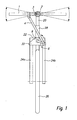
- FIG. 1 Fig. 3 is a schematic principle diagram of an embodiment of the present invention shown as a front view of a bicycle.
- the handlebar 1 is further attached via the pivot, which also includes a locking device 3, for example in the form of a bolt for decommissioning of the arm drive unit, to a handlebar fork, which includes a steerer 20, a cross member 22 attached to the steerer 20 and two forks 24a and 24b wherein the forks 24a and 24b are secured to the cross member 22 on a side opposite the steerer 20.
- the locking device 3 may also be omitted in a simpler or alternative embodiment.
- the steerer 20 is rotatably connected to a bicycle frame 28 and forms a steering head bearing 9, around which the handlebar 1 and the steering fork can be rotated.
- the handlebar 1 is connected via a connecting rod 4 articulated to a crank mechanism 6, which is fastened by means of a crank holder 30 to the two forks 24a and 24b and to the cross member 22. The tilting movement of the handlebar 1 is converted in this way into a rotational movement.
- FIG. 2 shows another schematic basic function image of the embodiment of the present invention FIG. 1 in side view.
- FIG. 3 will be in FIG. 2 shown details of the arm drive unit even more clearly visible.
- the rotational movement is transmitted either directly or via a gear 5 with a connecting shaft 29 to a shaft joint 8, which is mounted under the steering head bearing 9 and transmits the rotational movement to a frame-fixed component.
- a transmission of the rotational movement is realized by the crank mechanism 6 via a universal joint as a shaft joint 8, which is mounted directly under the lower steering head bearing 9.
- the shaft joint 8 in addition to the transmission of the rotary motion has the task to allow a steering movement of the steering fork of up to 90 ° in both directions, ie the steering movement can be up to 90 ° to the right and left. This ensures the steerability of the bicycle.
- the rotational movement is introduced into a trained as a bevel gear deflection 11, for example, which is attached to the frame with the bracket 10 and the rotational movement deflects by 90 °.
- a sprocket 13 or a toothed belt is mounted directly or via a clutch with which the rotational movement is transmitted via a chain 14 or a timing belt directly to another sprocket 15 and a timing belt on a drive shaft 31 of the leg drive.
- a firm connection between arm and leg drive is made, which allows a synchronous movement.
- the conventional circuit for changing the gear ratios thus affects the arm and leg drive alike. For the arm drive therefore no separate circuit must be provided.
- the transmission 5 can be installed with a correspondingly designed translation between the crank mechanism 6 and the connecting shaft 29.
- a different length of the arm of the crank mechanism 6 can be selected to specify the force required when operating the handlebar 1.
- this can also be associated with a greater deflection of the handlebar 1.
- the attachment of the deflection gear 11 is mounted on a sliding bracket 10. This allows chain 14 or Timing belts are tensioned.
- the holder 30 of the crank mechanism 6 can be slidably mounted in height to align the shaft joint 8 can.
- crank mechanism 6 can also be driven by the movement of a parallelogram system on the handlebar 1, which is not shown in the figures.
- the handlebar stems are moved up and down in parallel and do not cause any tilting movement.
- the implementation of such a parallelogram system is known to a person skilled in the art.
- the invention can be integrated into existing bicycle concepts with little modification to the fork without requiring major changes to the bicycle frame and standard components such as drive elements, circuitry and brake.
- the handlebar 1 can be adjusted in height.
- the handlebar stem (with rotatably mounted Lenkstangel) can be moved as in a conventional bicycle on the steering tube or the steerer tube 20 of the fork up / down. In this case, only the length of the connecting rod 4, which acts on the crank mechanism 6, to be adjusted in length.
- the adjustment of the distance between handlebar and saddle can be made possible as with a conventional bicycle on the installation of different length handlebar stems.
- the rotary motion is deflected by a deflection gear by 90 ° and the movement is over
- a chain to transfer the sprocket to another sprocket connected to the drive shaft of the leg drive (either on the right or left side).
- a toothed belt drive can be used instead of the sprockets and the chain. It can also be a transmission with gears on the output shaft directly or with intermediate wheels on the drive shaft of the leg drive.
- the bevel gear is not integrated directly into the drive shaft of the leg drive.
Landscapes
- Engineering & Computer Science (AREA)
- Chemical & Material Sciences (AREA)
- Combustion & Propulsion (AREA)
- Transportation (AREA)
- Mechanical Engineering (AREA)
- Steering Devices For Bicycles And Motorcycles (AREA)
Applications Claiming Priority (1)
| Application Number | Priority Date | Filing Date | Title |
|---|---|---|---|
| DE200810021253 DE102008021253A1 (de) | 2008-04-29 | 2008-04-29 | Fahrrad mit Armantrieb |
Publications (2)
| Publication Number | Publication Date |
|---|---|
| EP2113455A1 true EP2113455A1 (fr) | 2009-11-04 |
| EP2113455B1 EP2113455B1 (fr) | 2012-10-31 |
Family
ID=40929663
Family Applications (1)
| Application Number | Title | Priority Date | Filing Date |
|---|---|---|---|
| EP20090003096 Active EP2113455B1 (fr) | 2008-04-29 | 2009-03-04 | Vélo doté d'un entraînement de bras |
Country Status (2)
| Country | Link |
|---|---|
| EP (1) | EP2113455B1 (fr) |
| DE (1) | DE102008021253A1 (fr) |
Cited By (1)
| Publication number | Priority date | Publication date | Assignee | Title |
|---|---|---|---|---|
| CN103332257A (zh) * | 2013-07-22 | 2013-10-02 | 黄东子 | 仿生人力智能驱动装置 |
Families Citing this family (1)
| Publication number | Priority date | Publication date | Assignee | Title |
|---|---|---|---|---|
| DE102019005388B4 (de) | 2019-07-30 | 2021-09-09 | Christoph Tischer | Antriebseinheit für Fahrräder und Fitnessgeräte |
Citations (7)
| Publication number | Priority date | Publication date | Assignee | Title |
|---|---|---|---|---|
| US690180A (en) * | 1901-03-18 | 1901-12-31 | Frode H Pierson | Bicycle. |
| FR596442A (fr) * | 1925-04-07 | 1925-10-23 | Dispositif pour la commande simultanée des bicyclettes par les pédales et le guidon | |
| FR783793A (fr) * | 1934-03-28 | 1935-07-18 | Bicyclette à propulsion mixte, par les jambes et par les bras | |
| FR869538A (fr) | 1940-03-05 | 1942-02-04 | Perfectionnements aux bicyclettes et autres véhicules à pédales comportant un mécanisme de propulsion supplémentaire à bras | |
| FR939834A (fr) * | 1947-01-20 | 1948-11-25 | Dispositif perfectionné de transmission de mouvement pour bicyclettes et engins analogues | |
| FR2669600A1 (fr) | 1990-11-23 | 1992-05-29 | Gregoire Cyril | Bicyclette propulsee par l'energie musculaire des bras et des jambes. |
| WO2006132450A1 (fr) | 2005-06-08 | 2006-12-14 | Kie-Ho Cynn | Bicyclette mue par la force des bras et des jambes |
-
2008
- 2008-04-29 DE DE200810021253 patent/DE102008021253A1/de not_active Withdrawn
-
2009
- 2009-03-04 EP EP20090003096 patent/EP2113455B1/fr active Active
Patent Citations (7)
| Publication number | Priority date | Publication date | Assignee | Title |
|---|---|---|---|---|
| US690180A (en) * | 1901-03-18 | 1901-12-31 | Frode H Pierson | Bicycle. |
| FR596442A (fr) * | 1925-04-07 | 1925-10-23 | Dispositif pour la commande simultanée des bicyclettes par les pédales et le guidon | |
| FR783793A (fr) * | 1934-03-28 | 1935-07-18 | Bicyclette à propulsion mixte, par les jambes et par les bras | |
| FR869538A (fr) | 1940-03-05 | 1942-02-04 | Perfectionnements aux bicyclettes et autres véhicules à pédales comportant un mécanisme de propulsion supplémentaire à bras | |
| FR939834A (fr) * | 1947-01-20 | 1948-11-25 | Dispositif perfectionné de transmission de mouvement pour bicyclettes et engins analogues | |
| FR2669600A1 (fr) | 1990-11-23 | 1992-05-29 | Gregoire Cyril | Bicyclette propulsee par l'energie musculaire des bras et des jambes. |
| WO2006132450A1 (fr) | 2005-06-08 | 2006-12-14 | Kie-Ho Cynn | Bicyclette mue par la force des bras et des jambes |
Cited By (1)
| Publication number | Priority date | Publication date | Assignee | Title |
|---|---|---|---|---|
| CN103332257A (zh) * | 2013-07-22 | 2013-10-02 | 黄东子 | 仿生人力智能驱动装置 |
Also Published As
| Publication number | Publication date |
|---|---|
| EP2113455B1 (fr) | 2012-10-31 |
| DE102008021253A1 (de) | 2009-11-05 |
Similar Documents
| Publication | Publication Date | Title |
|---|---|---|
| EP2075183B1 (fr) | Tricycle pliable pour handicapé | |
| EP4229317B1 (fr) | Moyen de transport pouvant être entraîné simultanément de manière électromotrice et par la puissance musculaire humaine | |
| EP3036150B1 (fr) | Deux-roues avec bras oscillant muni d'un dispositif de propulsion | |
| DE69610054T2 (de) | Fahrrad mit zusätzlichem armantrieb | |
| DE19710697A1 (de) | Gefedertes Fahrrad | |
| DE69720711T2 (de) | Fahrrad mit zweiradantrieb | |
| EP2113455B1 (fr) | Vélo doté d'un entraînement de bras | |
| EP0010201A1 (fr) | Bicyclette | |
| DE102005058245A1 (de) | Fahrrad mit Frontantrieb | |
| DE102015015996B3 (de) | Liegefahrrad | |
| DE102005043423A1 (de) | Verstellbarer Sattelunterbau | |
| WO2001002240A1 (fr) | Bicyclette | |
| DE102019121133B4 (de) | Bewegungsvorrichtung für Personen | |
| EP0387382B1 (fr) | Dispositif de manivelle pour bicyclette, tricycle ou similaire | |
| EP2790997B1 (fr) | Trottinette à entraînement manuel | |
| DE202021105698U1 (de) | Lastenfahrrad | |
| DE102004033810B4 (de) | Fahrradtandem | |
| DE102004014559B3 (de) | Fahrrad mit einem Lenker und einer zusätzlichen armkraftbetätigten Antriebsvorrichtung | |
| DE3720364C2 (de) | Kurbelgetriebe fuer fahrraeder, dreiraeder oder dergl. | |
| DE8903620U1 (de) | Tretkurbel | |
| DE19961176C2 (de) | Eine mit den Händen zu bedienende, kombinierte Kraftübertragungs- und Lenkeinrichtung an einem Fahrrad oder Dreirad | |
| EP2665637A2 (fr) | Système de roue porteuse pour une bicyclette | |
| EP2596840A1 (fr) | waveboard avec direction | |
| EP2551177B1 (fr) | Tricyclette | |
| DE20009705U1 (de) | Fahrzeug mit Drehschemellenkung |
Legal Events
| Date | Code | Title | Description |
|---|---|---|---|
| PUAI | Public reference made under article 153(3) epc to a published international application that has entered the european phase |
Free format text: ORIGINAL CODE: 0009012 |
|
| AK | Designated contracting states |
Kind code of ref document: A1 Designated state(s): AT BE BG CH CY CZ DE DK EE ES FI FR GB GR HR HU IE IS IT LI LT LU LV MC MK MT NL NO PL PT RO SE SI SK TR |
|
| AX | Request for extension of the european patent |
Extension state: AL BA RS |
|
| 17P | Request for examination filed |
Effective date: 20091015 |
|
| AKX | Designation fees paid |
Designated state(s): AT BE BG CH CY CZ DE DK EE ES FI FR GB GR HR HU IE IS IT LI LT LU LV MC MK MT NL NO PL PT RO SE SI SK TR |
|
| 17Q | First examination report despatched |
Effective date: 20110203 |
|
| RIC1 | Information provided on ipc code assigned before grant |
Ipc: B62M 1/12 20060101AFI20120323BHEP |
|
| GRAP | Despatch of communication of intention to grant a patent |
Free format text: ORIGINAL CODE: EPIDOSNIGR1 |
|
| GRAS | Grant fee paid |
Free format text: ORIGINAL CODE: EPIDOSNIGR3 |
|
| GRAA | (expected) grant |
Free format text: ORIGINAL CODE: 0009210 |
|
| RAP1 | Party data changed (applicant data changed or rights of an application transferred) |
Owner name: BERGER, JOACHIM |
|
| RIN1 | Information on inventor provided before grant (corrected) |
Inventor name: BERGER, JOACHIM |
|
| AK | Designated contracting states |
Kind code of ref document: B1 Designated state(s): AT BE BG CH CY CZ DE DK EE ES FI FR GB GR HR HU IE IS IT LI LT LU LV MC MK MT NL NO PL PT RO SE SI SK TR |
|
| REG | Reference to a national code |
Ref country code: GB Ref legal event code: FG4D Free format text: NOT ENGLISH Ref country code: CH Ref legal event code: PCOW Free format text: JOACHIM BERGER;BURGHALDENSTRASSE 23;71336 WAIBLINGEN (DE) Ref country code: CH Ref legal event code: NV Representative=s name: TROESCH SCHEIDEGGER WERNER AG Ref country code: CH Ref legal event code: EP |
|
| REG | Reference to a national code |
Ref country code: AT Ref legal event code: REF Ref document number: 581836 Country of ref document: AT Kind code of ref document: T Effective date: 20121115 |
|
| REG | Reference to a national code |
Ref country code: IE Ref legal event code: FG4D Free format text: LANGUAGE OF EP DOCUMENT: GERMAN |
|
| REG | Reference to a national code |
Ref country code: DE Ref legal event code: R096 Ref document number: 502009005215 Country of ref document: DE Effective date: 20121227 |
|
| REG | Reference to a national code |
Ref country code: NL Ref legal event code: T3 |
|
| REG | Reference to a national code |
Ref country code: LT Ref legal event code: MG4D |
|
| PG25 | Lapsed in a contracting state [announced via postgrant information from national office to epo] |
Ref country code: SE Free format text: LAPSE BECAUSE OF FAILURE TO SUBMIT A TRANSLATION OF THE DESCRIPTION OR TO PAY THE FEE WITHIN THE PRESCRIBED TIME-LIMIT Effective date: 20121031 Ref country code: FI Free format text: LAPSE BECAUSE OF FAILURE TO SUBMIT A TRANSLATION OF THE DESCRIPTION OR TO PAY THE FEE WITHIN THE PRESCRIBED TIME-LIMIT Effective date: 20121031 Ref country code: NO Free format text: LAPSE BECAUSE OF FAILURE TO SUBMIT A TRANSLATION OF THE DESCRIPTION OR TO PAY THE FEE WITHIN THE PRESCRIBED TIME-LIMIT Effective date: 20130131 Ref country code: IS Free format text: LAPSE BECAUSE OF FAILURE TO SUBMIT A TRANSLATION OF THE DESCRIPTION OR TO PAY THE FEE WITHIN THE PRESCRIBED TIME-LIMIT Effective date: 20130228 Ref country code: HR Free format text: LAPSE BECAUSE OF FAILURE TO SUBMIT A TRANSLATION OF THE DESCRIPTION OR TO PAY THE FEE WITHIN THE PRESCRIBED TIME-LIMIT Effective date: 20121031 Ref country code: LT Free format text: LAPSE BECAUSE OF FAILURE TO SUBMIT A TRANSLATION OF THE DESCRIPTION OR TO PAY THE FEE WITHIN THE PRESCRIBED TIME-LIMIT Effective date: 20121031 Ref country code: ES Free format text: LAPSE BECAUSE OF FAILURE TO SUBMIT A TRANSLATION OF THE DESCRIPTION OR TO PAY THE FEE WITHIN THE PRESCRIBED TIME-LIMIT Effective date: 20130211 |
|
| PG25 | Lapsed in a contracting state [announced via postgrant information from national office to epo] |
Ref country code: LV Free format text: LAPSE BECAUSE OF FAILURE TO SUBMIT A TRANSLATION OF THE DESCRIPTION OR TO PAY THE FEE WITHIN THE PRESCRIBED TIME-LIMIT Effective date: 20121031 Ref country code: GR Free format text: LAPSE BECAUSE OF FAILURE TO SUBMIT A TRANSLATION OF THE DESCRIPTION OR TO PAY THE FEE WITHIN THE PRESCRIBED TIME-LIMIT Effective date: 20130201 Ref country code: PT Free format text: LAPSE BECAUSE OF FAILURE TO SUBMIT A TRANSLATION OF THE DESCRIPTION OR TO PAY THE FEE WITHIN THE PRESCRIBED TIME-LIMIT Effective date: 20130228 Ref country code: CY Free format text: LAPSE BECAUSE OF FAILURE TO SUBMIT A TRANSLATION OF THE DESCRIPTION OR TO PAY THE FEE WITHIN THE PRESCRIBED TIME-LIMIT Effective date: 20121031 Ref country code: PL Free format text: LAPSE BECAUSE OF FAILURE TO SUBMIT A TRANSLATION OF THE DESCRIPTION OR TO PAY THE FEE WITHIN THE PRESCRIBED TIME-LIMIT Effective date: 20121031 Ref country code: SI Free format text: LAPSE BECAUSE OF FAILURE TO SUBMIT A TRANSLATION OF THE DESCRIPTION OR TO PAY THE FEE WITHIN THE PRESCRIBED TIME-LIMIT Effective date: 20121031 |
|
| PG25 | Lapsed in a contracting state [announced via postgrant information from national office to epo] |
Ref country code: EE Free format text: LAPSE BECAUSE OF FAILURE TO SUBMIT A TRANSLATION OF THE DESCRIPTION OR TO PAY THE FEE WITHIN THE PRESCRIBED TIME-LIMIT Effective date: 20121031 Ref country code: CZ Free format text: LAPSE BECAUSE OF FAILURE TO SUBMIT A TRANSLATION OF THE DESCRIPTION OR TO PAY THE FEE WITHIN THE PRESCRIBED TIME-LIMIT Effective date: 20121031 Ref country code: BG Free format text: LAPSE BECAUSE OF FAILURE TO SUBMIT A TRANSLATION OF THE DESCRIPTION OR TO PAY THE FEE WITHIN THE PRESCRIBED TIME-LIMIT Effective date: 20130131 Ref country code: DK Free format text: LAPSE BECAUSE OF FAILURE TO SUBMIT A TRANSLATION OF THE DESCRIPTION OR TO PAY THE FEE WITHIN THE PRESCRIBED TIME-LIMIT Effective date: 20121031 Ref country code: SK Free format text: LAPSE BECAUSE OF FAILURE TO SUBMIT A TRANSLATION OF THE DESCRIPTION OR TO PAY THE FEE WITHIN THE PRESCRIBED TIME-LIMIT Effective date: 20121031 |
|
| PG25 | Lapsed in a contracting state [announced via postgrant information from national office to epo] |
Ref country code: RO Free format text: LAPSE BECAUSE OF FAILURE TO SUBMIT A TRANSLATION OF THE DESCRIPTION OR TO PAY THE FEE WITHIN THE PRESCRIBED TIME-LIMIT Effective date: 20121031 Ref country code: IT Free format text: LAPSE BECAUSE OF FAILURE TO SUBMIT A TRANSLATION OF THE DESCRIPTION OR TO PAY THE FEE WITHIN THE PRESCRIBED TIME-LIMIT Effective date: 20121031 |
|
| PLBE | No opposition filed within time limit |
Free format text: ORIGINAL CODE: 0009261 |
|
| STAA | Information on the status of an ep patent application or granted ep patent |
Free format text: STATUS: NO OPPOSITION FILED WITHIN TIME LIMIT |
|
| BERE | Be: lapsed |
Owner name: BERGER, JOACHIM Effective date: 20130331 |
|
| 26N | No opposition filed |
Effective date: 20130801 |
|
| PG25 | Lapsed in a contracting state [announced via postgrant information from national office to epo] |
Ref country code: MC Free format text: LAPSE BECAUSE OF NON-PAYMENT OF DUE FEES Effective date: 20130331 |
|
| GBPC | Gb: european patent ceased through non-payment of renewal fee |
Effective date: 20130304 |
|
| REG | Reference to a national code |
Ref country code: DE Ref legal event code: R097 Ref document number: 502009005215 Country of ref document: DE Effective date: 20130801 |
|
| REG | Reference to a national code |
Ref country code: IE Ref legal event code: MM4A |
|
| PG25 | Lapsed in a contracting state [announced via postgrant information from national office to epo] |
Ref country code: IE Free format text: LAPSE BECAUSE OF NON-PAYMENT OF DUE FEES Effective date: 20130304 Ref country code: BE Free format text: LAPSE BECAUSE OF NON-PAYMENT OF DUE FEES Effective date: 20130331 Ref country code: GB Free format text: LAPSE BECAUSE OF NON-PAYMENT OF DUE FEES Effective date: 20130304 |
|
| PGFP | Annual fee paid to national office [announced via postgrant information from national office to epo] |
Ref country code: CH Payment date: 20140326 Year of fee payment: 6 |
|
| PGFP | Annual fee paid to national office [announced via postgrant information from national office to epo] |
Ref country code: FR Payment date: 20140319 Year of fee payment: 6 |
|
| PG25 | Lapsed in a contracting state [announced via postgrant information from national office to epo] |
Ref country code: MT Free format text: LAPSE BECAUSE OF FAILURE TO SUBMIT A TRANSLATION OF THE DESCRIPTION OR TO PAY THE FEE WITHIN THE PRESCRIBED TIME-LIMIT Effective date: 20121031 |
|
| PG25 | Lapsed in a contracting state [announced via postgrant information from national office to epo] |
Ref country code: TR Free format text: LAPSE BECAUSE OF FAILURE TO SUBMIT A TRANSLATION OF THE DESCRIPTION OR TO PAY THE FEE WITHIN THE PRESCRIBED TIME-LIMIT Effective date: 20121031 |
|
| PG25 | Lapsed in a contracting state [announced via postgrant information from national office to epo] |
Ref country code: LU Free format text: LAPSE BECAUSE OF NON-PAYMENT OF DUE FEES Effective date: 20130304 Ref country code: HU Free format text: LAPSE BECAUSE OF FAILURE TO SUBMIT A TRANSLATION OF THE DESCRIPTION OR TO PAY THE FEE WITHIN THE PRESCRIBED TIME-LIMIT; INVALID AB INITIO Effective date: 20090304 Ref country code: MK Free format text: LAPSE BECAUSE OF FAILURE TO SUBMIT A TRANSLATION OF THE DESCRIPTION OR TO PAY THE FEE WITHIN THE PRESCRIBED TIME-LIMIT Effective date: 20121031 |
|
| REG | Reference to a national code |
Ref country code: CH Ref legal event code: PL |
|
| REG | Reference to a national code |
Ref country code: FR Ref legal event code: ST Effective date: 20151130 |
|
| PG25 | Lapsed in a contracting state [announced via postgrant information from national office to epo] |
Ref country code: LI Free format text: LAPSE BECAUSE OF NON-PAYMENT OF DUE FEES Effective date: 20150331 Ref country code: CH Free format text: LAPSE BECAUSE OF NON-PAYMENT OF DUE FEES Effective date: 20150331 |
|
| PG25 | Lapsed in a contracting state [announced via postgrant information from national office to epo] |
Ref country code: FR Free format text: LAPSE BECAUSE OF NON-PAYMENT OF DUE FEES Effective date: 20150331 |
|
| PGFP | Annual fee paid to national office [announced via postgrant information from national office to epo] |
Ref country code: NL Payment date: 20170323 Year of fee payment: 9 |
|
| PGFP | Annual fee paid to national office [announced via postgrant information from national office to epo] |
Ref country code: AT Payment date: 20170322 Year of fee payment: 9 |
|
| REG | Reference to a national code |
Ref country code: NL Ref legal event code: MM Effective date: 20180401 |
|
| REG | Reference to a national code |
Ref country code: AT Ref legal event code: MM01 Ref document number: 581836 Country of ref document: AT Kind code of ref document: T Effective date: 20180304 |
|
| PG25 | Lapsed in a contracting state [announced via postgrant information from national office to epo] |
Ref country code: NL Free format text: LAPSE BECAUSE OF NON-PAYMENT OF DUE FEES Effective date: 20180401 |
|
| PG25 | Lapsed in a contracting state [announced via postgrant information from national office to epo] |
Ref country code: AT Free format text: LAPSE BECAUSE OF NON-PAYMENT OF DUE FEES Effective date: 20180304 |
|
| PGFP | Annual fee paid to national office [announced via postgrant information from national office to epo] |
Ref country code: DE Payment date: 20250521 Year of fee payment: 17 |