EP2113620A1 - Tür- und/oder Fensterbeschlag - Google Patents
Tür- und/oder Fensterbeschlag Download PDFInfo
- Publication number
- EP2113620A1 EP2113620A1 EP09004878A EP09004878A EP2113620A1 EP 2113620 A1 EP2113620 A1 EP 2113620A1 EP 09004878 A EP09004878 A EP 09004878A EP 09004878 A EP09004878 A EP 09004878A EP 2113620 A1 EP2113620 A1 EP 2113620A1
- Authority
- EP
- European Patent Office
- Prior art keywords
- actuating shaft
- sleeve
- handle
- counter
- door
- Prior art date
- Legal status (The legal status is an assumption and is not a legal conclusion. Google has not performed a legal analysis and makes no representation as to the accuracy of the status listed.)
- Granted
Links
- 238000004146 energy storage Methods 0.000 description 4
- 239000000463 material Substances 0.000 description 3
- 238000007665 sagging Methods 0.000 description 3
- 238000003780 insertion Methods 0.000 description 2
- 230000037431 insertion Effects 0.000 description 2
- 238000004519 manufacturing process Methods 0.000 description 2
- 229920003023 plastic Polymers 0.000 description 2
- 239000004033 plastic Substances 0.000 description 2
- 229910001369 Brass Inorganic materials 0.000 description 1
- 229910000906 Bronze Inorganic materials 0.000 description 1
- 229910045601 alloy Inorganic materials 0.000 description 1
- 239000000956 alloy Substances 0.000 description 1
- 229910052782 aluminium Inorganic materials 0.000 description 1
- XAGFODPZIPBFFR-UHFFFAOYSA-N aluminium Chemical compound [Al] XAGFODPZIPBFFR-UHFFFAOYSA-N 0.000 description 1
- 239000010951 brass Substances 0.000 description 1
- 239000010974 bronze Substances 0.000 description 1
- 230000000295 complement effect Effects 0.000 description 1
- KUNSUQLRTQLHQQ-UHFFFAOYSA-N copper tin Chemical compound [Cu].[Sn] KUNSUQLRTQLHQQ-UHFFFAOYSA-N 0.000 description 1
- 230000007423 decrease Effects 0.000 description 1
- 238000006073 displacement reaction Methods 0.000 description 1
- 239000010970 precious metal Substances 0.000 description 1
- 229910001220 stainless steel Inorganic materials 0.000 description 1
Images

Classifications
-
- E—FIXED CONSTRUCTIONS
- E05—LOCKS; KEYS; WINDOW OR DOOR FITTINGS; SAFES
- E05B—LOCKS; ACCESSORIES THEREFOR; HANDCUFFS
- E05B3/00—Fastening knobs or handles to lock or latch parts
- E05B3/06—Fastening knobs or handles to lock or latch parts by means arranged in or on the rose or escutcheon
-
- E—FIXED CONSTRUCTIONS
- E05—LOCKS; KEYS; WINDOW OR DOOR FITTINGS; SAFES
- E05B—LOCKS; ACCESSORIES THEREFOR; HANDCUFFS
- E05B15/00—Other details of locks; Parts for engagement by bolts of fastening devices
- E05B15/0053—Other details of locks; Parts for engagement by bolts of fastening devices means providing a stable, i.e. indexed, position of lock parts
- E05B2015/0066—Other details of locks; Parts for engagement by bolts of fastening devices means providing a stable, i.e. indexed, position of lock parts axially operated
Definitions
- the invention relates to a door and / or window fitting, which has a shield with a Schildaus strictlyung, wherein in the SchildausNFung an actuating shaft is rotatably mounted, but axially immovable, wherein the actuating shaft emanates from a handle, and wherein the actuating shaft of a rotationally fixed to the shield arranged flange sleeve is surrounded, and wherein one of the flange sleeve associated counter sleeve is provided which is slidably mounted relative to the actuating shaft.
- the DE 33 20 193 C2 discloses a door fitting, consisting of a shield with a Schildaus brieflyung, and rotatable but axially non-displaceably mounted actuating shaft, with a subsequent to a free end handle, wherein the actuating shaft of a non-rotatably mounted on the shield, partially protruding into the Schildaus predominantlyung flange sleeve is surrounded, whose axis perpendicular to the axis of the actuating shaft flange between the shield and the handle is arranged, and facing the handle, in the circumferential direction having a bevel end face mounted axially displaceable in a handle recess and supported by a supported on the bottom coil spring in the direction of the shield applied control applied.
- the flange sleeve has a projecting into the handle recess guide collar with a wedge portion which on a complementary wedge portion of as a counter sleeve running control applied.
- the German utility model DE 203 09 658 improves the subject of the DE 33 20 193 C2 to the extent that the handle can be converted into several functional positions. For example, doors and / or windows can be transferred not only in an open position but also in a tilted position. Due to this beats the DE 203 09 658 to provide a guide collar with at least four Kragenaus traditions, wherein the counter-sleeve has at least four corresponding axial projections.
- the embodiment according to the DE 203 09 658 has proven itself in practice.
- the counter sleeve on its outer circumference on radial projections, which engage in corresponding axial grooves, which are introduced in an inner wall of the handle or in a wall of an overlapping portion of the handle.
- the radial projections are projecting from the counter sleeve, so that the handle, or the area of the handle engaging over the actuating shaft, must be designed with a correspondingly large diameter and a correspondingly large wall thickness in order to receive or guide the counter sleeve or its radial projections.
- the operating shaft cross-section of the handle so the overreaching portion is seen with its dimensions, especially in the radial direction, therefore directly coupled to the configuration of the projections or their radial projection so that a diameter of, for example, 30 mm currently can not be exceeded.
- the invention has the object to improve a door and / or window fitting of the type mentioned by simple means so that the handle with its operating shaft cross-section in its dimensions, especially in the radial direction, can be performed reduced, and This can be used, for example, in narrow window frames.
- the object is achieved by a door or window fitting with the features of claim 1, wherein at least one axial groove is arranged on the actuating shaft, and that the counter-sleeve has at least one projection which is arranged on an inner periphery of the counter-sleeve so that this in the axial groove of the actuating shaft engages, so that the counter sleeve is mounted on the actuating shaft axially displaceable but non-rotatable.
- the internal arrangement of the projection which can also be referred to as a guide nose, is advantageously achieved that the resulting outer diameter of the counter-sleeve can be reduced or reduced.
- the area of the handle which overlaps the actuating shaft that is to say the overlapping section, can be reduced in its dimensions, in particular in the radial direction.
- the stated values should not be limiting. Rather, it is within the meaning of the invention, the handle the respective application areas, e.g. adapt to narrow window frame, which is advantageously possible by means of the invention. This will be discussed in more detail below.
- the invention is based on the finding that the area of the handle which overlaps the actuating shaft has, inter alia, the function of receiving and guiding the counter sleeve.
- the area of the handle that overlaps the actuating shaft had to be dimensioned sufficiently strong in its wall thickness in such a way that the axial grooves could be introduced for guiding the counter sleeve, while at the same time achieving a resistance against acting forces (for example rotational force, torsional force).
- the guide function of the handle is dispensed with, since the counter sleeve is now axially displaceably but non-rotatably guided on the actuating shaft.
- the operating shaft cross-section of the handle can therefore be performed with very small outside diameters under certain circumstances.
- the handle could be made cylindrical throughout, which of course should not be limiting.
- Another advantage is the material savings and the conservation of resources: door and / or window fittings or their visible components such as just as the handle, for example, from precious metals, stainless steels or other alloys such as brass or bronze or even Made of aluminum or plastics.
- the choice of materials should not be limited to the examples mentioned. Since the diameter of the handle, or of the operating shaft cross-section of the handle but can be made smaller in diameter and with a very low, but sufficiently resistant wall thickness, significant material savings are achieved here, which directly to the manufacturing cost but also to the lower impacted resources.
- the inventive solution is advantageous because the handle can be made easier without attention to tolerances of the previously introduced into the handle Axialnuten, because the counter sleeve is axially slidably guided by the actuating shaft but non-rotatably.
- a recess for receiving a force accumulator such as a spring is arranged.
- the spring rests on the one hand on a base of the recess and on the other hand on the counter sleeve, so that it is axially displaceable due to spring force.
- the axial groove is introduced in its longitudinal extent from a free end of the actuating shaft in the direction of the recess on the outside so in the actuating shaft that an abutment shoulder is formed to the recess, which can be regarded as a movement limitation of the counter sleeve in the axial direction.
- the door or window fitting according to the invention can be arranged as a door handle, knob or window handle on rosettes, long or short shields.
- the solution provided by the invention is to be regarded as advantageous in that window frames are made increasingly narrow, so that the window handle can be correspondingly adapted in terms of its dimensions, in particular in the overlapping section.
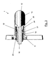
- FIG. 1 shows an example of a door fitting 1.
- the door fitting 1 has a shield 2 with a Schildausappelung 3.
- the SchildausANSung 3 has a circular cross-section with two diametrically opposed recesses or axial grooves 4.
- more than two axial grooves 4 seen in the circumferential direction of the recess 3 can be provided evenly distributed.
- a flange 6 is used in the Schildaus adoptedung 3.
- the flange sleeve 6 has an insertion region 7 adapted to the blade recess 3 and a abutment flange 8.
- the insertion region 7 is cylindrical, wherein on its outer periphery to the axial grooves 4 corresponding webs 9 are arranged.
- the flange 6 With the abutment flange 8, the flange 6 is in the assembled state of the shield 2, wherein the flange sleeve 6 by means of the axial grooves 4 and the webs 9 rotatably disposed on the plate 2, and rotatably inserted in the Schildausappelung 3.
- the flange sleeve 6 has a guide collar 11, the collar recesses 12 has. In the illustrated embodiment, four Kragenaus traditions 12 are provided.
- the flange 6 can also be referred to as a detent plate.
- the door fitting 1 also has a handle 13.
- the handle 13 is executed in the illustrated embodiment as a door handle.
- From the handle 13 is an actuating shaft 14, which is at least partially overlapped by an overlapping portion 15 of the handle 13.
- a square opening for receiving a square 16 is arranged on the inside ( FIG. 3 ).
- the actuating shaft 14 is executed in the illustrated embodiment with a round outer circumferential. In the region of a free end 17 of the actuating shaft 14, an annular groove 18 is introduced.
- the actuating shaft 14 has at least one outwardly disposed axial groove 19 which is guided from the free end 17 in the direction of the overlapping portion 15 in this.
- the handle 13 with the actuating shaft 14 is preferably made in one piece, preferably cast, wherein the axial groove 19 is preferably molded with.
- the exemplary door handle 1 has a counter sleeve 21 corresponding to the flange sleeve 6.
- the counter sleeve 21 may also be referred to as a locking piston, and has to the KragenausEnglishept 12 of the flange 6 corresponding axial projections 22.
- the flange 6 and the counter sleeve 21 may be made of a plastic.
- the counter sleeve 21 has on its inner circumference at least one projection 23 which is designed to correspond to the axial groove 19 of the actuating shaft 14.
- the projection 23 may also be referred to as a guide nose and extends with its free end in the direction of a central axis X of the counter sleeve 21st
- two diametrically opposed axial grooves 19 are arranged outside of the actuating shaft 14, so cheaper Way also two corresponding projections 23 are provided on the counter-sleeve 21.
- the counter sleeve 21 is slidably mounted on the actuating shaft 14 in the axial direction, but non-rotatably.
- a recess 24 (FIG. FIG. 3 ), in which a force accumulator 26 can be inserted.
- the energy storage is exemplified as a helical spring.
- FIG. 3 an assembled state of the door fitting 1 is shown in a sectional view.
- the flange 6 is inserted in the Schildaus strictlyung 3.
- a securing means such as a snap ring 28, a U-plate 29 and a spring washer 31, preferably a corrugated spring washer for securing arranged.
- One of the securing means settles in the annular groove 18.
- the square 16 is received in the actuating shaft 14.
- the counter-sleeve 21 abuts with its axial projections 22 on the KragenausEnglishept 12 of the flange 6. Further, the counter sleeve 21 engages with their radially inwardly extending projections 23 in the respective outer axial groove 19 a.
- the energy accumulator 26 is inserted into the recess 24 and is located on the one hand at the bottom and on the other hand on the counter sleeve 21 at.
- FIG. 3 can be seen further, the respective axial groove 19 is guided into the overreaching portion 15 that a contact shoulder 32 is formed for the counter-sleeve 21.
- the abutment shoulder 32 limits an axial displacement of the counter-sleeve 21 into the overlapping section 15 in that the projections 23 of the counter-sleeve 21 can abut against it. But this is probably due to the relatively strong design of the energy storage 26 excluded.
- the energy storage 26 is designed so that an exact return of the counter sleeve 21 in their in FIG. 3 shown starting position is reached. In this respect, a sagging of the handle 13 and the door handle is prevented at the same time.
- the counter sleeve 21 Upon actuation of the handle 13, the counter sleeve 21 is displaced by cooperation of the Kragenaus Principle Heidelberg 12 with the axial projections 22 in the direction of the energy storage 26, which is compressed accordingly.
- the energy accumulator 26, together with the flange sleeve 6 and the counter sleeve 21 an exact return of the door handle to its normal position and prevents sagging.
- the handle 13 and its overlapping portion 15 can be executed with a cylindrical configuration seen in cross-section.
- the fact that the counter sleeve 21 is mounted and guided axially displaceably on the actuating shaft 14, the overreach portion 15 may be designed with a relatively small wall thickness, which only needs to be designed with respect to the expected forces acting.
- a short plate is exemplified as a shield 2.
- the shield 2 can also be designed as a long shield. It is also conceivable to attach a cover plate to the plate. It is also possible to provide a rosette instead of the sign.
- the handle 13 may be executed instead of the exemplary embodiment as a door handle as a button.
Landscapes
- Engineering & Computer Science (AREA)
- Mechanical Engineering (AREA)
- Lock And Its Accessories (AREA)
- Pivots And Pivotal Connections (AREA)
- Vehicle Interior And Exterior Ornaments, Soundproofing, And Insulation (AREA)
Abstract
Description
- Die Erfindung betrifft einen Tür- und/oder Fensterbeschlag, der ein Schild mit einer Schildausnehmung aufweist, wobei in der Schildausnehmung eine Betätigungswelle drehbar, aber axial unverschiebbar gelagert ist, wobei die Betätigungswelle von einer Handhabe ausgeht, und wobei die Betätigungswelle von einer drehfest am Schild angeordneten Flanschhülse umgeben ist, und wobei eine der Flanschhülse zugeordnete Gegenhülse vorgesehen ist, die relativ zur Betätigungswelle verschiebbar gelagert ist.
- Derartige Tür- oder Fensterbeschläge sind bekannt.
- Beispielsweise die
DE 33 20 193 C2 offenbart einen Türbeschlag, bestehend aus einem Schild mit einer Schildausnehmung, und aus einer darin drehbar, aber axial unverschiebbar gelagerten Betätigungswelle, mit einer an deren einem freien Ende anschließenden Handhabe, wobei die Betätigungswelle von einer unverdrehbar am Schild befestigten, teilweise in die Schildausnehmung hineinragenden Flanschhülse umgeben ist, deren zur Achse der Betätigungswelle senkrechter Flansch zwischen dem Schild sowie der Handhabe angeordnet ist, und an deren Handhabe zugewandten, in Umfangsrichtung eine Schräge aufweisende Stirnfläche ein axial verschiebbar in einer Handhabenausnehmung gelagertes und von einer an deren Boden abgestützten Schraubenfeder in Richtung des Schildes beaufschlagtes Steuerelement anliegt. Um zu erreichen, dass bei Nachlassen der Wirkung einer Schlossfeder eines zugeordneten Schlosses ein ungenaues Schließen und ein Durchhängen eines Drückers als Handhabe vermieden ist, wird vorgeschlagen, dass die Flanschhülse einen in die Handhabenausnehmung hineinragenden Führungskragen mit einem Keilabschnitt aufweist, der an einem komplementären Keilabschnitt eines als Gegenhülse ausgeführten Steuerelementes anliegt. - Das deutsche Gebrauchsmuster
DE 203 09 658 verbessert den Gegenstand derDE 33 20 193 C2 dahingehend, als die Handhabe in mehrere Funktionsstellungen überführbar ist. Beispielsweise können Türen und/oder Fenster nicht nur in eine Öffnungsstellung sondern auch in eine Kippstellung überführt werden. Von daher schlägt dieDE 203 09 658 vor, einen Führungskragen mit wenigstens vier Kragenausnehmungen zu versehen, wobei die Gegenhülse wenigstens vier korrespondierende Axialvorsprünge aufweist. - Die Ausgestaltung gemäß der
DE 203 09 658 hat sich in der Praxis bewährt. Allerdings weist die Gegenhülse an ihrem Außenumfang radiale Vorsprünge auf, welche in entsprechende Axialnuten, welche in einer Innenwand der Handhabe bzw. in einer Wand eines Übergreifabschnittes der Handhabe eingebracht sind, eingreifen. Die radialen Vorsprünge stehen von der Gegenhülse ab, so dass die Handhabe, bzw. der die Betätigungswelle übergreifende Bereich der Handhabe mit einem entsprechend großen Durchmesser und einer entsprechend großen Wanddicke ausgeführt sein muss, um die Gegenhülse bzw. deren Radialvorsprünge aufzunehmen bzw. zu führen. - Der die Betätigungswelle übergreifende Bereich der Handhabe, also der Übergreifabschnitt ist mit seinen Abmessungen, insbesondere in Radialrichtung gesehen, demnach unmittelbar an die Ausgestaltung der Vorsprünge bzw. deren radialen Überstand so gekoppelt, dass ein Durchmesser von beispielsweise 30 mm derzeit nicht unterschritten werden kann.
- Von daher liegt der Erfindung die Aufgabe zugrunde einen Tür- und/oder Fensterbeschlag der Eingangs genannten Art mit einfachen Mitteln so zu verbessern, dass die Handhabe mit ihrem die Betätigungswelle übergreifenden Bereich in seinen Abmessungen, insbesondere in Radialrichtung gesehen, verringert ausgeführt werden kann, und dadurch beispielsweise bei schmalen Fensterrahmen einsetzbar ist.
- Erfindungsgemäß wird die Aufgabe durch einen Tür- oder Fensterbeschlag mit den Merkmalen des Anspruchs 1 gelöst, wobei an der Betätigungswelle zumindest eine Axialnut angeordnet ist, und dass die Gegenhülse zumindest einen Vorsprung aufweist, der an einem Innenumfang der Gegenhülse so angeordnet ist, dass dieser in die Axialnut der Betätigungswelle eingreift, so dass die Gegenhülse auf der Betätigungswelle axial verschiebbar aber unverdrehbar gelagert ist.
- Durch die innen liegende Anordnung des Vorsprungs, der auch als Führungsnase bezeichnet werden kann, wird vorteilhaft erreicht, dass der resultierende Außendurchmesser der Gegenhülse verkleinert bzw. reduziert werden kann. Daraus folgt aber zwangsläufig, dass auch der die Betätigungswelle übergreifende Bereich der Handhabe, also der Übergreifabschnitt in seinen Abmessungen, insbesondere in Radialrichtung gesehen verringert ausgeführt werden kann.
- Beispielsweise wäre eine Durchmesserreduzierung von z.B. 16% bezogen auf einen im Stand der Technik üblichen Durchmesser von 30 mm erreichbar, so dass der die Betätigungswelle übergreifende Bereich z.B. einen Durchmesserbetrag von 25 mm aufweisen kann. Selbstverständlich sollen die genannten Werte nicht beschränkend sein. Vielmehr liegt es im Sinne der Erfindung, die Handhabe den jeweiligen Einsatzbereichen, z.B. an schmalen Fensterrahmen anzupassen, was mittels der Erfindung vorteilhaft möglich ist. Hierauf wird weiter unten näher eingegangen.
- Der Erfindung liegt die Erkenntnis zugrunde, dass der die Betätigungswelle übergreifende Bereich der Handhabe unter anderem die Funktion der Aufnahme und Führung der Gegenhülse zukam. Insofern musste der die Betätigungswelle übergreifende Bereich der Handhabe in seiner Wandstärke entsprechend so stark dimensioniert sein, dass die Axialnuten zur Führung der Gegenhülse eingebracht werden konnten, gleichzeitig aber eine gegen einwirkende Kräfte (z.B. Drehkraft, Torsionskraft) entsprechende Widerstandsfähigkeit erzielt wurde.
- Mittels der Erfindung dagegen, wird auf die Führungsfunktion der Handhabe verzichtet, da die Gegenhülse nunmehr an der Betätigungswelle axial verschiebbar aber unverdrehbar geführt ist. Der die Betätigungswelle übergreifende Bereich der Handhabe kann daher unter Umständen mit sehr kleinen Außendurchmessern ausgeführt sein. Beispielsweise könnte die Handhabe durchgängig zylindrisch ausgeführt sein, was natürlich nicht beschränkend sein soll.
- Ein weiterer Vorteil ist in der Materialersparnis sowie der Ressourcenschonung zu sehen: Tür- und/oder Fensterbeschläge bzw. deren sichtbare Komponenten wie eben z.B. die Handhabe können beispielsweise aus Edelmetallen, Edelstählen oder anderen Legierungen wie zum Beispiel Messing oder Bronze oder auch aus Aluminium oder Kunststoffen hergestellt sein. Selbstverständlich soll die Werkstoffauswahl nicht auf die genannten Beispiele beschränkt sein. Da der Durchmesser der Handhabe, bzw. des die Betätigungswelle übergreifenden Bereiches der Handhabe aber im Durchmesser kleiner und mit einer sehr geringen, aber hinreichend widerstandsfähigen Wandstärke ausgeführt werden kann, werden hier erhebliche Materialeinsparungen erreicht, welche sich direkt auf die Herstellungskosten aber auch auf die geringer belasteten Ressourcen auswirkt.
- Aber auch aus fertigungstechnischen Gesichtspunkten ist die erfindungemäße Lösung vorteilhaft, da die Handhabe ohne Beachtung von Toleranzen der bisher in die Handhabe eingebrachten Axialnuten einfacher gefertigt werden kann, denn die Gegenhülse ist von der Betätigungswelle axial verschiebbar aber unverdrehbar geführt.
- Mittels der zumindest einen Axialnut und dem korrespondierenden Vorsprung der Gegenhülse ist diese hinreichend sicher in axialer Richtung verschiebbar aber unverdrehbar an der Betätigungswelle gelagert. Es liegt durchaus im Sinne der Erfindung, mehr als eine Axialnut außen an der Betätigungswelle anzuordnen bzw. einzubringen, weswegen auch mehrere, jeweils korrespondierende Vorsprünge an der Gegenhülse vorgesehen werden können. In bevorzugter Ausgestaltung sind zwei in Umfangsrichtung diametral gegenüberliegende Axialnuten außen an der Betätigungswelle angeordnet, weswegen auch die Gegenhülse zwei diametral zu einer Mittelachse angeordnete, zu den Axialnuten korrespondierende Vorsprünge aufweist.
- In der Handhabe ist eine Ausnehmung zur Aufnahme eines Kraftspeichers, wie zum Beispiel einer Feder angeordnet. Im montierten Zustand liegt die Feder einerseits an einem Grund der Ausnehmung und andererseits an der Gegenhülse an, so dass diese federkraftbedingt axial verschiebbar ist. Günstiger weise ist vorgesehen, dass die Axialnut in ihrer Längserstreckung von einem freien Ende der Betätigungswelle in Richtung zur Ausnehmung außen so in der Betätigungswelle eingebracht ist, dass eine Anlageschulter zur Ausnehmung gebildet ist, welche als Bewegungsbegrenzung der Gegenhülse in axialer Richtung angesehen werden kann.
- Der erfindungsgemäße Tür- oder Fensterbeschlag kann als Türdrücker, Knopf oder Fenstergriff auf Rosetten, Lang- oder Kurzschilden angeordnet werden. Insbesondere bei einem Fenster ist die mit der Erfindung zur Verfügung gestellte Lösung dahingehend als vorteilhaft anzusehen, als Fensterrahmen zunehmend schmaler ausgeführt werden, so dass der Fenstergriff in seinen Abmessungen, insbesondere im Übergreifabschnitt entsprechend anpassbar ist.
- Weitere vorteilhafte Ausgestaltungen der Erfindung sind in den Unteransprüchen sowie in der folgenden Figurenbeschreibung offenbart. Es zeigen:
- Fig. 1
- einen Türbeschlag in einer Explosionsdarstellung,
- Fig. 2
- den Türbeschlag aus
Figur 1 mit einzelnen Komponenten, und - Fig. 3
- den Türbeschlag aus
Figur 1 im montierten Zustand. - In den unterschiedlichen Figuren sind gleiche Teile stets mit denselben Bezugszeichen versehen, so dass diese in der Regel auch nur einmal beschrieben werden.
-
Figur 1 zeigt beispielhaft einen Türbeschlag 1. Der Türbeschlag 1 weist ein Schild 2 mit einer Schildausnehmung 3 auf. Die Schildausnehmung 3 hat einen kreisförmigen Querschnitt mit zwei diametral gegenüberliegenden Ausnehmungen bzw. Axialnuten 4. Natürlich können auch mehr als zwei Axialnuten 4 in Unfangsrichtung der Ausnehmung 3 gesehen gleich verteilt vorgesehen sein. - In die Schildausnehmung 3 ist eine Flanschhülse 6 einsetzbar. Die Flanschhülse 6 weist einen an die Schildausnehmung 3 angepassten Einsetzbereich 7 und einen Anlageflansch 8 auf. Der Einsetzbereich 7 ist zylindrisch ausgeführt, wobei an seinem Außenumfang zu den Axialnuten 4 korrespondierende Stege 9 angeordnet sind. Mit dem Anlageflansch 8 liegt die Flanschhülse 6 im montierten Zustand an dem Schild 2 an, wobei die Flanschhülse 6 mittels der Axialnuten 4 und den Stegen 9 drehfest an dem Schild 2 angeordnet, bzw. drehfest in der Schildausnehmung 3 eingesetzt ist.
- Die Flanschhülse 6 weist einen Führungskragen 11 auf, der Kragenausnehmungen 12 hat. In dem dargestellten Ausführungsbeispiel sind vier Kragenausnehmungen 12 vorgesehen. Die Flanschhülse 6 kann auch als Rastplatte bezeichnet werden.
- Der Türbeschlag 1 weist ferner eine Handhabe 13 auf. Die Handhabe 13 ist in dem dargestellten Ausführungsbeispiel als Türdrücker ausgeführt. Von der Handhabe 13 geht eine Betätigungswelle 14 aus, die zumindest bereichsweise von einem Übergreifabschnitt 15 der Handhabe 13 übergriffen wird. In der Betätigungswelle 14 ist innenseitig eine Vierkantöffnung zur Aufnahme eines Vierkants 16 angeordnet (
Figur 3 ). Die Betätigungswelle 14 ist im dargestellten Ausführungsbeispiel mit einem runden Außenumgang ausgeführt. Im Bereich eines freien Endes 17 der Betätigungswelle 14 ist eine Ringnut 18 eingebracht. - Wie der
Figur 1 zu entnehmen ist, weist die Betätigungswelle 14 zumindest eine außen angeordnete Axialnut 19 auf, welche von dem freien Ende 17 in Richtung zum Übergreifabschnitt 15 in diesen hineingeführt ist. Die Handhabe 13 mit der Betätigungswelle 14 ist bevorzugt einstückig hergestellt, vorzugsweise gegossen, wobei die Axialnut 19 vorzugsweise mit eingegossen wird. - Ferner weist der beispielhafte Türdrücker 1 eine zur Flanschhülse 6 korrespondierende Gegenhülse 21 auf. Die Gegenhülse 21 kann auch als Rastkolben bezeichnet werden, und weist zu den Kragenausnehmungen 12 der Flanschhülse 6 korrespondierende Axialvorsprünge 22 auf. Die Flanschhülse 6 und die Gegenhülse 21 können aus einem Kunststoff gefertigt sein.
- Die Gegenhülse 21 hat an ihrem Innenumfang zumindest einen Vorsprung 23, welcher zur Axialnut 19 der Betätigungswelle 14 korrespondierend ausgeführt ist. Der Vorsprung 23 kann auch als Führungsnase bezeichnet werden und erstreckt sich mit seinem freien Ende in Richtung zu einer Mittelachse X der Gegenhülse 21.
- In dem dargestellten Ausführungsbeispiel sind außen an der Betätigungswelle 14 zwei diametral gegenüberliegende Axialnuten 19 angeordnet, weswegen günstiger Weise auch zwei dazu korrespondierende Vorsprünge 23 an der Gegenhülse 21 vorgesehen sind.
- Mittels der Axialnut bzw. der Axialnuten 19 und der korrespondierenden Vorsprünge 23 ist die Gegenhülse 21 auf der Betätigungswelle 14 in Axialrichtung verschiebbar, aber unverdrehbar gelagert.
- Innerhalb der Handhabe 13 bzw. deren Übergreifabschnitt 15 ist eine Ausnehmung 24 (
Figur 3 ) eingebracht, in der ein Kraftspeicher 26 einsetzbar ist. Der Kraftspeicher ist beispielhaft als Schraubenfeder ausgeführt. - In
Figur 3 ist ein montierter Zustand des Türbeschlages 1 in einer Schnittdarstellung gezeigt. Die Flanschhülse 6 ist in der Schildausnehmung 3 eingesetzt. Die Betätigungswelle 14 durchgreift mit ihrem freien Ende 17 die Schildausnehmung 3 bzw. die Flanschhülse 6. Gegenüberliegend zu einer Sichtseite 27 ist gegebenenfalls ein Sicherungsmittel wie zum Beispiel ein Sprengring 28, eine U-Scheibe 29 und eine Federscheibe 31, bevorzugt eine gewellte Federscheibe zur Sicherung angeordnet. Eines der Sicherungsmittel legt sich in die Ringnut 18 ein. Der Vierkant 16 ist in der Betätigungswelle 14 aufgenommen. - Die Gegenhülse 21 liegt mit ihren Axialvorsprüngen 22 an den Kragenausnehmungen 12 der Flanschhülse 6 an. Ferner greift die Gegenhülse 21 mit ihren sich radial nach innen erstreckenden Vorsprüngen 23 in die jeweilige außen angeordnete Axialnut 19 ein. Der Kraftspeicher 26 ist in die Ausnehmung 24 eingesetzt und liegt einerseits an deren Grund und andererseits an der Gegenhülse 21 an.
- Wie der
Figur 3 weiter zu entnehmen ist, ist die jeweilige Axialnut 19 so in den Übergreifabschnitt 15 hineingeführt, dass eine Anlageschulter 32 für die Gegenhülse 21 gebildet ist. Die Anlageschulter 32 begrenzt eine axiale Verschiebung der Gegenhülse 21 in den Übergreifabschnitt 15, indem die Vorsprünge 23 der Gegenhülse 21 daran anschlagen können. Dies ist aber wohl aufgrund der relativ starken Ausgestaltung des Kraftspeichers 26 ausgeschlossen. Der Kraftspeicher 26 ist so ausgelegt, dass eine exakte Rückführung der Gegenhülse 21 in ihre inFigur 3 dargestellte Ausgangslage erreichbar ist. Insofern wird gleichzeitig ein Durchhängen der Handhabe 13 bzw. des Türdrückers verhindert. - Bei einem Betätigen der Handhabe 13 wird die Gegenhülse 21 durch zusammenwirken der Kragenausnehmungen 12 mit den Axialvorsprüngen 22 in Richtung zum Kraftspeicher 26 verschoben, welcher entsprechend zusammengedrückt wird. Der Kraftspeicher 26 bewirkt zusammen mit der Flanschhülse 6 und der Gegenhülse 21 eine exakte Rückführung des Türdrückers in seine Grundstellung und verhindert ein Durchhängen.
- Wie beispielsweise
Figur 3 entnehmbar ist, kann die Handhabe 13 bzw. ihr Übergreifabschnitt 15 mit im Querschnitt gesehen zylindrischer Ausgestaltung ausgeführt werden. Dadurch, dass die Gegenhülse 21 auf der Betätigungswelle 14 axial verschiebbar gelagert und geführt ist, kann der Übergreifabschnitt 15 mit einer relativ geringen Wandstärke ausgeführt sein, welche nur noch bezüglich der zu erwartenden einwirkenden Kräfte ausgelegt werden muss. - In dem dargestellten Ausführungsbeispiel ist als Schild 2 beispielhaft ein Kurzschild dargestellt. Natürlich kann das Schild 2 auch als Langschild ausgeführt sein. Denkbar ist auch eine Abdeckplatte an dem Schild zu befestigen. Möglich ist auch anstelle des Schildes eine Rosette vorzusehen. Selbstverständlich kann die Handhabe 13 anstelle der beispielhaften Ausgestaltung als Türdrücker auch als Knopf ausgeführt sein. Obwohl ein Türbeschlag beschrieben ist, können auch Fensterbeschläge erfindungsgemäß ausgeführt sein.
Claims (4)
- Tür- und/oder Fensterbeschlag, der ein Schild (2) mit einer Schildausnehmung (3) aufweist, wobei in der Schildausnehmung (3) eine Betätigungswelle (14) drehbar, aber axial unverschiebbar gelagert ist, wobei die Betätigungswelle (14) von einer Handhabe (13) ausgeht, und wobei die Betätigungswelle (14) von einer drehfest am Schild (2) angeordneten Flanschhülse (6) umgeben ist, und wobei eine der Flanschhülse (6) zugeordnete Gegenhülse (21) vorgesehen ist, die relativ zur Betätigungswelle (14) verschiebbar gelagert ist, dadurch gekennzeichnet, dass an der Betätigungswelle (14) zumindest eine Axialnut (19) angeordnet ist, und dass die Gegenhülse (21) zumindest einen Vorsprung (23) aufweist, der an einem Innenumfang der Gegenhülse (21) so angeordnet ist, dass dieser in die Axialnut (19) der Betätigungswelle (14) eingreift, so dass die Gegenhülse (21) auf der Betätigungswelle (14) axial verschiebbar aber unverdrehbar gelagert ist.
- Tür- oder Fensterbeschlag nach Anspruch 1, dadurch gekennzeichnet, dass an der Betätigungswelle (14) mehrere Axialnuten (19) angeordnet sind, und dass in der Gegenhülse (21) dazu korrespondierend mehrere Vorsprünge (23) angeordnet sind.
- Tür- oder Fensterbeschlag nach Anspruch 1 oder 2, dadurch gekennzeichnet, dass die zumindest eine Axialnut (19) von einem freien Ende (17) der Betätigungswelle (14) in Richtung zu einem Übergreifabschnitt (15) der Handhabe (13) in den Übergreifabschnitt (15) hineingeführt ist.
- Tür- oder Fensterbeschlag nach einem der vorhergehenden Ansprüche, dadurch gekennzeichnet, dass in der Handhabe (13) eine Ausnehmung (24) für einen Kraftspeicher (26) angeordnet ist, und dass die zumindest eine Axialnut (19) so in die Betätigungswelle (14) eingebracht ist, das eine Anlageschulter (32) gebildet ist.
Applications Claiming Priority (1)
| Application Number | Priority Date | Filing Date | Title |
|---|---|---|---|
| DE102008021760A DE102008021760B3 (de) | 2008-04-30 | 2008-04-30 | Tür- und/oder Fensterbeschlag |
Publications (2)
| Publication Number | Publication Date |
|---|---|
| EP2113620A1 true EP2113620A1 (de) | 2009-11-04 |
| EP2113620B1 EP2113620B1 (de) | 2010-04-28 |
Family
ID=40384753
Family Applications (1)
| Application Number | Title | Priority Date | Filing Date |
|---|---|---|---|
| EP09004878A Active EP2113620B1 (de) | 2008-04-30 | 2009-04-02 | Tür- und/oder Fensterbeschlag |
Country Status (3)
| Country | Link |
|---|---|
| EP (1) | EP2113620B1 (de) |
| AT (1) | ATE466154T1 (de) |
| DE (2) | DE102008021760B3 (de) |
Families Citing this family (1)
| Publication number | Priority date | Publication date | Assignee | Title |
|---|---|---|---|---|
| AU2012208994B2 (en) * | 2011-08-08 | 2016-02-25 | Azuma Design Pty Limited | A handle assembly |
Citations (4)
| Publication number | Priority date | Publication date | Assignee | Title |
|---|---|---|---|---|
| DE3320061A1 (de) * | 1983-06-03 | 1984-12-06 | Wilhelm May GmbH, 5620 Velbert | Drehkippbeschlag |
| DE3320193A1 (de) * | 1983-06-03 | 1984-12-06 | Wilhelm May GmbH, 5620 Velbert | Tuerbeschlag oder dgl. |
| GB2264861A (en) * | 1992-03-09 | 1993-09-15 | Interlock Hardware Dev | Two-part handle. |
| DE20309658U1 (de) | 2003-06-24 | 2003-08-28 | Wilhelm May GmbH, 42551 Velbert | Tür- oder Fensterbeschlag |
-
2008
- 2008-04-30 DE DE102008021760A patent/DE102008021760B3/de not_active Expired - Fee Related
-
2009
- 2009-04-02 AT AT09004878T patent/ATE466154T1/de active
- 2009-04-02 DE DE502009000015T patent/DE502009000015D1/de active Active
- 2009-04-02 EP EP09004878A patent/EP2113620B1/de active Active
Patent Citations (5)
| Publication number | Priority date | Publication date | Assignee | Title |
|---|---|---|---|---|
| DE3320061A1 (de) * | 1983-06-03 | 1984-12-06 | Wilhelm May GmbH, 5620 Velbert | Drehkippbeschlag |
| DE3320193A1 (de) * | 1983-06-03 | 1984-12-06 | Wilhelm May GmbH, 5620 Velbert | Tuerbeschlag oder dgl. |
| DE3320193C2 (de) | 1983-06-03 | 1986-09-18 | Wilhelm May GmbH, 5620 Velbert | Türbeschlag |
| GB2264861A (en) * | 1992-03-09 | 1993-09-15 | Interlock Hardware Dev | Two-part handle. |
| DE20309658U1 (de) | 2003-06-24 | 2003-08-28 | Wilhelm May GmbH, 42551 Velbert | Tür- oder Fensterbeschlag |
Also Published As
| Publication number | Publication date |
|---|---|
| EP2113620B1 (de) | 2010-04-28 |
| ATE466154T1 (de) | 2010-05-15 |
| DE502009000015D1 (de) | 2010-06-10 |
| DE102008021760B3 (de) | 2009-04-02 |
Similar Documents
| Publication | Publication Date | Title |
|---|---|---|
| EP1830239B1 (de) | Rastmittel und Verwendung bei Betätigungshandhaben | |
| EP1683933B1 (de) | Betätigungshandhabe | |
| EP2107187B1 (de) | Beschlag für Fenster oder Türen | |
| EP2476823A2 (de) | Betätigungshandhabe | |
| DE102011051553A1 (de) | Beschlag für Fenster oder Türen | |
| EP2966243B1 (de) | Betätigungshandhabe | |
| DE202009000422U1 (de) | Betätigungshandhabe | |
| EP1730371B1 (de) | Zweiteiliger vorreiberverschluss | |
| EP2088263A1 (de) | Schließzylinder mit selbsttätiger Rückstellung des Schließgliedes | |
| EP2113620B1 (de) | Tür- und/oder Fensterbeschlag | |
| EP1882798B1 (de) | Tür- oder Fensterbeschlag | |
| DE202014104058U1 (de) | Verschluss mit den Öffnungszustand anzeigenden Signalring | |
| DE202007000380U1 (de) | Rückholfedereinrichtung für Tür- oder Fensterbeschläge sowie Tür- und/oder Fensterbeschlag | |
| DE9418857U1 (de) | Drehbetätigungseinrichtung an einem Schaltgetriebe eines Fensters, einer Tür o.dgl. | |
| DE202008006021U1 (de) | Tür- und/oder Fensterbeschlag | |
| DE10295692B3 (de) | Teleskop-Federeinheit mit einer Feststelleinrichtung | |
| DE19601119C2 (de) | Drehbetätigungseinrichtung mit Blendhülse | |
| EP1321605B1 (de) | Betätigungshandhabe | |
| EP3070236B1 (de) | Notentriegelungsvorrichtung | |
| EP2141310A1 (de) | Montageverbindung mit Federelement für Handhabe | |
| EP0752509B1 (de) | Abschliessbarer Betätigungsgriff für Fenster, Türe oder dergleichen | |
| EP2177696B1 (de) | Tür- oder Fensterbeschlag | |
| DE3009135A1 (de) | Riegelzapfen fuer fluegelverschluesse von fenstern, tueren o.dgl. | |
| EP0606877A2 (de) | Beschlag für ein eine Falle und einen Riegel aufweisendes Schloss | |
| EP3354824A1 (de) | Rollenzunge |
Legal Events
| Date | Code | Title | Description |
|---|---|---|---|
| PUAI | Public reference made under article 153(3) epc to a published international application that has entered the european phase |
Free format text: ORIGINAL CODE: 0009012 |
|
| AK | Designated contracting states |
Kind code of ref document: A1 Designated state(s): AT BE BG CH CY CZ DE DK EE ES FI FR GB GR HR HU IE IS IT LI LT LU LV MC MK MT NL NO PL PT RO SE SI SK TR |
|
| 17P | Request for examination filed |
Effective date: 20091005 |
|
| RIC1 | Information provided on ipc code assigned before grant |
Ipc: E05B 3/06 20060101AFI20091117BHEP |
|
| GRAP | Despatch of communication of intention to grant a patent |
Free format text: ORIGINAL CODE: EPIDOSNIGR1 |
|
| GRAS | Grant fee paid |
Free format text: ORIGINAL CODE: EPIDOSNIGR3 |
|
| GRAA | (expected) grant |
Free format text: ORIGINAL CODE: 0009210 |
|
| AK | Designated contracting states |
Kind code of ref document: B1 Designated state(s): AT BE BG CH CY CZ DE DK EE ES FI FR GB GR HR HU IE IS IT LI LT LU LV MC MK MT NL NO PL PT RO SE SI SK TR |
|
| REG | Reference to a national code |
Ref country code: GB Ref legal event code: FG4D Free format text: NOT ENGLISH |
|
| REG | Reference to a national code |
Ref country code: CH Ref legal event code: EP |
|
| REG | Reference to a national code |
Ref country code: IE Ref legal event code: FG4D Free format text: LANGUAGE OF EP DOCUMENT: GERMAN |
|
| REF | Corresponds to: |
Ref document number: 502009000015 Country of ref document: DE Date of ref document: 20100610 Kind code of ref document: P |
|
| REG | Reference to a national code |
Ref country code: NL Ref legal event code: T3 |
|
| LTIE | Lt: invalidation of european patent or patent extension |
Effective date: 20100428 |
|
| PG25 | Lapsed in a contracting state [announced via postgrant information from national office to epo] |
Ref country code: SE Free format text: LAPSE BECAUSE OF FAILURE TO SUBMIT A TRANSLATION OF THE DESCRIPTION OR TO PAY THE FEE WITHIN THE PRESCRIBED TIME-LIMIT Effective date: 20100428 Ref country code: ES Free format text: LAPSE BECAUSE OF FAILURE TO SUBMIT A TRANSLATION OF THE DESCRIPTION OR TO PAY THE FEE WITHIN THE PRESCRIBED TIME-LIMIT Effective date: 20100808 Ref country code: NO Free format text: LAPSE BECAUSE OF FAILURE TO SUBMIT A TRANSLATION OF THE DESCRIPTION OR TO PAY THE FEE WITHIN THE PRESCRIBED TIME-LIMIT Effective date: 20100728 Ref country code: LT Free format text: LAPSE BECAUSE OF FAILURE TO SUBMIT A TRANSLATION OF THE DESCRIPTION OR TO PAY THE FEE WITHIN THE PRESCRIBED TIME-LIMIT Effective date: 20100428 |
|
| REG | Reference to a national code |
Ref country code: IE Ref legal event code: FD4D |
|
| PG25 | Lapsed in a contracting state [announced via postgrant information from national office to epo] |
Ref country code: LV Free format text: LAPSE BECAUSE OF FAILURE TO SUBMIT A TRANSLATION OF THE DESCRIPTION OR TO PAY THE FEE WITHIN THE PRESCRIBED TIME-LIMIT Effective date: 20100428 Ref country code: IS Free format text: LAPSE BECAUSE OF FAILURE TO SUBMIT A TRANSLATION OF THE DESCRIPTION OR TO PAY THE FEE WITHIN THE PRESCRIBED TIME-LIMIT Effective date: 20100828 Ref country code: SI Free format text: LAPSE BECAUSE OF FAILURE TO SUBMIT A TRANSLATION OF THE DESCRIPTION OR TO PAY THE FEE WITHIN THE PRESCRIBED TIME-LIMIT Effective date: 20100428 Ref country code: HR Free format text: LAPSE BECAUSE OF FAILURE TO SUBMIT A TRANSLATION OF THE DESCRIPTION OR TO PAY THE FEE WITHIN THE PRESCRIBED TIME-LIMIT Effective date: 20100428 Ref country code: FI Free format text: LAPSE BECAUSE OF FAILURE TO SUBMIT A TRANSLATION OF THE DESCRIPTION OR TO PAY THE FEE WITHIN THE PRESCRIBED TIME-LIMIT Effective date: 20100428 |
|
| PG25 | Lapsed in a contracting state [announced via postgrant information from national office to epo] |
Ref country code: CY Free format text: LAPSE BECAUSE OF FAILURE TO SUBMIT A TRANSLATION OF THE DESCRIPTION OR TO PAY THE FEE WITHIN THE PRESCRIBED TIME-LIMIT Effective date: 20100616 Ref country code: PL Free format text: LAPSE BECAUSE OF FAILURE TO SUBMIT A TRANSLATION OF THE DESCRIPTION OR TO PAY THE FEE WITHIN THE PRESCRIBED TIME-LIMIT Effective date: 20100428 |
|
| PG25 | Lapsed in a contracting state [announced via postgrant information from national office to epo] |
Ref country code: EE Free format text: LAPSE BECAUSE OF FAILURE TO SUBMIT A TRANSLATION OF THE DESCRIPTION OR TO PAY THE FEE WITHIN THE PRESCRIBED TIME-LIMIT Effective date: 20100428 Ref country code: DK Free format text: LAPSE BECAUSE OF FAILURE TO SUBMIT A TRANSLATION OF THE DESCRIPTION OR TO PAY THE FEE WITHIN THE PRESCRIBED TIME-LIMIT Effective date: 20100428 Ref country code: IE Free format text: LAPSE BECAUSE OF FAILURE TO SUBMIT A TRANSLATION OF THE DESCRIPTION OR TO PAY THE FEE WITHIN THE PRESCRIBED TIME-LIMIT Effective date: 20100428 |
|
| PG25 | Lapsed in a contracting state [announced via postgrant information from national office to epo] |
Ref country code: SK Free format text: LAPSE BECAUSE OF FAILURE TO SUBMIT A TRANSLATION OF THE DESCRIPTION OR TO PAY THE FEE WITHIN THE PRESCRIBED TIME-LIMIT Effective date: 20100428 Ref country code: RO Free format text: LAPSE BECAUSE OF FAILURE TO SUBMIT A TRANSLATION OF THE DESCRIPTION OR TO PAY THE FEE WITHIN THE PRESCRIBED TIME-LIMIT Effective date: 20100428 Ref country code: CZ Free format text: LAPSE BECAUSE OF FAILURE TO SUBMIT A TRANSLATION OF THE DESCRIPTION OR TO PAY THE FEE WITHIN THE PRESCRIBED TIME-LIMIT Effective date: 20100428 |
|
| PLBE | No opposition filed within time limit |
Free format text: ORIGINAL CODE: 0009261 |
|
| STAA | Information on the status of an ep patent application or granted ep patent |
Free format text: STATUS: NO OPPOSITION FILED WITHIN TIME LIMIT |
|
| PG25 | Lapsed in a contracting state [announced via postgrant information from national office to epo] |
Ref country code: IT Free format text: LAPSE BECAUSE OF FAILURE TO SUBMIT A TRANSLATION OF THE DESCRIPTION OR TO PAY THE FEE WITHIN THE PRESCRIBED TIME-LIMIT Effective date: 20100428 |
|
| 26N | No opposition filed |
Effective date: 20110131 |
|
| PG25 | Lapsed in a contracting state [announced via postgrant information from national office to epo] |
Ref country code: GR Free format text: LAPSE BECAUSE OF FAILURE TO SUBMIT A TRANSLATION OF THE DESCRIPTION OR TO PAY THE FEE WITHIN THE PRESCRIBED TIME-LIMIT Effective date: 20100729 |
|
| BERE | Be: lapsed |
Owner name: WILHELM MAY G.M.B.H. Effective date: 20110430 |
|
| PG25 | Lapsed in a contracting state [announced via postgrant information from national office to epo] |
Ref country code: MC Free format text: LAPSE BECAUSE OF NON-PAYMENT OF DUE FEES Effective date: 20110430 |
|
| PG25 | Lapsed in a contracting state [announced via postgrant information from national office to epo] |
Ref country code: MT Free format text: LAPSE BECAUSE OF FAILURE TO SUBMIT A TRANSLATION OF THE DESCRIPTION OR TO PAY THE FEE WITHIN THE PRESCRIBED TIME-LIMIT Effective date: 20100428 |
|
| REG | Reference to a national code |
Ref country code: FR Ref legal event code: ST Effective date: 20111230 |
|
| PG25 | Lapsed in a contracting state [announced via postgrant information from national office to epo] |
Ref country code: FR Free format text: LAPSE BECAUSE OF NON-PAYMENT OF DUE FEES Effective date: 20110502 Ref country code: BE Free format text: LAPSE BECAUSE OF NON-PAYMENT OF DUE FEES Effective date: 20110430 |
|
| PG25 | Lapsed in a contracting state [announced via postgrant information from national office to epo] |
Ref country code: LU Free format text: LAPSE BECAUSE OF NON-PAYMENT OF DUE FEES Effective date: 20110402 |
|
| PG25 | Lapsed in a contracting state [announced via postgrant information from national office to epo] |
Ref country code: PT Free format text: LAPSE BECAUSE OF NON-PAYMENT OF DUE FEES Effective date: 20100428 |
|
| PG25 | Lapsed in a contracting state [announced via postgrant information from national office to epo] |
Ref country code: TR Free format text: LAPSE BECAUSE OF FAILURE TO SUBMIT A TRANSLATION OF THE DESCRIPTION OR TO PAY THE FEE WITHIN THE PRESCRIBED TIME-LIMIT Effective date: 20100428 Ref country code: BG Free format text: LAPSE BECAUSE OF FAILURE TO SUBMIT A TRANSLATION OF THE DESCRIPTION OR TO PAY THE FEE WITHIN THE PRESCRIBED TIME-LIMIT Effective date: 20100728 |
|
| PG25 | Lapsed in a contracting state [announced via postgrant information from national office to epo] |
Ref country code: HU Free format text: LAPSE BECAUSE OF FAILURE TO SUBMIT A TRANSLATION OF THE DESCRIPTION OR TO PAY THE FEE WITHIN THE PRESCRIBED TIME-LIMIT Effective date: 20100428 |
|
| REG | Reference to a national code |
Ref country code: CH Ref legal event code: PL |
|
| PG25 | Lapsed in a contracting state [announced via postgrant information from national office to epo] |
Ref country code: CH Free format text: LAPSE BECAUSE OF NON-PAYMENT OF DUE FEES Effective date: 20130430 Ref country code: LI Free format text: LAPSE BECAUSE OF NON-PAYMENT OF DUE FEES Effective date: 20130430 |
|
| PGFP | Annual fee paid to national office [announced via postgrant information from national office to epo] |
Ref country code: NL Payment date: 20230417 Year of fee payment: 15 |
|
| PGFP | Annual fee paid to national office [announced via postgrant information from national office to epo] |
Ref country code: DE Payment date: 20230417 Year of fee payment: 15 |
|
| PGFP | Annual fee paid to national office [announced via postgrant information from national office to epo] |
Ref country code: AT Payment date: 20230417 Year of fee payment: 15 |
|
| PGFP | Annual fee paid to national office [announced via postgrant information from national office to epo] |
Ref country code: GB Payment date: 20230424 Year of fee payment: 15 |
|
| REG | Reference to a national code |
Ref country code: DE Ref legal event code: R119 Ref document number: 502009000015 Country of ref document: DE |
|
| REG | Reference to a national code |
Ref country code: NL Ref legal event code: MM Effective date: 20240501 |
|
| REG | Reference to a national code |
Ref country code: AT Ref legal event code: MM01 Ref document number: 466154 Country of ref document: AT Kind code of ref document: T Effective date: 20240402 |
|
| GBPC | Gb: european patent ceased through non-payment of renewal fee |
Effective date: 20240402 |
|
| PG25 | Lapsed in a contracting state [announced via postgrant information from national office to epo] |
Ref country code: DE Free format text: LAPSE BECAUSE OF NON-PAYMENT OF DUE FEES Effective date: 20241105 |
|
| PG25 | Lapsed in a contracting state [announced via postgrant information from national office to epo] |
Ref country code: NL Free format text: LAPSE BECAUSE OF NON-PAYMENT OF DUE FEES Effective date: 20240501 |
|
| PG25 | Lapsed in a contracting state [announced via postgrant information from national office to epo] |
Ref country code: GB Free format text: LAPSE BECAUSE OF NON-PAYMENT OF DUE FEES Effective date: 20240402 |
|
| PG25 | Lapsed in a contracting state [announced via postgrant information from national office to epo] |
Ref country code: AT Free format text: LAPSE BECAUSE OF NON-PAYMENT OF DUE FEES Effective date: 20240402 |
|
| PG25 | Lapsed in a contracting state [announced via postgrant information from national office to epo] |
Ref country code: NL Free format text: LAPSE BECAUSE OF NON-PAYMENT OF DUE FEES Effective date: 20240501 Ref country code: GB Free format text: LAPSE BECAUSE OF NON-PAYMENT OF DUE FEES Effective date: 20240402 Ref country code: DE Free format text: LAPSE BECAUSE OF NON-PAYMENT OF DUE FEES Effective date: 20241105 Ref country code: AT Free format text: LAPSE BECAUSE OF NON-PAYMENT OF DUE FEES Effective date: 20240402 |