EP2113636B1 - Beschichtete Turbinstufendüsensegmente - Google Patents
Beschichtete Turbinstufendüsensegmente Download PDFInfo
- Publication number
- EP2113636B1 EP2113636B1 EP09250906.6A EP09250906A EP2113636B1 EP 2113636 B1 EP2113636 B1 EP 2113636B1 EP 09250906 A EP09250906 A EP 09250906A EP 2113636 B1 EP2113636 B1 EP 2113636B1
- Authority
- EP
- European Patent Office
- Prior art keywords
- stator vane
- coating
- outer shroud
- inner platform
- stator
- Prior art date
- Legal status (The legal status is an assumption and is not a legal conclusion. Google has not performed a legal analysis and makes no representation as to the accuracy of the status listed.)
- Ceased
Links
- 238000000576 coating method Methods 0.000 claims description 90
- 238000000034 method Methods 0.000 claims description 63
- 239000011248 coating agent Substances 0.000 claims description 60
- 230000037361 pathway Effects 0.000 claims description 30
- 239000000463 material Substances 0.000 claims description 14
- 238000009792 diffusion process Methods 0.000 claims description 8
- 238000010438 heat treatment Methods 0.000 claims description 6
- 229910045601 alloy Inorganic materials 0.000 claims description 5
- 239000000956 alloy Substances 0.000 claims description 5
- 238000009763 wire-cut EDM Methods 0.000 claims description 5
- 238000005328 electron beam physical vapour deposition Methods 0.000 claims description 4
- BASFCYQUMIYNBI-UHFFFAOYSA-N platinum Chemical compound [Pt] BASFCYQUMIYNBI-UHFFFAOYSA-N 0.000 claims description 4
- XAGFODPZIPBFFR-UHFFFAOYSA-N aluminium Chemical compound [Al] XAGFODPZIPBFFR-UHFFFAOYSA-N 0.000 claims description 2
- 229910052782 aluminium Inorganic materials 0.000 claims description 2
- 229910052697 platinum Inorganic materials 0.000 claims description 2
- 229910010293 ceramic material Inorganic materials 0.000 claims 1
- 239000007789 gas Substances 0.000 description 13
- 238000000926 separation method Methods 0.000 description 10
- 238000005304 joining Methods 0.000 description 6
- 230000003647 oxidation Effects 0.000 description 6
- 238000007254 oxidation reaction Methods 0.000 description 6
- 239000012720 thermal barrier coating Substances 0.000 description 6
- 239000003570 air Substances 0.000 description 5
- 238000005219 brazing Methods 0.000 description 5
- 238000005260 corrosion Methods 0.000 description 5
- 230000007797 corrosion Effects 0.000 description 5
- MCMNRKCIXSYSNV-UHFFFAOYSA-N Zirconium dioxide Chemical compound O=[Zr]=O MCMNRKCIXSYSNV-UHFFFAOYSA-N 0.000 description 4
- 239000000567 combustion gas Substances 0.000 description 4
- 238000001816 cooling Methods 0.000 description 4
- 238000000151 deposition Methods 0.000 description 3
- 239000007791 liquid phase Substances 0.000 description 3
- 230000001052 transient effect Effects 0.000 description 3
- 238000003466 welding Methods 0.000 description 3
- CPLXHLVBOLITMK-UHFFFAOYSA-N Magnesium oxide Chemical compound [Mg]=O CPLXHLVBOLITMK-UHFFFAOYSA-N 0.000 description 2
- 230000015572 biosynthetic process Effects 0.000 description 2
- 230000008021 deposition Effects 0.000 description 2
- 238000010586 diagram Methods 0.000 description 2
- 238000010894 electron beam technology Methods 0.000 description 2
- CMIHHWBVHJVIGI-UHFFFAOYSA-N gadolinium(iii) oxide Chemical compound [O-2].[O-2].[O-2].[Gd+3].[Gd+3] CMIHHWBVHJVIGI-UHFFFAOYSA-N 0.000 description 2
- 238000004519 manufacturing process Methods 0.000 description 2
- 239000011253 protective coating Substances 0.000 description 2
- 239000003381 stabilizer Substances 0.000 description 2
- WFKWXMTUELFFGS-UHFFFAOYSA-N tungsten Chemical compound [W] WFKWXMTUELFFGS-UHFFFAOYSA-N 0.000 description 2
- 229910052721 tungsten Inorganic materials 0.000 description 2
- 239000010937 tungsten Substances 0.000 description 2
- 238000011144 upstream manufacturing Methods 0.000 description 2
- 229910000951 Aluminide Inorganic materials 0.000 description 1
- ODINCKMPIJJUCX-UHFFFAOYSA-N Calcium oxide Chemical compound [Ca]=O ODINCKMPIJJUCX-UHFFFAOYSA-N 0.000 description 1
- 239000012080 ambient air Substances 0.000 description 1
- 239000000292 calcium oxide Substances 0.000 description 1
- 235000012255 calcium oxide Nutrition 0.000 description 1
- 238000000541 cathodic arc deposition Methods 0.000 description 1
- 239000000919 ceramic Substances 0.000 description 1
- CETPSERCERDGAM-UHFFFAOYSA-N ceric oxide Chemical compound O=[Ce]=O CETPSERCERDGAM-UHFFFAOYSA-N 0.000 description 1
- 229910000422 cerium(IV) oxide Inorganic materials 0.000 description 1
- 238000005229 chemical vapour deposition Methods 0.000 description 1
- 238000002485 combustion reaction Methods 0.000 description 1
- 238000005520 cutting process Methods 0.000 description 1
- 238000009760 electrical discharge machining Methods 0.000 description 1
- 238000009713 electroplating Methods 0.000 description 1
- 239000000446 fuel Substances 0.000 description 1
- 239000000395 magnesium oxide Substances 0.000 description 1
- 239000000203 mixture Substances 0.000 description 1
- 239000002245 particle Substances 0.000 description 1
- 239000012071 phase Substances 0.000 description 1
- 238000007750 plasma spraying Methods 0.000 description 1
- 238000012805 post-processing Methods 0.000 description 1
- 239000002244 precipitate Substances 0.000 description 1
- 230000001141 propulsive effect Effects 0.000 description 1
- 230000001681 protective effect Effects 0.000 description 1
- 238000002407 reforming Methods 0.000 description 1
- 239000012808 vapor phase Substances 0.000 description 1
- 230000008016 vaporization Effects 0.000 description 1
- RUDFQVOCFDJEEF-UHFFFAOYSA-N yttrium(III) oxide Inorganic materials [O-2].[O-2].[O-2].[Y+3].[Y+3] RUDFQVOCFDJEEF-UHFFFAOYSA-N 0.000 description 1
Images


Classifications
-
- F—MECHANICAL ENGINEERING; LIGHTING; HEATING; WEAPONS; BLASTING
- F01—MACHINES OR ENGINES IN GENERAL; ENGINE PLANTS IN GENERAL; STEAM ENGINES
- F01D—NON-POSITIVE DISPLACEMENT MACHINES OR ENGINES, e.g. STEAM TURBINES
- F01D9/00—Stators
- F01D9/02—Nozzles; Nozzle boxes; Stator blades; Guide conduits, e.g. individual nozzles
- F01D9/04—Nozzles; Nozzle boxes; Stator blades; Guide conduits, e.g. individual nozzles forming ring or sector
-
- F—MECHANICAL ENGINEERING; LIGHTING; HEATING; WEAPONS; BLASTING
- F01—MACHINES OR ENGINES IN GENERAL; ENGINE PLANTS IN GENERAL; STEAM ENGINES
- F01D—NON-POSITIVE DISPLACEMENT MACHINES OR ENGINES, e.g. STEAM TURBINES
- F01D5/00—Blades; Blade-carrying members; Heating, heat-insulating, cooling or antivibration means on the blades or the members
- F01D5/12—Blades
- F01D5/28—Selecting particular materials; Particular measures relating thereto; Measures against erosion or corrosion
- F01D5/288—Protective coatings for blades
-
- Y—GENERAL TAGGING OF NEW TECHNOLOGICAL DEVELOPMENTS; GENERAL TAGGING OF CROSS-SECTIONAL TECHNOLOGIES SPANNING OVER SEVERAL SECTIONS OF THE IPC; TECHNICAL SUBJECTS COVERED BY FORMER USPC CROSS-REFERENCE ART COLLECTIONS [XRACs] AND DIGESTS
- Y10—TECHNICAL SUBJECTS COVERED BY FORMER USPC
- Y10T—TECHNICAL SUBJECTS COVERED BY FORMER US CLASSIFICATION
- Y10T29/00—Metal working
- Y10T29/49—Method of mechanical manufacture
- Y10T29/49718—Repairing
- Y10T29/49746—Repairing by applying fluent material, e.g., coating, casting
Definitions
- the present invention relates to the manufacture and restoration of aerospace components, such as components of gas turbine engines.
- the present invention relates to methods for forming coatings on turbine-stage nozzle segments.
- Gas turbine engines operate by burning a combustible fuel-air mixture, and converting the energy of combustion into a propulsive force.
- a gas turbine engine typically includes an inlet, a compressor, a combustor, a turbine, and an exhaust duct, where the compressor draws in ambient air and increases its temperature and pressure. Fuel is added to the compressed air in the combustor, where it is burned to raise the gas temperature, thereby imparting energy to the gas stream. The resulting combustion gases are directed axially rearward from the combustor through an annular duct, where the gases interact with multiple turbine stages disposed within the annular duct.
- Each turbine stage includes a stationary turbine nozzle derived of multiple stator vanes, and a downstream row of rotatable blades.
- the stator vanes direct the combustion gases axially rearward in a downstream direction
- the rotatable blades direct the energy of the combustion gases to an axial drive shaft that is interconnected with the compressor.
- Stator vanes typically have airfoil geometries designated by concave pressure sides and convex suction sides that extend axially between corresponding leading and trailing edges of the airfoils.
- Each airfoil is also typically disposed circumferentially between an outer arcuate shroud and an inner arcuate platform, thereby forming a nozzle segment. Multiple nozzle segments are interconnected to form the annular ring of the stationary turbine nozzle.
- Each nozzle segment may be cast to include one or more stator vanes disposed between the same outer arcuate shroud and inner arcuate platform.
- a nozzle segment containing a single stator vane is typically referred to as a nozzle singlet
- a nozzle segment containing two stator vanes is typically referred to as a nozzle doublet
- nozzle segment containing three stator vanes is typically referred to as a nozzle triplet, and so on.
- the components of the turbine stages are required to be able to withstand the thermal and oxidation conditions of the high temperature combustion gas during the course of operation.
- Such components are typically coated with metallic bond coats that provide oxidation and/or corrosion resistance, and with ceramic thermal barrier coatings to provide thermal protection.
- bond coats and thermal barrier coatings require line-of-sight depositions. This poses problems when coating nozzle segments having multiple stator vanes because the inboard surfaces of the stator vanes are partially shadowed from the line-of-sight depositions.
- the resulting coatings typically have high variations in coating thicknesses due to the partial shadowing.
- EP 0744529 discloses a method of applying a surface coating to nozzle segments of a turbine.
- the present invention a method for coating a nozzle segment having a plurality of stator vanes disposed between an outer shroud and an inner platform, the method comprising: separating the outer shroud and the inner platform along pathways that bisect a first stator vane and a second stator vane of the plurality of stator vanes; coating the first stator vane and the second stator vane using line-of-sight techniques after separating the outer shroud and the inner platform; rejoining the separated outer shroud after coating the first stator vane and the second stator vane; and rejoining the separated inner platform after coating the first stator vane and the second stator vane, wherein rejoining the separated outer shroud and rejoining the separated inner platform comprise performing a heat treatment process consisting of thermal diffusion bonding
- the present invention provides a nozzle segment comprising: a first stator vane comprising a first pressure sidewall and a first suction sidewall, wherein the first pressure sidewall and the first suction sidewall each comprise a first coating formed using line-of-sight techniques and having a substantially uniform thickness; a second stator vane comprising a second pressure sidewall and a second suction sidewall, wherein the second pressure sidewall and the second suction sidewall each comprise a second coating formed using line-of-sight techniques and having a substantially uniform thickness; an outer shroud secured to the first stator vane and the second stator vane, the outer shroud having a first bond line disposed between the first stator vane and the second stator vane, and formed after the first coating and the second coating are formed; an inner platform secured to the first stator vane and the second stator vane at opposing ends from the outer shroud, the inner platform having a second bond line disposed between the first stator vane and the second stator
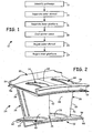
- FIG. 1 is a flow diagram of method 10 for coating a nozzle segment having multiple stator vanes disposed between an outer shroud and an inner platform (e.g., nozzle doublets and triplets).
- method 10 includes steps 12-22, and initially involves identifying pathways along the outer shroud and the inner platform that bisect the stator vanes (step 12).
- the outer shroud and the inner platform are then separated along the identified pathways (steps 14 and 16) using a suitable separation technique (e.g., wire electrical discharge machining).
- the separation of the outer shroud and the inner platform splits the nozzle segment into multiple sub-segments, where each sub-segment desirably includes one of the multiple stator vanes.
- each sub-segment includes a stator vane disposed between a portion of the outer shroud and a portion of the inner platform.
- stator vanes of the sub-segments are coated using a variety of coating techniques to form one or more coatings on the exposed surfaces of the stator vanes (step 18).
- Suitable coatings for the stator vanes include metallic protective coats (e.g., bond coats), thermal barrier coatings, and combinations thereof.
- the separation of the outer shroud and the inner platform allows the stator vanes to be placed apart from each other during the coating process, thereby allowing each stator vane to be coated with a line-of-sight coating technique. In one embodiment, this allows the resulting coatings to have substantially uniform thicknesses.
- substantially uniform thickness refers to coating thicknesses along the surface (e.g., along a surface of a stator vane) that remain within 10% of an average coating thickness for the given coating on the surface, disregarding thickness deviations due to topographical variations in the surface (e.g., cooling holes in the surface).
- an non-uniform coating thickness is desirable (e.g., controlled changes in thickness)
- the separation of the outer shroud and the inner platform allow each stator vane to be coated with the desired changes in coating thicknesses.
- the outer shroud and the inner platform are each rejoined using a suitable joining process.
- the joining process forms bond lines between the sub-segments that are desirably capable of withstanding the extreme temperatures and pressures of the turbine stages of a gas turbine engine.
- the joining process also desirably preserves the integrities of the previously applied coatings (steps 20 and 22).
- the resulting nozzle segment, having the coated stator vanes, may then be reassembled with additional nozzle segments to form an annular ring of a stationary turbine nozzle.
- the separation and rejoining of the outer shroud and the inner platform allows the coatings formed on the stator vanes to have substantially uniformly thicknesses, thereby preserving the oxidation, corrosion, and/or thermal resistances of the stator vanes during the course of operation in a gas turbine engine.
- FIGS. 2-4 are top perspective views of nozzle segment 24, which illustrate the use of method 10 (shown in FIG. 1 ) to form coatings on multiple stator vanes of nozzle segment 24.
- nozzle segment 24 is a nozzle doublet that includes vanes 26 and 28, shroud 30, and platform 32.
- Vanes 26 are 28 are turbine-stage stator vanes secured between shroud 30 and platform 32.
- Vane 26 includes interior region 34, leading edge 36, trailing edge 38, pressure sidewall 40, and suction sidewall 42, where interior region 34 is a hollow interior portion of vane 26 that directs the flow of cooling air during operation.
- Pressure sidewall 40 is the concave pressure side of vane 26, which extends between leading edge 36 and trailing edge 38.
- suction sidewall 42 is the convex suction side of vane 26, which also extends between leading edge 36 and trailing edge 38, and is the opposing surface to pressure sidewall 40.
- vane 28 includes interior region 44, leading edge 46, pressure sidewall 48, and suction sidewall 50, where interior region 44 is a hollow interior portion of vane 28 that directs the flow of cooling air during operation.
- Stator vane 28 also includes a trailing edge (not shown in FIG. 2 ) that corresponds to trailing edge 38 of stator vane 26.
- Pressure sidewall 48 is the concave pressure side of vane 28, which extends between leading edge 46 and the trailing edge of vane 28.
- suction sidewall 50 is the convex suction side of vane 28, which also extends between leading edge 46 and the trailing edge of vane 28, and is the opposing surface to pressure sidewall 46.
- Shroud 30 is an outer arcuate band secured to vanes 26 and 28, thereby allowing cooling air to enter interior regions 34 and 44 during operation.
- Shroud 30 includes leading edge 52, trailing edge 54, pressure side edge 56, and suction side edge 58, where leading edge 52 and trailing edge 54 are the upstream and downstream edges of shroud 30, respectively.
- Pressure side edge 56 and suction side edge 58 are the lateral edges of shroud 30, and are the edges that are secured to outer shrouds of adjacent nozzle segments (not shown) with leaf seal engagements to form a stationary turbine nozzle.
- platform 32 is an inner arcuate band secured to vanes 26 and 28, opposite of shroud 30.
- Platform 32 includes leading edge 60, trailing edge 62, pressure side edge 64, and suction side edge 66, where leading edge 60 and trailing edge 62 are the upstream and downstream edges of platform 32, respectively.
- Pressure side edge 64 and suction side edge 64 are the lateral edges of platform 32, and are the edges that are secured to inner platforms of adjacent nozzle segments (not shown) with leaf seal engagements to form the stationary turbine nozzle.
- pressure sidewall 40 of vane 26 and suction sidewall 50 of vane 28 are outboard surfaces that are directly accessible with a line-of-sight coating technique.
- coatings may be readily deposited on pressure sidewall 40 and suction sidewall 50 with substantially uniform thicknesses.
- suction sidewall 42 of vane 26 and pressure sidewall 48 of vane 28 are inboard surfaces, which partially shadow each other. The partial shadowing prevents line-of-sight coating techniques from evenly depositing coatings on suction sidewall 42 and pressure sidewall 48, thereby reducing coating thickness uniformity.
- the reduction in coating thickness uniformity correspondingly reduces the effectiveness of the formed coatings in providing corrosion, oxidation, and/or thermal resistance during the course of operation in a gas turbine engine.
- pathway 68 and 70 are identified along shroud 30 and platform 32, respectively.
- Pathway 68 desirably extends from leading edge 52 to trailing edge 54 of shroud 30, between vanes 26 and 28.
- pathway 70 desirably extends from leading edge 60 to trailing edge 62 of platform 32, also between vanes 26 and 28.
- pathways 68 and 70 bisect vanes 26 and 28 along shroud 30 and shroud 32, respectively. While shown as linear pathways, pathways 68 and 70 may alternatively be non-linear pathways (e.g., curved lines and angled-segmented lines).
- pathways 68 and 70 are identified at locations along shroud 30 and platform 32 that are substantially even between vanes 26 and 28. This reduces the risk of damaging vanes 26 and 28 during the separation and rejoining steps of method 10.
- nozzle segment 24 includes existing bonds lines between vanes 26 and 28 (e.g., obtained during a previous manufacturing or restoration joining process)
- pathways 68 and 70 desirably follow the existing bond lines. This allows shroud 30 and platform 32 to be separated along the existing bond lines, which preserves the alloy microstructures of shroud 30 and platform 32.
- shroud 30 and platform 32 are separated along pathways 68 and 70, pursuant to steps 14 and 16 of method 10.
- Shroud 30 and platform 32 may be separated using a variety of techniques that are suitable for cutting the alloys of shroud 30 and platform 32 without damaging vanes 26 and 28.
- shroud 30 and platform 32 are separated (simultaneously or sequentially) using wire electrical discharge machining (EDM).
- EDM wire electrical discharge machining
- nozzle segment 22 is placed in an aqueous bath, and a conductive wire is aligned with pathways 68 and 60 at leading edges 52 and 60, or at trailing edges 54 and 62.
- FIG. 3 shows nozzle segment 24 (shown in FIG. 2 ) separated into sub-segments 24a and 24b, where sub-segment 24a includes vane 26 disposed between shroud portion 30a and platform portion 32a, and sub-segment 24b includes vane 28 disposed between shroud portion 30b and platform portion 32b.
- Shroud portions 30a and 30b are the separated portions of shroud 30 (shown in FIG. 2 ), and respectively include split edges 72 and 74 formed along pathway 68 (shown in FIG. 2 ) during the separation process of step 14 of method 10.
- platform portions 32a and 32b are the separated portions of platform 32 (shown in FIG.
- vane 28 includes trailing edge 80, which is the trailing edge of vane 28, as discussed above.
- sub-segments 24a and 24b are placed apart from each other, and vanes 26 and 28 are coated to form one or more protective coatings, pursuant to step 18 of method 10.
- one or more surfaces of shroud portions 30a and 30b and platform portions 32a and 32b may be masked to prevent the formation of coatings on the masked surfaces.
- Vanes 26 and 28 may then be coated using a variety of coating techniques, including line-of-sight coating techniques.
- suitable coating techniques include electron-beam physical vapor deposition, low-pressure plasma spraying, cathodic arc deposition, vapor phase aluminide coating, pack cementation, chemical vapor deposition, electroplating, and combinations thereof.
- sub-segments 24a and 24b are each placed on a rotatable mount in a vacuum chamber containing a target anode derived of the desired coating material.
- a charged tungsten filament then emits an electron beam that contacts the target anode, thereby ionizing the material of the target anode.
- the ionized particles then precipitate onto pressure sidewall 40 and suction side wall 42 of vane 26 and onto pressure sidewall 48 and suction side wall 50 of vane 28 to form the desired metallic coatings.
- suitable materials for the metallic coatings include aluminum, platinum, MCrAlY alloys, combinations thereof.
- suitable average thicknesses for the metallic coatings on vanes 26 and 28 range from about 25 micrometers to about 200 micrometers, with particularly suitable thicknesses ranging from about 50 micrometers to about 100 micrometers.
- thermal barrier coatings may also be used to form thermal barrier coatings on vanes 26 and 28.
- Suitable materials for the thermal barrier coatings include zirconia-based materials, where the zirconia is desirably modified with a stabilizer to prevent the formation of a monoclinic phase, and pyrochlores.
- suitable stabilizers include yttria, gadolinia, calcia, ceria, magnesia, and combinations thereof.
- suitable coating thicknesses for the thermal barrier coatings on stator vanes 26 and 28 range from about 25 micrometers to about 1,000 micrometers, with particularly suitable coating thicknesses ranging from about 100 micrometers to about 500 micrometers.
- separating sub-segments 24a and 24b allows vanes 26 and 28 to be coated without interference from each other.
- pressure sidewall 40 and suction side wall 42 of vane 26, and pressure sidewall 48 and suction side wall 50 of vane 28 are each outboard surfaces that are directly accessible to the deposited coating materials.
- the coatings formed on pressure sidewalls 40 and 48, and on suction side walls 42 and 50 may have substantially uniform thicknesses. This preserves the corrosion, oxidation, and/or thermal resistance of the coatings during the course of operation in a gas turbine engine.
- split edges 72 and 74 of shroud portions 30a and 30b are substantially aligned, and such that split edges 76 and 78 of platform portions 32a and 32b are substantially aligned. Accordingly, during the rejoining process, split edges 72, 74, 76, and 78 function as faying surfaces.
- shroud portions 30a and 30b, and platform portions 32a and 32b are then each rejoined to reform shroud 30 and platform 32, respectively. As discussed above, the rejoining process forms bond lines (not shown in FIG.
- Suitable techniques for the joining process may include any process that produces a metallurgical bond, such as gas tungsten arc welding, electron beam welding, laser welding, brazing, diffusion brazing, transient liquid phase bonding, and combinations thereof.
- the rejoining process involves thermal diffusion bonding.
- split edges 72 and 74 are compressed together and are subjected to elevated temperatures to interdiffuse the materials of shroud portions 30a and 30b
- split edges 76 and 78 are compressed together and are subjected to elevated temperatures to interdiffuse the materials of platform portions 32a and 32b. This may be performed by compressing sub-segments 24a and 24b together at split edges 72 and 74 and at split edges 76 and 78, and placing the compressed sub-segments 24a/24b in a vacuum oven for a suitable temperature and duration to interdiffuse the materials.
- Suitable temperatures and durations for the thermal diffusion bonding include those that sufficiently bond shroud portions 30a and 30b, that sufficiently bond platform portions 32a and 32b, and that also substantially preserve the integrities of the coatings applied to vanes 26 and 28.
- suitable temperatures for the thermal diffusion bonding range from about 1040°C (about 1900°F) to about 1200°C (about 2200°F), with particularly suitable temperatures ranging from about 1090°C (about 2000°F) to about 1150°C (about 2100°F).
- suitable durations for the thermal diffusion bonding include durations up to about one hour, with particularly suitable durations ranging from about 10 minutes to about 30 minutes.
- the rejoining process involves a transient liquid phase bonding.
- layers of one or more brazing materials are placed between split edges 72 and 74, and between split edges 76 and 78, and sub-segments 24a and 24b are subjected to elevated temperatures.
- the elevated temperatures liquefy the brazing materials, thereby allowing the liquefied brazing materials to interdiffuse with the alloys of sub-segments 24a and 24b.
- Suitable temperatures and durations for the transient liquid phase bonding include those discussed above for the thermal diffusion bonding.
- FIG. 4 shows sub-segments 24a and 24b rejoined at bond lines 82 and 84, thereby reforming nozzle segment 24 with coated vanes 26 and 28.
- Bond lines 82 and 84 are the locations of the interdiffused materials from the joining process, and generally follow pathways 68 and 70 (shown in FIG. 2 ), respectively.
- method 10 provides a suitable means for protecting vanes 26 and 28 with coatings having substantially uniform thicknesses, and is particularly suitable for use in combination with the restoration of used nozzle segments (e.g., nozzle segment 24).
- the resulting nozzle segment 24, having coated vanes 26 and 28 may then undergo one or more post-processing steps before being reassembled with additional nozzle segments to form an annular ring of a stationary turbine nozzle.
- the formed coatings may then protect vanes 26 and 28 from oxidation, corrosion, thermal attacks during the course of operation in a gas turbine engine.
Landscapes
- Engineering & Computer Science (AREA)
- Mechanical Engineering (AREA)
- General Engineering & Computer Science (AREA)
- Chemical & Material Sciences (AREA)
- Materials Engineering (AREA)
- Turbine Rotor Nozzle Sealing (AREA)
Claims (13)
- Verfahren (10) zum Beschichten eines Düsensegments mit einer Mehrzahl von Statorleitschaufeln, die zwischen einem äußeren Mantel und einer inneren Plattform angeordnet sind, wobei das Verfahren Folgendes beinhaltet:Trennen (14, 16) des äußeren Mantels und der inneren Plattform entlang von Wegen, die eine erste Statorleitschaufel und eine zweite Statorleitschaufel der Mehrzahl von Statorleitschaufeln halbieren;Beschichten (18) der ersten Statorleitschaufel und der zweiten Statorleitschaufel unter Verwendung von Sichtlinientechniken nach dem Trennen des äußeren Mantels und der inneren Plattform;Wiederverbinden (20) des getrennten äußeren Mantels nach dem Beschichten der ersten Statorleitschaufel und der zweiten Statorleitschaufel; undWiederverbinden (22) der getrennten inneren Plattform nach dem Beschichten der ersten Statorleitschaufel und der zweiten Statorleitschaufel,dadurch gekennzeichnet,dass das Wiederverbinden (20) des getrennten äußeren Mantels und das Wiederverbinden (22) der getrennten inneren Plattform das Ausführen eines Wärmebehandlungsprozesses beinhaltet, der aus thermischem Diffusionsbonden besteht.
- Verfahren nach Anspruch 1,
wobei das Trennen (14, 16) des äußeren Mantels und der inneren Plattform entlang der Wege eine Drahterosionsbearbeitung des äußeren Mantels und der inneren Plattform entlang der Wege beinhaltet. - Verfahren nach Anspruch 1 oder 2,
wobei das Beschichten (18) der ersten Statorleitschaufel und der zweiten Statorleitschaufel das Durchführen einer physikalischen Elektronenstrahl-Gasphasenabscheidung an der ersten Statorleitschaufel und an der zweiten Statorleitschaufel beinhaltet. - Verfahren nach Anspruch 1, 2 oder 3,
wobei die erste Statorleitschaufel (26) und die zweite Statorleitschaufel (28) jeweils eine Druckseitenwand (40, 48) und eine Sogseitenwand (42, 50) aufweisen, wobei nach dem Beschichten der ersten Statorleitschaufel und der zweiten Statorleitschaufel die Druckseitenwände und die Sogseitenwände jeweils eine Beschichtung mit einer im wesentlichen gleichmäßigen Dicke aufweisen. - Verfahren nach Anspruch 1 bis 4,
wobei der Wärmebehandlungsprozess bei einer Temperatur im Bereich von etwa 1040°C bis etwa 1200°C ausgeführt wird. - Verfahren nach Anspruch 5
wobei die Temperatur des Wärmebehandlungsprozesses im Bereich von etwa 1090°C bis etwa 1150°C liegt. - Verfahren nach einem der vorhergehenden Ansprüche, aufweisend:Identifizieren (12) eines ersten Wegs entlang des äußeren Mantels, der eine erste Statorleitschaufel und eine zweite Statorleitschaufel der Mehrzahl von Statorleitschaufeln halbiert;Identifizieren (12) eines zweiten Wegs entlang der inneren Plattform, der die erste Statorleitschaufel und die zweite Statorleitschaufel halbiert;Trennen (14) des äußeren Mantels entlang des identifizierten ersten Wegs, um einen an der ersten Statorleitschaufel befestigten ersten Mantelbereich und einen an der zweiten Statorleitschaufel befestigten zweiten Mantelbereich zu bilden;Trennen (16) der inneren Plattform entlang des identifizierten zweiten Wegs, um einen an der ersten Statorleitschaufel befestigten ersten Plattformbereich und einen an der zweiten Statorleitschaufel befestigten zweiten Plattformbereich zu bilden;Bilden (18) einer ersten Beschichtung auf der ersten Statorleitschaufel nach dem Trennen des äußeren Mantels und der inneren Plattform;Bilden (18) einer zweiter Beschichtung auf der zweiten Statorleitschaufel nach dem Trennen des äußeren Mantels und der inneren Plattform;Wiederverbinden (20) des ersten Mantelbereichs und des zweiten Mantelbereichs; undWiederverbinden (22) des ersten Plattformbereichs und des zweiten Plattformbereichs.
- Verfahren nach Anspruch 7,
wobei das Trennen (14) des äußeren Mantels entlang des identifizierten ersten Wegs eine Drahterosionsbearbeitung des äußeren Mantels entlang des identifizierten ersten Wegs beinhaltet. - Verfahren nach Anspruch 7 oder 8,
wobei das Trennen (16) der inneren Plattform entlang des identifizierten zweiten Wegs eine Drahterosionsbearbeitung der inneren Plattform entlang des identifizierten zweiten Wegs beinhaltet. - Düsensegment (24), aufweisend:eine erste Statorleitschaufel (26), die eine erste Druckseitenwand und eine erste Sogseitenwand aufweist, wobei die erste Druckseitenwand und der erste Sogseitenwand jeweils eine erste Beschichtung aufweisen, die unter Verwendung von Sichtlinientechniken gebildet ist und eine im Wesentlichen gleichmäßige Dicke aufweist;eine zweite Statorleitschaufel (28), die eine zweite Druckseitenwand und eine zweite Sogseitenwand aufweist, wobei die zweite Druckseitenwand und die zweite Sogseitenwand jeweils eine zweite Beschichtung aufweisen, die unter Verwendung von Sichtlinientechniken gebildet ist und eine im Wesentlichen gleichmäßige Dicke aufweist;einen äußeren Mantel (30), der an der ersten Statorleitschaufel und der zweiten Statorleitschaufel befestigt ist, wobei der äußere Mantel eine erste Verbindungslinie aufweist, die zwischen der ersten Statorleitschaufel und der zweiten Statorleitschaufel angeordnet ist und nach dem Bilden der ersten Beschichtung und der zweiten Beschichtung gebildet ist;eine innere Plattform (32), die an der ersten Statorleitschaufel und der zweiten Statorleitschaufel an gegenüberliegenden Enden von dem äußeren Mantel befestigt ist, wobei die innere Plattform eine zweite Verbindungslinie aufweist, die zwischen der ersten Statorleitschaufel und der zweiten Statorleitschaufel angeordnet ist und nach dem Bilden der ersten Beschichtung und der zweiten Beschichtung gebildet ist, und dadurch gekennzeichnet, dass die erste Verbindungslinie und die zweite Verbindungslinie jeweils mittels eines Wärmebehandlungsprozesses gebildet sind, der eine thermische Verbindung bei einer Temperatur in einem Bereich von etwa 1040°C bis etwa 1200°C beinhaltet.
- Düsensegment nach Anspruch 10,
wobei die erste Beschichtung und die zweite Beschichtung jeweils aus mindestens einem Material gebildet sind, das aus der Gruppe bestehend aus Aluminium, Platin, MCrAIY-Legierungen, Keramikmaterialien und Kombinationen davon ausgewählt ist. - Düsensegment nach Anspruch 10 oder 11,
wobei die erste Beschichtung und die zweite Beschichtung jeweils eine durch physikalische Elektronenstrahl-Gasphasenabscheidung gebildete Beschichtung beinhalten. - Düsensegment nach Anspruch 10, 11 oder 12,
wobei die erste Beschichtung und die zweite Beschichtung jeweils eine Beschichtungsdicke im Bereich von etwa 25 Mikrometer bis etwa 1000 Mikrometer, vorzugsweise von etwa 25 Mikrometer bis etwa 200 Mikrometer, aufweisen.
Applications Claiming Priority (1)
| Application Number | Priority Date | Filing Date | Title |
|---|---|---|---|
| US12/151,102 US20090274562A1 (en) | 2008-05-02 | 2008-05-02 | Coated turbine-stage nozzle segments |
Publications (3)
| Publication Number | Publication Date |
|---|---|
| EP2113636A2 EP2113636A2 (de) | 2009-11-04 |
| EP2113636A3 EP2113636A3 (de) | 2013-09-11 |
| EP2113636B1 true EP2113636B1 (de) | 2014-12-03 |
Family
ID=40793653
Family Applications (1)
| Application Number | Title | Priority Date | Filing Date |
|---|---|---|---|
| EP09250906.6A Ceased EP2113636B1 (de) | 2008-05-02 | 2009-03-27 | Beschichtete Turbinstufendüsensegmente |
Country Status (2)
| Country | Link |
|---|---|
| US (1) | US20090274562A1 (de) |
| EP (1) | EP2113636B1 (de) |
Families Citing this family (16)
| Publication number | Priority date | Publication date | Assignee | Title |
|---|---|---|---|---|
| GB2445952B (en) * | 2007-01-25 | 2011-07-20 | Siemens Ag | A gas turbine engine |
| US20130011265A1 (en) * | 2011-07-05 | 2013-01-10 | Alstom Technology Ltd. | Chevron platform turbine vane |
| US9925623B2 (en) * | 2012-09-28 | 2018-03-27 | United Technologies Corporation | Case assembly and method |
| US9702252B2 (en) | 2012-12-19 | 2017-07-11 | Honeywell International Inc. | Turbine nozzles with slip joints and methods for the production thereof |
| WO2014130214A1 (en) * | 2013-02-22 | 2014-08-28 | United Technologies Corporation | Stator vane assembly and method therefore |
| EP2961961B1 (de) * | 2013-03-01 | 2020-09-23 | United Technologies Corporation | Verfahren zur herstellung einer schaufelgruppe und zugehörige schaufelgruppe |
| EP2971519B1 (de) | 2013-03-15 | 2020-10-28 | United Technologies Corporation | Verfahren zur bearbeitung von schaufelgruppen eines gasturbinentriebwerks |
| EP2969363B1 (de) * | 2013-03-15 | 2020-11-04 | United Technologies Corporation | Verfahren zur bearbeitung einer schaufelgruppe |
| US10822980B2 (en) * | 2013-04-11 | 2020-11-03 | Raytheon Technologies Corporation | Gas turbine engine stress isolation scallop |
| FR3009842B1 (fr) * | 2013-08-20 | 2015-08-28 | Snecma | Procede d'assemblage de deux pales d'un distributeur de turbomachine |
| WO2015088852A1 (en) * | 2013-12-13 | 2015-06-18 | United Technologies Corporation | Additive manufacturing shroud support structure |
| CZ201432A3 (cs) * | 2014-01-16 | 2015-05-27 | Vlastimil Sedláček | Způsob výroby dýzového segmentu |
| US9845524B2 (en) * | 2014-01-22 | 2017-12-19 | United Technologies Corporation | Fixture for application of coatings and method of using same |
| WO2015123268A1 (en) * | 2014-02-11 | 2015-08-20 | United Technologies Corporation | System and method for applying a metallic coating |
| US10018075B2 (en) * | 2015-04-22 | 2018-07-10 | General Electric Company | Methods for positioning neighboring nozzles of a gas turbine engine |
| US11092022B2 (en) * | 2019-11-04 | 2021-08-17 | Raytheon Technologies Corporation | Vane with chevron face |
Family Cites Families (52)
| Publication number | Priority date | Publication date | Assignee | Title |
|---|---|---|---|---|
| US2579583A (en) * | 1945-01-29 | 1951-12-25 | Allis Chalmers Mfg Co | Segmental blading |
| GB938189A (en) * | 1960-10-29 | 1963-10-02 | Ruston & Hornsby Ltd | Improvements in the construction of turbine and compressor blade elements |
| US3979085A (en) * | 1974-10-08 | 1976-09-07 | The United States Of America As Represented By The Secretary Of The Army | Guided missile using fluidic sensing and steering |
| US3975112A (en) * | 1975-06-09 | 1976-08-17 | United Technologies Corporation | Apparatus for sealing a gas turbine flow path |
| US4050133A (en) * | 1976-06-07 | 1977-09-27 | Cretella Salvatore | Method of refurbishing turbine vanes and the like |
| US4176433A (en) * | 1978-06-29 | 1979-12-04 | United Technologies Corporation | Method of remanufacturing turbine vane clusters for gas turbine engines |
| US4194869A (en) * | 1978-06-29 | 1980-03-25 | United Technologies Corporation | Stator vane cluster |
| US4285108A (en) * | 1979-02-23 | 1981-08-25 | United Technologies Corporation | Apparatus and method for refinishing turbine blade airseals |
| US4305697A (en) * | 1980-03-19 | 1981-12-15 | General Electric Company | Method and replacement member for repairing a gas turbine engine vane assembly |
| US4326833A (en) * | 1980-03-19 | 1982-04-27 | General Electric Company | Method and replacement member for repairing a gas turbine engine blade member |
| US4726101A (en) * | 1986-09-25 | 1988-02-23 | United Technologies Corporation | Turbine vane nozzle reclassification |
| US4856963A (en) * | 1988-03-23 | 1989-08-15 | United Technologies Corporation | Stator assembly for an axial flow rotary machine |
| US5174715A (en) * | 1990-12-13 | 1992-12-29 | General Electric Company | Turbine nozzle |
| US5071054A (en) * | 1990-12-18 | 1991-12-10 | General Electric Company | Fabrication of cast articles from high melting temperature superalloy compositions |
| US5269057A (en) * | 1991-12-24 | 1993-12-14 | Freedom Forge Corporation | Method of making replacement airfoil components |
| US5248240A (en) * | 1993-02-08 | 1993-09-28 | General Electric Company | Turbine stator vane assembly |
| US5636439A (en) * | 1995-05-22 | 1997-06-10 | General Electric Co. | Methods for coating and securing multi-vane nozzle segments |
| US5609469A (en) * | 1995-11-22 | 1997-03-11 | United Technologies Corporation | Rotor assembly shroud |
| US5690469A (en) * | 1996-06-06 | 1997-11-25 | United Technologies Corporation | Method and apparatus for replacing a vane assembly in a turbine engine |
| US5758416A (en) * | 1996-12-05 | 1998-06-02 | General Electric Company | Method for repairing a turbine engine vane segment |
| US6241467B1 (en) * | 1999-08-02 | 2001-06-05 | United Technologies Corporation | Stator vane for a rotary machine |
| US6425736B1 (en) * | 1999-08-09 | 2002-07-30 | United Technologies Corporation | Stator assembly for a rotary machine and method for making the stator assembly |
| US6543995B1 (en) * | 1999-08-09 | 2003-04-08 | United Technologies Corporation | Stator vane and stator assembly for a rotary machine |
| US6173491B1 (en) * | 1999-08-12 | 2001-01-16 | Chromalloy Gas Turbine Corporation | Method for replacing a turbine vane airfoil |
| US6154959A (en) * | 1999-08-16 | 2000-12-05 | Chromalloy Gas Turbine Corporation | Laser cladding a turbine engine vane platform |
| US6179567B1 (en) * | 1999-08-18 | 2001-01-30 | United Technologies Corporation | Turbomachinery blade or vane with a survivable machining datum |
| DE69927594T2 (de) * | 1999-11-03 | 2006-07-20 | Alstom Technology Ltd | Verfahren zum Beschichten und Schweissen von Leitschaufeln einer Gasturbine |
| US6785961B1 (en) * | 1999-11-12 | 2004-09-07 | General Electric Corporation | Turbine nozzle segment and method of repairing same |
| US6553665B2 (en) * | 2000-03-08 | 2003-04-29 | General Electric Company | Stator vane assembly for a turbine and method for forming the assembly |
| US6394750B1 (en) * | 2000-04-03 | 2002-05-28 | United Technologies Corporation | Method and detail for processing a stator vane |
| US6416278B1 (en) * | 2000-11-16 | 2002-07-09 | General Electric Company | Turbine nozzle segment and method of repairing same |
| US6508000B2 (en) * | 2001-02-08 | 2003-01-21 | Siemens Westinghouse Power Corporation | Transient liquid phase bonding repair for advanced turbine blades and vanes |
| US6719892B2 (en) * | 2001-05-04 | 2004-04-13 | United Technologies Corporation | Selective removal of brazing compound from joined assemblies |
| US6685431B2 (en) * | 2001-10-24 | 2004-02-03 | United Technologies Corporation | Method for repairing a turbine vane |
| US6609880B2 (en) * | 2001-11-15 | 2003-08-26 | General Electric Company | Methods and apparatus for cooling gas turbine nozzles |
| JP2003222026A (ja) * | 2002-01-30 | 2003-08-08 | Hitachi Ltd | タービン翼の製作方法およびタービン翼 |
| US6793457B2 (en) * | 2002-11-15 | 2004-09-21 | General Electric Company | Fabricated repair of cast nozzle |
| US6905308B2 (en) * | 2002-11-20 | 2005-06-14 | General Electric Company | Turbine nozzle segment and method of repairing same |
| US6969233B2 (en) * | 2003-02-27 | 2005-11-29 | General Electric Company | Gas turbine engine turbine nozzle segment with a single hollow vane having a bifurcated cavity |
| US6887041B2 (en) * | 2003-03-03 | 2005-05-03 | General Electric Company | Airfoil shape for a turbine nozzle |
| US7008178B2 (en) * | 2003-12-17 | 2006-03-07 | General Electric Company | Inboard cooled nozzle doublet |
| US7101150B2 (en) * | 2004-05-11 | 2006-09-05 | Power Systems Mfg, Llc | Fastened vane assembly |
| US7334306B2 (en) * | 2004-06-02 | 2008-02-26 | General Electric Company | Methods and apparatus for fabricating a turbine nozzle assembly |
| US20060042932A1 (en) * | 2004-08-25 | 2006-03-02 | Rosenzweig Mark A | Apparatus and method for electroplating a workpiece |
| US7121793B2 (en) * | 2004-09-09 | 2006-10-17 | General Electric Company | Undercut flange turbine nozzle |
| US7140835B2 (en) * | 2004-10-01 | 2006-11-28 | General Electric Company | Corner cooled turbine nozzle |
| US7115832B1 (en) * | 2005-07-26 | 2006-10-03 | United Technologies Corporation | Microplasma spray coating apparatus |
| US7195454B2 (en) * | 2004-12-02 | 2007-03-27 | General Electric Company | Bullnose step turbine nozzle |
| US7185433B2 (en) * | 2004-12-17 | 2007-03-06 | General Electric Company | Turbine nozzle segment and method of repairing same |
| US8327538B2 (en) * | 2005-10-17 | 2012-12-11 | General Electric Company | Methods to facilitate extending gas turbine engine useful life |
| CA2568971A1 (en) * | 2005-11-29 | 2007-05-29 | General Electric Company | Method for applying a bond coat and a thermal barrier coating over an aluminided surface |
| US7341427B2 (en) * | 2005-12-20 | 2008-03-11 | General Electric Company | Gas turbine nozzle segment and process therefor |
-
2008
- 2008-05-02 US US12/151,102 patent/US20090274562A1/en not_active Abandoned
-
2009
- 2009-03-27 EP EP09250906.6A patent/EP2113636B1/de not_active Ceased
Also Published As
| Publication number | Publication date |
|---|---|
| US20090274562A1 (en) | 2009-11-05 |
| EP2113636A3 (de) | 2013-09-11 |
| EP2113636A2 (de) | 2009-11-04 |
Similar Documents
| Publication | Publication Date | Title |
|---|---|---|
| EP2113636B1 (de) | Beschichtete Turbinstufendüsensegmente | |
| US8387245B2 (en) | Components with re-entrant shaped cooling channels and methods of manufacture | |
| US8739404B2 (en) | Turbine components with cooling features and methods of manufacturing the same | |
| US8741420B2 (en) | Component and methods of fabricating and coating a component | |
| US8047771B2 (en) | Turbine nozzles and methods of manufacturing the same | |
| US20020141869A1 (en) | Turbine blade tip having thermal barrier coating-formed micro cooling channels | |
| JP2010126812A (ja) | Tbc被覆タービン構成部品のための補修方法 | |
| EP2589754B1 (de) | Laufschaufelkomponente einer Turbomaschine | |
| US8545185B2 (en) | Turbine engine components with environmental protection for interior passages | |
| US9657580B1 (en) | Brazing tape and method of forming microchannels in a thermal barrier coating | |
| US9297267B2 (en) | System and method for removing heat from a turbine | |
| CN110325666A (zh) | 用于燃气涡轮发动机的翼型的涂层和施加涂层的方法 | |
| JP2019519684A (ja) | 改善されたコーティングシステムを備える翼形部およびその形成方法 | |
| US9316110B2 (en) | High porosity abradable coating | |
| US20150322563A1 (en) | Fixture for application of coatings and method of using same | |
| US11946389B2 (en) | Turbine rotor blade and contact surface manufacturing method | |
| EP2211021B1 (de) | Verfahren und Anordnung für Turbinenschaufeln mit Schutzschichtbeschichtung | |
| US20250243770A1 (en) | Internal aluminide coating for vanes and blades and method of manufacture | |
| US7122224B2 (en) | Methods and apparatus for turbine engine component coating | |
| EP2937514B1 (de) | Gasturbinenmotor-turbinenschaufelspitze mit beschichteter aussparung | |
| EP4524368A1 (de) | Verfahren zur wiederherstellung von legierungsverarmung um kühlbohrungen in einer schaufel | |
| US20140137408A1 (en) | Methods of fabricating and coating turbine components |
Legal Events
| Date | Code | Title | Description |
|---|---|---|---|
| PUAI | Public reference made under article 153(3) epc to a published international application that has entered the european phase |
Free format text: ORIGINAL CODE: 0009012 |
|
| AK | Designated contracting states |
Kind code of ref document: A2 Designated state(s): AT BE BG CH CY CZ DE DK EE ES FI FR GB GR HR HU IE IS IT LI LT LU LV MC MK MT NL NO PL PT RO SE SI SK TR |
|
| AX | Request for extension of the european patent |
Extension state: AL BA RS |
|
| PUAL | Search report despatched |
Free format text: ORIGINAL CODE: 0009013 |
|
| AK | Designated contracting states |
Kind code of ref document: A3 Designated state(s): AT BE BG CH CY CZ DE DK EE ES FI FR GB GR HR HU IE IS IT LI LT LU LV MC MK MT NL NO PL PT RO SE SI SK TR |
|
| AX | Request for extension of the european patent |
Extension state: AL BA RS |
|
| RIC1 | Information provided on ipc code assigned before grant |
Ipc: F01D 9/04 20060101ALI20130802BHEP Ipc: F01D 5/28 20060101AFI20130802BHEP |
|
| 17P | Request for examination filed |
Effective date: 20140311 |
|
| RBV | Designated contracting states (corrected) |
Designated state(s): AT BE BG CH CY CZ DE DK EE ES FI FR GB GR HR HU IE IS IT LI LT LU LV MC MK MT NL NO PL PT RO SE SI SK TR |
|
| AKX | Designation fees paid |
Designated state(s): DE GB |
|
| GRAP | Despatch of communication of intention to grant a patent |
Free format text: ORIGINAL CODE: EPIDOSNIGR1 |
|
| INTG | Intention to grant announced |
Effective date: 20140806 |
|
| GRAS | Grant fee paid |
Free format text: ORIGINAL CODE: EPIDOSNIGR3 |
|
| GRAA | (expected) grant |
Free format text: ORIGINAL CODE: 0009210 |
|
| AK | Designated contracting states |
Kind code of ref document: B1 Designated state(s): DE GB |
|
| REG | Reference to a national code |
Ref country code: GB Ref legal event code: FG4D |
|
| REG | Reference to a national code |
Ref country code: DE Ref legal event code: R096 Ref document number: 602009028075 Country of ref document: DE Effective date: 20150115 |
|
| REG | Reference to a national code |
Ref country code: DE Ref legal event code: R097 Ref document number: 602009028075 Country of ref document: DE |
|
| PLBE | No opposition filed within time limit |
Free format text: ORIGINAL CODE: 0009261 |
|
| STAA | Information on the status of an ep patent application or granted ep patent |
Free format text: STATUS: NO OPPOSITION FILED WITHIN TIME LIMIT |
|
| 26N | No opposition filed |
Effective date: 20150904 |
|
| REG | Reference to a national code |
Ref country code: DE Ref legal event code: R082 Ref document number: 602009028075 Country of ref document: DE Representative=s name: SCHMITT-NILSON SCHRAUD WAIBEL WOHLFROM PATENTA, DE |
|
| REG | Reference to a national code |
Ref country code: DE Ref legal event code: R082 Ref document number: 602009028075 Country of ref document: DE Representative=s name: SCHMITT-NILSON SCHRAUD WAIBEL WOHLFROM PATENTA, DE Ref country code: DE Ref legal event code: R081 Ref document number: 602009028075 Country of ref document: DE Owner name: UNITED TECHNOLOGIES CORP. (N.D.GES.D. STAATES , US Free format text: FORMER OWNER: UNITED TECHNOLOGIES CORP., HARTFORD, CONN., US |
|
| REG | Reference to a national code |
Ref country code: DE Ref legal event code: R081 Ref document number: 602009028075 Country of ref document: DE Owner name: RAYTHEON TECHNOLOGIES CORPORATION (N.D.GES.D.S, US Free format text: FORMER OWNER: UNITED TECHNOLOGIES CORP. (N.D.GES.D. STAATES DELAWARE), FARMINGTON, CONN., US |
|
| PGFP | Annual fee paid to national office [announced via postgrant information from national office to epo] |
Ref country code: GB Payment date: 20230222 Year of fee payment: 15 Ref country code: DE Payment date: 20230221 Year of fee payment: 15 |
|
| P01 | Opt-out of the competence of the unified patent court (upc) registered |
Effective date: 20230519 |
|
| REG | Reference to a national code |
Ref country code: DE Ref legal event code: R119 Ref document number: 602009028075 Country of ref document: DE |
|
| GBPC | Gb: european patent ceased through non-payment of renewal fee |
Effective date: 20240327 |
|
| PG25 | Lapsed in a contracting state [announced via postgrant information from national office to epo] |
Ref country code: DE Free format text: LAPSE BECAUSE OF NON-PAYMENT OF DUE FEES Effective date: 20241001 |
|
| PG25 | Lapsed in a contracting state [announced via postgrant information from national office to epo] |
Ref country code: GB Free format text: LAPSE BECAUSE OF NON-PAYMENT OF DUE FEES Effective date: 20240327 |
|
| PG25 | Lapsed in a contracting state [announced via postgrant information from national office to epo] |
Ref country code: GB Free format text: LAPSE BECAUSE OF NON-PAYMENT OF DUE FEES Effective date: 20240327 Ref country code: DE Free format text: LAPSE BECAUSE OF NON-PAYMENT OF DUE FEES Effective date: 20241001 |