EP2113681A2 - Procédé de contrôle d'un support hydraulique fluide MR connecté à un moteur de véhicule - Google Patents
Procédé de contrôle d'un support hydraulique fluide MR connecté à un moteur de véhicule Download PDFInfo
- Publication number
- EP2113681A2 EP2113681A2 EP09158466A EP09158466A EP2113681A2 EP 2113681 A2 EP2113681 A2 EP 2113681A2 EP 09158466 A EP09158466 A EP 09158466A EP 09158466 A EP09158466 A EP 09158466A EP 2113681 A2 EP2113681 A2 EP 2113681A2
- Authority
- EP
- European Patent Office
- Prior art keywords
- fluid
- pressure
- current
- determining
- difference
- Prior art date
- Legal status (The legal status is an assumption and is not a legal conclusion. Google has not performed a legal analysis and makes no representation as to the accuracy of the status listed.)
- Granted
Links
Images
Classifications
-
- F—MECHANICAL ENGINEERING; LIGHTING; HEATING; WEAPONS; BLASTING
- F16—ENGINEERING ELEMENTS AND UNITS; GENERAL MEASURES FOR PRODUCING AND MAINTAINING EFFECTIVE FUNCTIONING OF MACHINES OR INSTALLATIONS; THERMAL INSULATION IN GENERAL
- F16F—SPRINGS; SHOCK-ABSORBERS; MEANS FOR DAMPING VIBRATION
- F16F13/00—Units comprising springs of the non-fluid type as well as vibration-dampers, shock-absorbers, or fluid springs
- F16F13/04—Units comprising springs of the non-fluid type as well as vibration-dampers, shock-absorbers, or fluid springs comprising both a plastics spring and a damper, e.g. a friction damper
- F16F13/26—Units comprising springs of the non-fluid type as well as vibration-dampers, shock-absorbers, or fluid springs comprising both a plastics spring and a damper, e.g. a friction damper characterised by adjusting or regulating devices responsive to exterior conditions
- F16F13/30—Units comprising springs of the non-fluid type as well as vibration-dampers, shock-absorbers, or fluid springs comprising both a plastics spring and a damper, e.g. a friction damper characterised by adjusting or regulating devices responsive to exterior conditions comprising means for varying fluid viscosity, e.g. of magnetic or electrorheological fluids
- F16F13/305—Units comprising springs of the non-fluid type as well as vibration-dampers, shock-absorbers, or fluid springs comprising both a plastics spring and a damper, e.g. a friction damper characterised by adjusting or regulating devices responsive to exterior conditions comprising means for varying fluid viscosity, e.g. of magnetic or electrorheological fluids magnetorheological
-
- F—MECHANICAL ENGINEERING; LIGHTING; HEATING; WEAPONS; BLASTING
- F16—ENGINEERING ELEMENTS AND UNITS; GENERAL MEASURES FOR PRODUCING AND MAINTAINING EFFECTIVE FUNCTIONING OF MACHINES OR INSTALLATIONS; THERMAL INSULATION IN GENERAL
- F16F—SPRINGS; SHOCK-ABSORBERS; MEANS FOR DAMPING VIBRATION
- F16F15/00—Suppression of vibrations in systems; Means or arrangements for avoiding or reducing out-of-balance forces, e.g. due to motion
- F16F15/002—Suppression of vibrations in systems; Means or arrangements for avoiding or reducing out-of-balance forces, e.g. due to motion characterised by the control method or circuitry
Definitions
- the present invention relates generally to hydraulic mounts, and more particularly to a method for controlling an MR-fluid (magnetorheological-fluid) hydraulic mount connected to a vehicle engine.
- MR-fluid hydraulic mounts include those which are attachable to first and second motor-vehicle components (such as an automobile engine or transmission and an automobile body/frame) and which have a pumping chamber and a reservoir chamber.
- the pumping and reservoir chambers are separated by a partition plate having a through hole.
- These mounts also have an electric coil which magnetically influences the through hole.
- Magnetorheological fluid is placed in the pumping and reservoir chambers and in the through hole.
- MR-fluid hydraulic-mounts examples are found in U.S. Patent Serial No. 6,622,995 and in US Patent Application Publication No. 2005/0230890 .
- An example of a hydraulic mount having an integral controller is found in US Patent Application Publication No. 2005/0029720 .
- a first method of the invention is for controlling an MR-fluid hydraulic mount connected to a vehicle engine.
- the mount includes an internal MR-fluid cavity.
- the mount includes a partition plate assembly partitioning the cavity into first and second MR-fluid chambers.
- the partition plate assembly has an orifice extending from the first MR-fluid chamber to the second MR-fluid chamber.
- the mount includes an electric coil positioned to magnetically influence the orifice.
- the first method includes steps a) through d). Step a) includes, when the vehicle engine is at idle, determining a reference pressure as a fluid pressure within the second MR-fluid chamber.
- Step b) includes, when the vehicle engine is above idle, calculating a delta pressure as a difference between a previous fluid pressure and a current fluid pressure within the second MR-fluid chamber.
- Step c) includes determining a first dead-band value using at least a difference between the reference pressure and the current fluid pressure.
- Step d) includes, when the delta pressure is greater than the first dead-band value, determining a first command electric current to be applied to the electric coil using at least the difference between the reference pressure and the current fluid pressure and applying the first command electric current to the electric coil.
- a second method of the invention is for controlling an MR-fluid hydraulic mount connected to a vehicle engine.
- the mount includes an internal MR-fluid cavity.
- the mount includes a partition plate assembly partitioning the cavity into first and second MR-fluid chambers.
- the mount includes an MR-fluid pressure sensor in fluid communication with the second MR-fluid chamber.
- the partition plate assembly has an orifice extending from the first MR-fluid chamber to the second MR-fluid chamber.
- the mount includes an electric coil positioned to magnetically influence the orifice.
- the method includes steps a) through d).
- Step a) includes, when the vehicle engine is at idle, determining a reference pressure as a fluid pressure within the second MR-fluid chamber using the MR-fluid pressure sensor.
- Step b) includes, when the vehicle engine is above idle, calculating a delta pressure as a difference between a previous fluid pressure and a current fluid pressure within the second MR-fluid chamber, wherein the previous and current fluid pressures are obtained using the MR-fluid pressure sensor.
- Step c) includes determining a first dead-band value using at least a difference between the reference pressure and the current fluid pressure.
- Step d) includes, when the delta pressure is greater than the first dead-band value, determining a first command electric current to be applied to the electric coil using at least the difference between the reference pressure and the current fluid pressure and applying the first command electric current to the electric coil.
- a third method of the invention is for controlling an MR-fluid hydraulic mount connected to a vehicle engine.
- the mount includes an internal MR-fluid cavity.
- the mount includes a partition plate assembly partitioning the cavity into first and second MR-fluid chambers.
- the partition plate assembly has an orifice extending from the first MR-fluid chamber to the second MR-fluid chamber.
- the mount includes an electric coil positioned to magnetically influence the orifice.
- the third method includes steps a) through c). Step a) includes, when the vehicle engine is at idle, determining a reference pressure as a fluid pressure within the second MR-fluid chamber.
- Step b) includes, when the vehicle engine is above idle, determining a command electric current to be applied to the electric coil using at least a difference between the reference pressure and a current fluid pressure within the second MR-fluid chamber.
- Step c) includes applying the command electric output current to the electric coil.
- the MR-fluid hydraulic mount installed in a vehicle is controlled by using at least a fluid pressure within the second MR-fluid chamber obtained by using the MR-fluid pressure sensor.
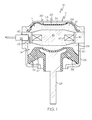
- Figure 1 is a longitudinal cross-sectional schematic view of an embodiment of an MR-fluid (magnetorheological-fluid) hydraulic mount of the invention
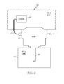
- Figure 2 is a diagram showing the mount of figure 1 attached to a vehicle body and a vehicle engine;
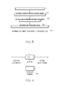
- Figure 3 is a flow chart of a first method for controlling an MR-fluid hydraulic mount, such as the mount of figures 1-2 ;
- Figure 4 is a diagram of a low-pass filter which can be used to filter a delta pressure in performing the first method of figure 3 .
- FIG. 1 A first expression of the embodiment of figure 1-2 is for apparatus 10 including an MR-fluid (magnetorheological-fluid) hydraulic mount 12.
- the mount 12 includes an internal MR-fluid cavity 14 and a partition plate assembly 16.
- the partition plate assembly 16 partitions the cavity 14 into first and second MR-fluid chambers 18 and 20.
- the mount 12 is adapted to receive an MR-fluid pressure sensor 22 in fluid communication with the second MR-fluid chamber 20.
- the mount 12 includes a base plate 24 and a housing 26, wherein the partition plate assembly 16 is disposed between and fixedly attached to the base plate 24 and the housing 26.
- the mount 12 includes an MR-fluid-sealing assembly 28 including a first portion 30 and a second portion 32, wherein the first portion 30 partially defines the first MR-fluid chamber 18 and wherein the second portion 32 partially defines the second MR-fluid chamber 20.
- the first portion 30 includes a flexible diaphragm 34 which is disposed between the base plate 24 and the partition plate assembly 16.
- the second portion 32 includes a flexible molded assembly 36 which is less flexible than the diaphragm 34 and which is attached to the housing 26.
- the mount 12 includes a mounting stud assembly 38 which is attached to the molded assembly 36.
- the partition plate assembly 16 includes an orifice 40 extending from the first MR-fluid chamber 18 to the second MR-fluid chamber 20, and the mount 12 includes an electric coil 42 disposed to magnetically influence the orifice 40.
- the base plate 24 is adapted to be attached to a vehicle body 44
- the mounting stud assembly 38 is adapted to be attached to a vehicle engine 46 (providing an engine hanging mount)
- the MR-fluid pressure sensor 22 is operatively connectable (such as by a cable 47) to a vehicle computer 48 adapted to determine a command electric current to be applied to the electric coil 42.
- the partition plate assembly 16 includes a port 50 adapted to receive the MR-fluid pressure sensor 22.
- the partition plate assembly 16 includes a passageway 52 extending from the port 50 to the second MR-fluid chamber 20.
- the housing 26 includes a port (not shown) adapted to receive the MR-fluid pressure sensor 22.
- Other examples are left to the artisan.
- the partition plate assembly 16 may be thick or thin and may be monolithic or made of a plurality of parts.
- the orifice 40 is disposed radially outward of the electric coil 42, and the partition plate assembly 16 is devoid of any decoupler and is devoid of any non-MR-fluid orifice.
- the first MR-fluid chamber 18 is a reservoir chamber and the second MR-fluid chamber 20 is a pumping chamber.
- a second expression of the embodiment of figures 1-2 is for apparatus 10 including an MR-fluid hydraulic mount 12.
- the mount 12 includes an internal MR-fluid cavity 14, a partition plate assembly 16, and an MR-fluid pressure sensor 22.
- the partition plate assembly 16 partitions the cavity into first and second MR-fluid chambers 18 and 20.
- the MR-fluid pressure sensor 22 is in fluid communication with the second MR-fluid chamber 20.
- the MR-fluid pressure sensor 22 is attached to the partition plate assembly 16.
- the partition plate assembly 16 includes a passageway 52 extending from the MR-fluid pressure sensor 22 to the second MR-fluid chamber 20.
- a first method of the invention is for controlling an MR-fluid hydraulic mount 12 connected to a vehicle engine 46.
- the mount 12 includes an internal MR-fluid cavity 14 and includes a partition plate assembly 16 partitioning the cavity 14 into first and second MR-fluid chambers 18 and 20.
- the partition plate assembly 16 has an orifice 40 extending from the first MR-fluid chamber 18 to the second MR-fluid chamber 20, and the mount 12 includes an electric coil 42 disposed to magnetically influence the orifice 40.
- the first method includes steps a) through d). Step a) is labeled as "Determine Reference Pressure For Idle Engine" in block 54 of figure 3 .
- Step a) includes, when the vehicle engine 46 is at idle, determining a reference pressure as a fluid pressure within the second MR-fluid chamber 20.
- Step b) is labeled as "Calculate Delta Pressure For Above-Idle Engine” in block 56 of figure 3 .
- Step b) includes, when the vehicle engine 46 is above idle, calculating a delta pressure as a difference between a previous fluid pressure and a current fluid pressure within the second MR-fluid chamber 20.
- Step c) is labeled as "Determine First Dead-Band Value" in block 58 of figure 3 .
- Step c) includes determining a first dead-band value using at least a difference between the reference pressure and the current fluid pressure.
- Step d) is labeled as "Determine First Current To Be Applied To The Electric Coil" in block 60 of figure 3 .
- Step d) includes, when the delta pressure is greater than the first dead-band value, determining a first command electric current to be applied to the electric coil 42 using at least the difference between the reference pressure and the current fluid pressure and applying the first command electric current to the electric coil 42.
- step a) is performed every time the vehicle engine 46 is at idle. In another variation, step a) is performed one time during an engine cycle (engine turn on to engine turn off) the first time the vehicle engine 46 is at idle.
- the first method also includes determining a second dead-band value using at least the difference between the reference pressure and the current fluid pressure.
- step d) sets the first command electric current to zero when the difference between the reference pressure and the current fluid pressure is not greater than the second dead-band value.
- step e) includes, when the delta pressure is not greater than the first dead-band value, setting the first command electric current to zero.
- step e) includes, when the delta pressure is not greater than the first dead-band value, determining a second command electric current to be applied to the electric coil 42 using at least the difference between the reference pressure and the current pressure and applying the second command electric current to the electric coil 42.
- step c) includes determining the first dead-band value using at least the difference between the reference pressure and the current pressure for a particular vehicle event.
- step c) includes determining the first dead-band value using at least the difference between the reference pressure and the current pressure for the particular vehicle event and for a particular vehicle speed.
- An example of a vehicle-speed-dependent vehicle event is a rough road.
- the first and second dead-band values are experimentally determined (and stored in lookup tables) for desirable driver/passenger comfort and desirable vehicle performance for each vehicle model for different values of delta pressure.
- the first and second command electric currents are also experimentally determined (and stored in lookup tables) for desirable driver/passenger comfort and desirable vehicle performance for each vehicle model for different values of the difference between the reference pressure and the current fluid pressure. It is noted that a positive delta pressure indicates the mount 12 is undergoing compression and that a negative delta pressure indicates the mount 12 is undergoing rebound.
- a time interval of substantially one millisecond exists between the previous fluid pressure and the current fluid pressure.
- the first and second MR-fluid chambers 18 and 20 and the orifice 40 (and the passageway 52) contain MR fluid 66.
- a second method of the invention is for controlling an MR-fluid hydraulic mount 12 connected to a vehicle engine 46.
- the mount 12 includes an internal MR-fluid cavity 14 and a partition plate assembly 16 partitioning the cavity 14 into first and second MR-fluid chambers 18 and 20.
- the mount 12 includes an MR-fluid pressure sensor 22 in fluid communication with the second MR-fluid chamber 20.
- the partition plate assembly 16 has an orifice 40 extending from the first MR-fluid chamber 18 to the second MR-fluid chamber 20.
- the mount 12 includes an electric coil 42 disposed to magnetically influence the orifice 40.
- the second method includes steps a) through d).
- Step a) includes, when the vehicle engine 46 is at idle, determining a reference pressure as a fluid pressure within the second MR-fluid chamber 20 using the MR-fluid pressure sensor 22.
- Step b) includes; when the vehicle engine 46 is above idle, calculating a delta pressure as a difference between a previous fluid pressure and a current fluid pressure within the second MR-fluid chamber 20, wherein the previous and current fluid pressures are obtained using the MR-fluid pressure sensor 22.
- Step c) includes determining a first dead-band value using at least a difference between the reference pressure and the current fluid pressure.
- Step d) includes, when the delta pressure is greater than the first dead-band value, determining a first command electric current to be applied to the electric coil 42 using at least the difference between the reference pressure and the current fluid pressure and applying the first command electric current to the electric coil 42.
- a third method of the invention which is broader than the first and second methods, is for controlling an MR-fluid hydraulic mount 12 connected to a vehicle engine 46.
- the mount 12 includes an internal MR-fluid cavity 14 and includes a partition plate assembly 16 partitioning the cavity 14 into first and second MR-fluid chambers 18 and 20.
- the partition plate assembly 16 has an orifice 40 extending from the first MR-fluid chamber 18 to the second MR-fluid chamber 20.
- the mount 12 includes an electric coil 42 disposed to magnetically influence the orifice 40
- the third method includes steps a) through c). Step a) includes, when the vehicle engine 46 is at idle, determining a reference pressure as a fluid pressure within the second MR-fluid chamber 20.
- Step b) includes, when the vehicle engine 46 is above idle, determining a command electric current to be applied to the electric coil 42 using at least a difference between the reference pressure and a current fluid pressure within the second MR-fluid chamber 20.
- Step c) includes applying the command electric output current to the electric coil.
- the mount 12 includes an MR-fluid pressure sensor 22 in fluid communication with the second MR-fluid chamber 20, and the reference, previous and current fluid pressures are obtained using the MR-fluid pressure sensor 22.
- the MR-fluid hydraulic mount is installed in a vehicle and is controlled by using at least a fluid pressure within the second MR-fluid chamber obtained by using the MR-fluid pressure sensor. This avoids problems of controlling the mount using a position or velocity sensor to determine compression and rebound of the mount, such problems including noise, reliability of the position/velocity sensor arm attachment, packaging of the position/velocity sensor, and assembly cost of the position/velocity sensor.
Landscapes
- Engineering & Computer Science (AREA)
- General Engineering & Computer Science (AREA)
- Mechanical Engineering (AREA)
- Physics & Mathematics (AREA)
- Acoustics & Sound (AREA)
- Aviation & Aerospace Engineering (AREA)
- Combined Devices Of Dampers And Springs (AREA)
- Arrangement Or Mounting Of Propulsion Units For Vehicles (AREA)
Applications Claiming Priority (1)
| Application Number | Priority Date | Filing Date | Title |
|---|---|---|---|
| US12/150,931 US20090276098A1 (en) | 2008-05-01 | 2008-05-01 | Method for controlling an MR-fluid hydraulic mount connected to a vehicle engine |
Publications (3)
| Publication Number | Publication Date |
|---|---|
| EP2113681A2 true EP2113681A2 (fr) | 2009-11-04 |
| EP2113681A3 EP2113681A3 (fr) | 2010-11-03 |
| EP2113681B1 EP2113681B1 (fr) | 2011-10-12 |
Family
ID=40940384
Family Applications (1)
| Application Number | Title | Priority Date | Filing Date |
|---|---|---|---|
| EP09158466A Not-in-force EP2113681B1 (fr) | 2008-05-01 | 2009-04-22 | Procédé de contrôle d'un support hydraulique fluide MR connecté à un moteur de véhicule |
Country Status (3)
| Country | Link |
|---|---|
| US (1) | US20090276098A1 (fr) |
| EP (1) | EP2113681B1 (fr) |
| AT (1) | ATE528533T1 (fr) |
Cited By (5)
| Publication number | Priority date | Publication date | Assignee | Title |
|---|---|---|---|---|
| US9290252B1 (en) | 2015-01-12 | 2016-03-22 | Brunswick Corporation | Systems and methods for controlling trim position of a marine propulsion device on a marine vessel |
| US9341008B1 (en) | 2014-11-26 | 2016-05-17 | Brunswick Corporation | Hinge assemblies for a cowl of an outboard motor |
| US9802688B1 (en) | 2014-12-17 | 2017-10-31 | Brunswick Corporation | Systems and methods for mounting a propulsion device with respect to a marine vessel |
| US10967946B1 (en) | 2014-12-17 | 2021-04-06 | Brunswick Corporation | Systems and methods for mounting a propulsion device with respect to a marine vessel |
| CN118150052A (zh) * | 2024-05-09 | 2024-06-07 | 山东康姆勒发电机有限公司 | 一种柴油发电机组管道密封性能测试机 |
Families Citing this family (8)
| Publication number | Priority date | Publication date | Assignee | Title |
|---|---|---|---|---|
| US20090273128A1 (en) * | 2008-05-01 | 2009-11-05 | Bodie Mark O | Apparatus including an MR-fluid hydraulic mount |
| FI123240B (fi) * | 2011-04-19 | 2012-12-31 | Waertsilae Finland Oy | Järjestely ja menetelmä polttomoottorin suuntauksen säilyttämiseksi sekä menetelmä polttomoottorin suuntaamiseksi ja sen suuntauksen säilyttämiseksi |
| KR101223447B1 (ko) | 2011-07-22 | 2013-01-17 | 현대자동차주식회사 | Mr유체가 봉입된 엔진마운트용 오리피스플레이트 |
| KR101263009B1 (ko) | 2011-11-24 | 2013-05-13 | 현대자동차주식회사 | Mr유체가 봉입된 엔진마운트용 오리피스플레이트 |
| CN103225666B (zh) * | 2013-04-02 | 2015-07-22 | 合肥工业大学 | 基于磁流变液特性的变刚度变阻尼吸振器 |
| US10160303B2 (en) | 2016-07-07 | 2018-12-25 | Beijingwest Industries Co., Ltd. | Control system for an active powertrain mount |
| JP6576414B2 (ja) * | 2017-12-04 | 2019-09-18 | 本田技研工業株式会社 | サブフレーム用のマウント |
| JP2020139547A (ja) * | 2019-02-27 | 2020-09-03 | 本田技研工業株式会社 | 可変剛性防振装置 |
Citations (5)
| Publication number | Priority date | Publication date | Assignee | Title |
|---|---|---|---|---|
| US20020153647A1 (en) | 2001-04-23 | 2002-10-24 | Delphi Technologies Inc. | Hydraulic mount and control method |
| US6622995B2 (en) | 2001-05-16 | 2003-09-23 | Delphi Technologies, Inc. | Hydraulic mount with magnetorheological fluid |
| US20050029720A1 (en) | 2003-08-07 | 2005-02-10 | Bodie Mark O. | Bi-state hydraulic mount with integral controller |
| US20050230890A1 (en) | 2004-04-16 | 2005-10-20 | Tewani Sanjiv G | Magnetorheological-fluid hydraulic mount |
| WO2008052726A1 (fr) | 2006-11-02 | 2008-05-08 | Dr. Ing. H.C. F. Porsche Aktiengesellschaft | Dispositif et procédé pour l'asservissement d'un élément de palier |
Family Cites Families (6)
| Publication number | Priority date | Publication date | Assignee | Title |
|---|---|---|---|---|
| US5284330A (en) * | 1992-06-18 | 1994-02-08 | Lord Corporation | Magnetorheological fluid devices |
| US6035878A (en) * | 1997-09-22 | 2000-03-14 | Fisher Controls International, Inc. | Diagnostic device and method for pressure regulator |
| US6754571B2 (en) * | 2001-07-30 | 2004-06-22 | Delphi Technologies, Inc. | Control of magnetorheological engine mount |
| US6598885B2 (en) * | 2001-10-23 | 2003-07-29 | Liquidspring Technologies, Inc. | Single valve control of damping and stiffness in a liquid spring system |
| US6639375B2 (en) * | 2001-10-30 | 2003-10-28 | Harold Beck And Sons, Inc. | Control device and method for controlling a control element |
| US6880483B2 (en) * | 2003-02-07 | 2005-04-19 | Delphi Technologies, Inc. | Active seat suspension for watercraft |
-
2008
- 2008-05-01 US US12/150,931 patent/US20090276098A1/en not_active Abandoned
-
2009
- 2009-04-22 AT AT09158466T patent/ATE528533T1/de not_active IP Right Cessation
- 2009-04-22 EP EP09158466A patent/EP2113681B1/fr not_active Not-in-force
Patent Citations (5)
| Publication number | Priority date | Publication date | Assignee | Title |
|---|---|---|---|---|
| US20020153647A1 (en) | 2001-04-23 | 2002-10-24 | Delphi Technologies Inc. | Hydraulic mount and control method |
| US6622995B2 (en) | 2001-05-16 | 2003-09-23 | Delphi Technologies, Inc. | Hydraulic mount with magnetorheological fluid |
| US20050029720A1 (en) | 2003-08-07 | 2005-02-10 | Bodie Mark O. | Bi-state hydraulic mount with integral controller |
| US20050230890A1 (en) | 2004-04-16 | 2005-10-20 | Tewani Sanjiv G | Magnetorheological-fluid hydraulic mount |
| WO2008052726A1 (fr) | 2006-11-02 | 2008-05-08 | Dr. Ing. H.C. F. Porsche Aktiengesellschaft | Dispositif et procédé pour l'asservissement d'un élément de palier |
Cited By (7)
| Publication number | Priority date | Publication date | Assignee | Title |
|---|---|---|---|---|
| US9341008B1 (en) | 2014-11-26 | 2016-05-17 | Brunswick Corporation | Hinge assemblies for a cowl of an outboard motor |
| US9802688B1 (en) | 2014-12-17 | 2017-10-31 | Brunswick Corporation | Systems and methods for mounting a propulsion device with respect to a marine vessel |
| US10967946B1 (en) | 2014-12-17 | 2021-04-06 | Brunswick Corporation | Systems and methods for mounting a propulsion device with respect to a marine vessel |
| US11472528B1 (en) | 2014-12-17 | 2022-10-18 | Brunswick Corporation | Systems and methods for mounting a propulsion device with respect to a marine vessel |
| US11623720B1 (en) | 2014-12-17 | 2023-04-11 | Brunswick Corporation | Systems and methods for mounting a propulsion device with respect to a marine vessel |
| US9290252B1 (en) | 2015-01-12 | 2016-03-22 | Brunswick Corporation | Systems and methods for controlling trim position of a marine propulsion device on a marine vessel |
| CN118150052A (zh) * | 2024-05-09 | 2024-06-07 | 山东康姆勒发电机有限公司 | 一种柴油发电机组管道密封性能测试机 |
Also Published As
| Publication number | Publication date |
|---|---|
| ATE528533T1 (de) | 2011-10-15 |
| US20090276098A1 (en) | 2009-11-05 |
| EP2113681B1 (fr) | 2011-10-12 |
| EP2113681A3 (fr) | 2010-11-03 |
Similar Documents
| Publication | Publication Date | Title |
|---|---|---|
| EP2113681B1 (fr) | Procédé de contrôle d'un support hydraulique fluide MR connecté à un moteur de véhicule | |
| US11529835B2 (en) | Electronically controlled external damper reservoir | |
| JP2020526446A (ja) | ブレーキシステム | |
| EP0752331A2 (fr) | Commande pour suspension de véhicule automobile | |
| KR20140131390A (ko) | 브레이크 시스템을 작동시키는 방법 및 브레이크 시스템 | |
| US9573575B2 (en) | Method for operating a brake booster of a vehicle and control device for a break booster of a vehicle | |
| US20100121548A1 (en) | Correction method for the correction of characteristic curves for analogized hydraulic valves in motor vehicle braking systems | |
| KR20150095736A (ko) | 자동차 브레이크 시스템의 공압 브레이크 부스터를 위한 진공 공급 방법 | |
| US20140372004A1 (en) | Vehicle brake hydraulic pressure controller | |
| KR101978004B1 (ko) | 압력 설정 정확도를 최적화하는 방법 | |
| JP2013519580A (ja) | 車両の液圧式ブレーキシステムを作動する方法および車両の液圧式ブレーキシステムのための制御装置 | |
| CN110550009B (zh) | 用于控制液压制动系统的方法 | |
| US9550482B2 (en) | Control device for a braking system of a vehicle, and method for operating a braking system of a vehicle | |
| EP2113680A2 (fr) | Appareil incluant un support hydraulique fluide MR | |
| US20060113837A1 (en) | Vehicle motion control apparatus | |
| US9248816B2 (en) | Hydraulic unit with variable damping | |
| US7853387B2 (en) | Controller for operation of vehicle and control method for the same | |
| CN116096610B (zh) | 对车辆的配备有机动化的活塞缸设备的制动系统进行参数估计的设备和方法 | |
| CN107310370B (zh) | 主动传动系悬置的控制系统及控制主动传动系悬置的方法 | |
| KR20190039285A (ko) | 잠김 방지 조절 프로세스를 실행하도록 설계된 브레이크 시스템의 전기 기계 브레이크 부스터를 작동시키기 위한 제어 장치 및 방법 | |
| US11447115B2 (en) | Brake fluid pressure control device | |
| KR101243078B1 (ko) | 차량용 전자제어유닛 | |
| US20240416702A1 (en) | Method for controlling a hydraulic actuator of an active chassis | |
| JPH0953480A (ja) | トラクション制御装置 | |
| CN108137013B (zh) | 电子制动压力调节系统 |
Legal Events
| Date | Code | Title | Description |
|---|---|---|---|
| PUAI | Public reference made under article 153(3) epc to a published international application that has entered the european phase |
Free format text: ORIGINAL CODE: 0009012 |
|
| AK | Designated contracting states |
Kind code of ref document: A2 Designated state(s): AT BE BG CH CY CZ DE DK EE ES FI FR GB GR HR HU IE IS IT LI LT LU LV MC MK MT NL NO PL PT RO SE SI SK TR |
|
| PUAL | Search report despatched |
Free format text: ORIGINAL CODE: 0009013 |
|
| AK | Designated contracting states |
Kind code of ref document: A3 Designated state(s): AT BE BG CH CY CZ DE DK EE ES FI FR GB GR HR HU IE IS IT LI LT LU LV MC MK MT NL NO PL PT RO SE SI SK TR |
|
| AX | Request for extension of the european patent |
Extension state: AL BA RS |
|
| 17P | Request for examination filed |
Effective date: 20110411 |
|
| GRAP | Despatch of communication of intention to grant a patent |
Free format text: ORIGINAL CODE: EPIDOSNIGR1 |
|
| RIC1 | Information provided on ipc code assigned before grant |
Ipc: F16F 15/00 20060101ALI20110506BHEP Ipc: F16F 13/30 20060101AFI20110506BHEP |
|
| RAP1 | Party data changed (applicant data changed or rights of an application transferred) |
Owner name: BWI COMPANY LIMITED S.A. Owner name: DR. ING. H.C. F. PORSCHE AKTIENGESELLSCHAFT |
|
| GRAS | Grant fee paid |
Free format text: ORIGINAL CODE: EPIDOSNIGR3 |
|
| GRAA | (expected) grant |
Free format text: ORIGINAL CODE: 0009210 |
|
| AK | Designated contracting states |
Kind code of ref document: B1 Designated state(s): AT BE BG CH CY CZ DE DK EE ES FI FR GB GR HR HU IE IS IT LI LT LU LV MC MK MT NL NO PL PT RO SE SI SK TR |
|
| REG | Reference to a national code |
Ref country code: GB Ref legal event code: FG4D |
|
| REG | Reference to a national code |
Ref country code: CH Ref legal event code: EP |
|
| REG | Reference to a national code |
Ref country code: IE Ref legal event code: FG4D |
|
| REG | Reference to a national code |
Ref country code: DE Ref legal event code: R096 Ref document number: 602009002998 Country of ref document: DE Effective date: 20111215 |
|
| REG | Reference to a national code |
Ref country code: NL Ref legal event code: VDEP Effective date: 20111012 |
|
| LTIE | Lt: invalidation of european patent or patent extension |
Effective date: 20111012 |
|
| REG | Reference to a national code |
Ref country code: AT Ref legal event code: MK05 Ref document number: 528533 Country of ref document: AT Kind code of ref document: T Effective date: 20111012 |
|
| PG25 | Lapsed in a contracting state [announced via postgrant information from national office to epo] |
Ref country code: LT Free format text: LAPSE BECAUSE OF FAILURE TO SUBMIT A TRANSLATION OF THE DESCRIPTION OR TO PAY THE FEE WITHIN THE PRESCRIBED TIME-LIMIT Effective date: 20111012 Ref country code: NO Free format text: LAPSE BECAUSE OF FAILURE TO SUBMIT A TRANSLATION OF THE DESCRIPTION OR TO PAY THE FEE WITHIN THE PRESCRIBED TIME-LIMIT Effective date: 20120112 Ref country code: IS Free format text: LAPSE BECAUSE OF FAILURE TO SUBMIT A TRANSLATION OF THE DESCRIPTION OR TO PAY THE FEE WITHIN THE PRESCRIBED TIME-LIMIT Effective date: 20120212 Ref country code: BE Free format text: LAPSE BECAUSE OF FAILURE TO SUBMIT A TRANSLATION OF THE DESCRIPTION OR TO PAY THE FEE WITHIN THE PRESCRIBED TIME-LIMIT Effective date: 20111012 |
|
| PG25 | Lapsed in a contracting state [announced via postgrant information from national office to epo] |
Ref country code: GR Free format text: LAPSE BECAUSE OF FAILURE TO SUBMIT A TRANSLATION OF THE DESCRIPTION OR TO PAY THE FEE WITHIN THE PRESCRIBED TIME-LIMIT Effective date: 20120113 Ref country code: LV Free format text: LAPSE BECAUSE OF FAILURE TO SUBMIT A TRANSLATION OF THE DESCRIPTION OR TO PAY THE FEE WITHIN THE PRESCRIBED TIME-LIMIT Effective date: 20111012 Ref country code: NL Free format text: LAPSE BECAUSE OF FAILURE TO SUBMIT A TRANSLATION OF THE DESCRIPTION OR TO PAY THE FEE WITHIN THE PRESCRIBED TIME-LIMIT Effective date: 20111012 Ref country code: PT Free format text: LAPSE BECAUSE OF FAILURE TO SUBMIT A TRANSLATION OF THE DESCRIPTION OR TO PAY THE FEE WITHIN THE PRESCRIBED TIME-LIMIT Effective date: 20120213 Ref country code: SE Free format text: LAPSE BECAUSE OF FAILURE TO SUBMIT A TRANSLATION OF THE DESCRIPTION OR TO PAY THE FEE WITHIN THE PRESCRIBED TIME-LIMIT Effective date: 20111012 Ref country code: SI Free format text: LAPSE BECAUSE OF FAILURE TO SUBMIT A TRANSLATION OF THE DESCRIPTION OR TO PAY THE FEE WITHIN THE PRESCRIBED TIME-LIMIT Effective date: 20111012 Ref country code: HR Free format text: LAPSE BECAUSE OF FAILURE TO SUBMIT A TRANSLATION OF THE DESCRIPTION OR TO PAY THE FEE WITHIN THE PRESCRIBED TIME-LIMIT Effective date: 20111012 |
|
| PG25 | Lapsed in a contracting state [announced via postgrant information from national office to epo] |
Ref country code: CY Free format text: LAPSE BECAUSE OF FAILURE TO SUBMIT A TRANSLATION OF THE DESCRIPTION OR TO PAY THE FEE WITHIN THE PRESCRIBED TIME-LIMIT Effective date: 20111012 |
|
| PG25 | Lapsed in a contracting state [announced via postgrant information from national office to epo] |
Ref country code: BG Free format text: LAPSE BECAUSE OF FAILURE TO SUBMIT A TRANSLATION OF THE DESCRIPTION OR TO PAY THE FEE WITHIN THE PRESCRIBED TIME-LIMIT Effective date: 20120112 Ref country code: SK Free format text: LAPSE BECAUSE OF FAILURE TO SUBMIT A TRANSLATION OF THE DESCRIPTION OR TO PAY THE FEE WITHIN THE PRESCRIBED TIME-LIMIT Effective date: 20111012 Ref country code: EE Free format text: LAPSE BECAUSE OF FAILURE TO SUBMIT A TRANSLATION OF THE DESCRIPTION OR TO PAY THE FEE WITHIN THE PRESCRIBED TIME-LIMIT Effective date: 20111012 Ref country code: CZ Free format text: LAPSE BECAUSE OF FAILURE TO SUBMIT A TRANSLATION OF THE DESCRIPTION OR TO PAY THE FEE WITHIN THE PRESCRIBED TIME-LIMIT Effective date: 20111012 Ref country code: DK Free format text: LAPSE BECAUSE OF FAILURE TO SUBMIT A TRANSLATION OF THE DESCRIPTION OR TO PAY THE FEE WITHIN THE PRESCRIBED TIME-LIMIT Effective date: 20111012 |
|
| PLBE | No opposition filed within time limit |
Free format text: ORIGINAL CODE: 0009261 |
|
| STAA | Information on the status of an ep patent application or granted ep patent |
Free format text: STATUS: NO OPPOSITION FILED WITHIN TIME LIMIT |
|
| PG25 | Lapsed in a contracting state [announced via postgrant information from national office to epo] |
Ref country code: RO Free format text: LAPSE BECAUSE OF FAILURE TO SUBMIT A TRANSLATION OF THE DESCRIPTION OR TO PAY THE FEE WITHIN THE PRESCRIBED TIME-LIMIT Effective date: 20111012 Ref country code: IT Free format text: LAPSE BECAUSE OF FAILURE TO SUBMIT A TRANSLATION OF THE DESCRIPTION OR TO PAY THE FEE WITHIN THE PRESCRIBED TIME-LIMIT Effective date: 20111012 Ref country code: PL Free format text: LAPSE BECAUSE OF FAILURE TO SUBMIT A TRANSLATION OF THE DESCRIPTION OR TO PAY THE FEE WITHIN THE PRESCRIBED TIME-LIMIT Effective date: 20111012 |
|
| 26N | No opposition filed |
Effective date: 20120713 |
|
| REG | Reference to a national code |
Ref country code: DE Ref legal event code: R097 Ref document number: 602009002998 Country of ref document: DE Effective date: 20120713 |
|
| PG25 | Lapsed in a contracting state [announced via postgrant information from national office to epo] |
Ref country code: MC Free format text: LAPSE BECAUSE OF NON-PAYMENT OF DUE FEES Effective date: 20120430 |
|
| REG | Reference to a national code |
Ref country code: IE Ref legal event code: MM4A |
|
| PG25 | Lapsed in a contracting state [announced via postgrant information from national office to epo] |
Ref country code: IE Free format text: LAPSE BECAUSE OF NON-PAYMENT OF DUE FEES Effective date: 20120422 Ref country code: AT Free format text: LAPSE BECAUSE OF FAILURE TO SUBMIT A TRANSLATION OF THE DESCRIPTION OR TO PAY THE FEE WITHIN THE PRESCRIBED TIME-LIMIT Effective date: 20111012 |
|
| PG25 | Lapsed in a contracting state [announced via postgrant information from national office to epo] |
Ref country code: MK Free format text: LAPSE BECAUSE OF FAILURE TO SUBMIT A TRANSLATION OF THE DESCRIPTION OR TO PAY THE FEE WITHIN THE PRESCRIBED TIME-LIMIT Effective date: 20111012 |
|
| PG25 | Lapsed in a contracting state [announced via postgrant information from national office to epo] |
Ref country code: ES Free format text: LAPSE BECAUSE OF FAILURE TO SUBMIT A TRANSLATION OF THE DESCRIPTION OR TO PAY THE FEE WITHIN THE PRESCRIBED TIME-LIMIT Effective date: 20120123 |
|
| PG25 | Lapsed in a contracting state [announced via postgrant information from national office to epo] |
Ref country code: FI Free format text: LAPSE BECAUSE OF FAILURE TO SUBMIT A TRANSLATION OF THE DESCRIPTION OR TO PAY THE FEE WITHIN THE PRESCRIBED TIME-LIMIT Effective date: 20111012 |
|
| PG25 | Lapsed in a contracting state [announced via postgrant information from national office to epo] |
Ref country code: MT Free format text: LAPSE BECAUSE OF FAILURE TO SUBMIT A TRANSLATION OF THE DESCRIPTION OR TO PAY THE FEE WITHIN THE PRESCRIBED TIME-LIMIT Effective date: 20111012 |
|
| REG | Reference to a national code |
Ref country code: CH Ref legal event code: PL |
|
| PG25 | Lapsed in a contracting state [announced via postgrant information from national office to epo] |
Ref country code: LI Free format text: LAPSE BECAUSE OF NON-PAYMENT OF DUE FEES Effective date: 20130430 Ref country code: CH Free format text: LAPSE BECAUSE OF NON-PAYMENT OF DUE FEES Effective date: 20130430 |
|
| PG25 | Lapsed in a contracting state [announced via postgrant information from national office to epo] |
Ref country code: TR Free format text: LAPSE BECAUSE OF FAILURE TO SUBMIT A TRANSLATION OF THE DESCRIPTION OR TO PAY THE FEE WITHIN THE PRESCRIBED TIME-LIMIT Effective date: 20111012 |
|
| PG25 | Lapsed in a contracting state [announced via postgrant information from national office to epo] |
Ref country code: LU Free format text: LAPSE BECAUSE OF NON-PAYMENT OF DUE FEES Effective date: 20120422 |
|
| PG25 | Lapsed in a contracting state [announced via postgrant information from national office to epo] |
Ref country code: HU Free format text: LAPSE BECAUSE OF FAILURE TO SUBMIT A TRANSLATION OF THE DESCRIPTION OR TO PAY THE FEE WITHIN THE PRESCRIBED TIME-LIMIT Effective date: 20090422 |
|
| REG | Reference to a national code |
Ref country code: FR Ref legal event code: PLFP Year of fee payment: 8 |
|
| REG | Reference to a national code |
Ref country code: FR Ref legal event code: PLFP Year of fee payment: 9 |
|
| REG | Reference to a national code |
Ref country code: FR Ref legal event code: PLFP Year of fee payment: 10 |
|
| PGFP | Annual fee paid to national office [announced via postgrant information from national office to epo] |
Ref country code: GB Payment date: 20220303 Year of fee payment: 14 |
|
| PGFP | Annual fee paid to national office [announced via postgrant information from national office to epo] |
Ref country code: FR Payment date: 20220308 Year of fee payment: 14 |
|
| PGFP | Annual fee paid to national office [announced via postgrant information from national office to epo] |
Ref country code: DE Payment date: 20220302 Year of fee payment: 14 |
|
| P01 | Opt-out of the competence of the unified patent court (upc) registered |
Effective date: 20230526 |
|
| REG | Reference to a national code |
Ref country code: DE Ref legal event code: R119 Ref document number: 602009002998 Country of ref document: DE |
|
| GBPC | Gb: european patent ceased through non-payment of renewal fee |
Effective date: 20230422 |
|
| PG25 | Lapsed in a contracting state [announced via postgrant information from national office to epo] |
Ref country code: GB Free format text: LAPSE BECAUSE OF NON-PAYMENT OF DUE FEES Effective date: 20230422 |
|
| PG25 | Lapsed in a contracting state [announced via postgrant information from national office to epo] |
Ref country code: GB Free format text: LAPSE BECAUSE OF NON-PAYMENT OF DUE FEES Effective date: 20230422 Ref country code: FR Free format text: LAPSE BECAUSE OF NON-PAYMENT OF DUE FEES Effective date: 20230430 Ref country code: DE Free format text: LAPSE BECAUSE OF NON-PAYMENT OF DUE FEES Effective date: 20231103 |