EP2113692B2 - Soupape à clapet - Google Patents
Soupape à clapet Download PDFInfo
- Publication number
- EP2113692B2 EP2113692B2 EP09004906.5A EP09004906A EP2113692B2 EP 2113692 B2 EP2113692 B2 EP 2113692B2 EP 09004906 A EP09004906 A EP 09004906A EP 2113692 B2 EP2113692 B2 EP 2113692B2
- Authority
- EP
- European Patent Office
- Prior art keywords
- housing
- seal
- flap
- accordance
- spring
- Prior art date
- Legal status (The legal status is an assumption and is not a legal conclusion. Google has not performed a legal analysis and makes no representation as to the accuracy of the status listed.)
- Active
Links
Images



Classifications
-
- F—MECHANICAL ENGINEERING; LIGHTING; HEATING; WEAPONS; BLASTING
- F16—ENGINEERING ELEMENTS AND UNITS; GENERAL MEASURES FOR PRODUCING AND MAINTAINING EFFECTIVE FUNCTIONING OF MACHINES OR INSTALLATIONS; THERMAL INSULATION IN GENERAL
- F16K—VALVES; TAPS; COCKS; ACTUATING-FLOATS; DEVICES FOR VENTING OR AERATING
- F16K1/00—Lift valves or globe valves, i.e. cut-off apparatus with closure members having at least a component of their opening and closing motion perpendicular to the closing faces
- F16K1/16—Lift valves or globe valves, i.e. cut-off apparatus with closure members having at least a component of their opening and closing motion perpendicular to the closing faces with pivoted closure-members
- F16K1/18—Lift valves or globe valves, i.e. cut-off apparatus with closure members having at least a component of their opening and closing motion perpendicular to the closing faces with pivoted closure-members with pivoted discs or flaps
- F16K1/22—Lift valves or globe valves, i.e. cut-off apparatus with closure members having at least a component of their opening and closing motion perpendicular to the closing faces with pivoted closure-members with pivoted discs or flaps with axis of rotation crossing the valve member, e.g. butterfly valves
- F16K1/226—Shaping or arrangements of the sealing
- F16K1/2268—Sealing means for the axis of rotation
-
- F—MECHANICAL ENGINEERING; LIGHTING; HEATING; WEAPONS; BLASTING
- F02—COMBUSTION ENGINES; HOT-GAS OR COMBUSTION-PRODUCT ENGINE PLANTS
- F02D—CONTROLLING COMBUSTION ENGINES
- F02D9/00—Controlling engines by throttling air or fuel-and-air induction conduits or exhaust conduits
- F02D9/04—Controlling engines by throttling air or fuel-and-air induction conduits or exhaust conduits concerning exhaust conduits
Definitions
- the present invention relates to a flap valve according to claim 1, in particular for use in the hot area of exhaust systems for internal combustion engines, having a housing with at least one fluid inlet opening and at least one fluid outlet opening, a closure flap which is rotatably arranged in the housing and which comprises a rotation transmission means which can be passed through an opening in a wall of the housing and can be connected in a torque-proof manner to an actuating element provided outside the housing, and a seal acting between the housing and the rotary transmission means to seal off the interior of the housing from the outside, with means arranged further outside than the seal, viewed in the direction of the actuating element, in particular spring means, being provided, through which the seal seen the housing and / or the rotation transmission means is urged, and wherein the means are supported on the one hand on the rotation transmission means and on the other hand on the housing.
- Such a flap valve is, for example, from DE 103 29 336 A1 known.
- document DE 10 2006 048 713 A1 discloses a valve device which can be used as a butterfly valve in an exhaust manifold center part of an internal combustion engine of a motor vehicle.
- the valve device has a valve housing with a through-channel, a valve flap for opening and closing the through-channel, a shaft which is arranged transversely to the through-channel and in the valve housing and to which the valve flap is attached in a rotationally fixed manner, and bearings for the rotatable and gas-tight mounting of the shaft.
- a spring positions the shaft in the axial direction in the valve housing.
- Flap valves are used in exhaust systems for internal combustion engines in particular in order to regulate the exhaust gas back pressure as a function of the engine, for example as a function of the speed. Such flap valves must be sealed to the outside, so that no exhaust gases penetrate uncontrolled to the outside. Sealing is particularly important when such a flap valve is used in front of an exhaust gas catalytic converter, particularly in the hot area of exhaust systems, since the exhaust gases there are at least not yet completely cleaned.
- the means by which the seal is urged against the housing and/or the rotary transmission means are thermally stressed in such a way that accelerated aging of the means can occur, thereby reducing the service life of the means .
- the invention is based on the object of specifying a flap valve of the type mentioned at the outset, in which the thermal aging behavior is improved.
- a long service life should also be made possible in the hot area of exhaust systems.
- the housing comprises a separate housing part for accommodating the seal, and the means are arranged outside the separate housing part. Due to the separate housing part, the seal can be shielded from the outside and the heat transfer to the means can thereby be reduced.
- the seal is also designed as a bearing means for the radial bearing of the closure flap, in particular as a slide bearing. This double or triple function of the seal means that separate bearing means can be saved.
- the means are supported on the side of the separate housing part that faces away from the rest of the housing. This makes it possible to use small-sized means.
- the means can enclose the separate housing part and be supported on a housing section of the housing adjacent to it.
- the means are supported on the rotary transmission means via a positive connection.
- the positive connection can in particular ensure that the axial position of the means along the rotation transmission means is limited and the means are captively held on the rotation transmission means.
- the means are biased under pressure so that the rotation transmission means is pushed outwards.
- the form-fitting connection can be formed, for example, by a retaining ring which engages in a circumferential groove formed on the rotation transmission means. Alternatively, however, it can also be provided that the means themselves engage in a recess formed on the rotation transmission means.
- the seal preferably has annular sloping surfaces which are inclined relative to the axis of rotation of the closure flap and which interact with corresponding sloping surfaces on the housing and/or on the rotary transmission means.
- a normal to an inner sealing surface and a normal to an outer sealing surface of the seal run parallel to one another, in particular coincide.
- the rotation transmission means has a shoulder to form a sealing surface, the shoulder preferably having an annular outer circumferential surface inclined to the axis of rotation of the closure flap. A prestressing of the means can be transferred to the seal via the shoulder of the rotation transmission means in such a way that the seal is pressed against the housing and/or the rotation transmission means.
- a heat shield in particular made of ceramic, for example zirconium dioxide, is preferably arranged between the interior of the housing and the seal and/or the separate housing part and the means.
- a heat shield with a low thermal conductivity value can further reduce heat transfer from the exhaust gas to components of the flap valve that are further outside. It is particularly preferred if the heat shield between the interior of the housing and the seal is designed at the same time as a bearing means for the radial bearing of the closure flap, in particular as a bearing bush.
- the spring means can be designed as a spring clip, torsion spring, helical spring, telescopic spring or disk spring.
- a spring clip can have two legs which are supported against one another at an otherwise open end of the spring clip.
- a telescopic spring has proven to be particularly insensitive to dirt.
- another spring can also be used.
- means are provided by which the seal is only partially rotated when the closure flap is rotated.
- the seal rubs on the housing and/or the rotary transmission means, as a result of which the elements pressed against one another are ground onto one another, resulting in a high degree of tightness.
- the invention further relates to a double flap, in particular for use in the hot area of exhaust systems for internal combustion engines, with two flap valves each as described above, which are arranged one behind the other in the direction of flow.
- Non-limiting exemplary embodiments of the invention are illustrated in the drawing and are described below.
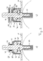
- the flap valve shown comprises a housing 11 with a fluid inlet opening 13 and a fluid outlet opening 15.
- a closure flap 17 with two wings 19, 21, of which in 1 only the vane 19 can be seen, rotatably mounted between a first position in which the vanes 19, 21 completely close the fluid outlet opening 15 and a second position in which the fluid outlet opening 15 is completely open.
- the closure flap 17 is shown in the second position.
- the two wings 19, 21 of the closure flap 17 are connected to a shaft 23 of the closure flap 17 in a rotationally fixed manner.
- the shaft 23 is guided through opposite sides of the housing 11 at both ends. on the inside 1
- a radial bearing 25 is provided for receiving the lower part 27 of the shaft 23 protruding downwards from the housing 11 .
- the radial bearing 25 is surrounded by a separate bearing housing 29 in a completely gas-tight manner.
- the shaft 23 is guided through an opening 31 in a wall 33 of the housing 11 on the upper side.
- a storage space 35 for storing the upper part 37 of the shaft 23 protruding from the housing 11 .
- the storage space 35 is surrounded by a separate housing part 39 which is welded to the rest of the housing 11 in a gas-tight manner.
- the shaft 23 completely passes through the bearing space 35 and is through an opening 41 ( Figure 3a ) in an upper wall 43 of the separate housing part 39 to the outside.
- a plate spring 45 which is prestressed under pressure and has a central opening through which the shaft 23 is guided.
- the disc spring 45 is supported on the one hand by a ceramic disc 47 on the upper wall 43 of the separate housing part 39 and on the other hand by a disc 79 and a retaining ring 49 which engages in a circumferential groove formed on the shaft 23.
- the shaft 23 can be actuated via the end of the upper part 37 of the shaft 23 which is outside the housing 11, in particular outside the separate housing part 39 and beyond the disc spring 45.
- a sealing ring 51 arranged at a distance from the plate spring 45 for sealing the interior of the housing from the outside.
- the outer peripheral surface 53 and the wall section 57 as well as the inner sealing surface 54 and the outer sealing surface 56 are each inclined by 45° to the axis of rotation of the closure flap 17, although in principle other angles of inclination are also possible.
- the embodiment described has the effect that the sealing ring 51 also acts as a plain bearing for the axial and radial bearing of the shaft 23 of the closure flap 17 .
- the sealing ring 51 Seen in cross section through one side, the sealing ring 51 has a square basic shape with beveled corners, with a normal to the inner sealing surface 54 and a normal to the outer sealing surface 56 coinciding, so that the two pressure points at which the sealing ring 51 presses against the shaft 23 and the separate housing part 39 is urged, on a common normal 71 ( Figure 3b ), with respect to a mean perimeter 73 ( Figure 3b ) of the sealing ring 51 are arranged opposite one another, as a result of which particularly good sealing and storage can be achieved.
- the shaft 23 also includes two carriers 61 which are arranged opposite one another with respect to the axis of rotation of the closure flap 17 and which are each located in engage an angular recess of the sealing ring 51 in order to partially rotate the sealing ring 51 when the shaft 37 is rotated.
- the size of the angular recess determines the angular range over which the sealing ring 51 does not rotate with the shaft 37 .
- a ceramic disc 63 is arranged between the interior of the housing 11 and the sealing ring 51, which, like the above-mentioned ceramic disc 47 arranged between the upper wall 43 of the separate housing part 39 and the disc spring 45, is designed as a heat shield in order to prevent heat transfer from the exhaust gas from the interior of the housing to components of the flap valve located behind the heat shield.
- the ceramic disk 63 between the interior of the housing and the sealing ring 51 is designed in such a way that it also acts as a bearing bush for the radial mounting of the closing flap 17 .
- a telescopic spring 65 is used instead of a disc spring.
- the design of the flap valve corresponds to Figure 3a however, according to the design of the flap valve 1 .
- Figure 3b shows a further embodiment of a flap valve according to the invention, but only the deviations of this embodiment compared to those in FIGS 1 and 3 illustrated embodiments are to be explained.
- the embodiment according to Figure 3b comprises a helical spring 67 instead of a plate spring or a telescopic spring 1 and 3a
- the helical spring 67 is supported on the shaft 23 but not on the upper wall 43 of the separate housing part 39 . Rather, the inner diameter of the helical spring 67 is selected in such a way that the helical spring 67 encloses the separate housing part 39 and is supported on an adjacent housing section of the housing 11 .
- the springs 75, 77, 79, 81, 83 shown can be used, with the shaft 23 being guided through an opening 69 of the springs 45, 65, 67, 75, 77, 79, 81, 83, and with the springs 75, 77 , 79, 81 are each supported on the separate housing part 39 and via the retaining ring 49, in particular without a washer 79, on the shaft 23.
- the spring clip 75 shown comprises two flat legs which run essentially parallel to one another in the unloaded state. Due to the flat design of the legs, reliable support on both sides, both against the shaft 23 and against the separate housing part 39, can be guaranteed. Around the spring clip 75 from Figure 4a to bias under pressure, the two legs at the open end of the spring clip 75 are pressed together.
- the spring clip 75 shown differs from that in Figure 4a shown spring clip characterized in that the two legs are supported on the otherwise open end of the spring clip 75 against each other. Around the spring clip 75 from Figure 4b preload under pressure, the two legs are pressed together in the middle.
- Spring 81 shown differs from that in Figure 4b spring clip shown in that the two legs are firmly connected to each other at the otherwise open end of a spring clip.
- Figure 4d shows a spring 79 which is designed in the manner of a disc spring.
- the spring 79 has a rotationally symmetrical basic shape with two opposing support surfaces and a circumferential, outwardly bulging, spring-elastic area arranged in between. the rotational symmetry being interrupted by recesses formed in the bulged area and regularly distributed around the axis of the opening 69 .
- the leg spring 77 shown comprises two cylindrical torsion springs, the free ends of which are connected to one another in such a way that a common upper leg and a common lower leg are formed, with which the leg spring 77 can be supported on the separate housing part 39 and via the retaining ring 49 on the shaft 23.
- Fig. 4f 12 shows a spring 83 which, on a lower side, comprises spring plates which are arranged symmetrically around an axis and with which the spring 83 can be supported on the separate housing part 39 .
- support claws distributed symmetrically about the axis, which engage in a corresponding depression or groove of the shaft 23 to support the spring 83 on the shaft 23 .
- the spring means are each designed as a compression spring. In principle, however, it is also possible for the means to be pretensioned under tension.
- a coil spring could be preloaded in tension and attached at a first end to the top wall of housing 11 and at a second end to shaft 23 .
- the fact that the means are supported on the housing and the shaft and not on the seal according to the invention means that the thermal load on the means can be reduced. This effect can be further enhanced by locating the means at a distance from the seal and locating the means outside of the separate housing part.
Landscapes
- Engineering & Computer Science (AREA)
- General Engineering & Computer Science (AREA)
- Mechanical Engineering (AREA)
- Chemical & Material Sciences (AREA)
- Combustion & Propulsion (AREA)
- Lift Valve (AREA)
- Exhaust Silencers (AREA)
Claims (13)
- Vanne à clapet, en particulier pour l'utilisation dans la région chaude d'installations de gaz d'échappement pour moteurs à combustion interne, comprenant un boîtier (11, 39) avec au moins une ouverture d'entrée de fluide (13) et au moins une ouverture de sortie de fluide (15), un clapet obturateur (17) agencé en rotation dans le boîtier (11, 39), qui comprend un moyen de transmission de rotation (23), lequel est guidé à travers une ouverture (31) dans une paroi (33) du boîtier (11, 39) et est susceptible d'être relié solidairement en rotation avec un élément d'actionnement prévu à l'extérieur du boîtier (11, 39), et un joint (51) actif entre le boîtier (11) et le moyen de transmission de rotation (23) pour étancher l'intérieur du boîtier vis-à-vis de l'extérieur,dans laquelleil est prévu des moyens (45, 65, 67, 75, 77, 81, 83), en particulier des moyens à ressort, qui, vus en direction de l'élément d'actionnement, sont agencés plus à l'extérieur que le joint (51), grâce auxquels le joint (51) est poussé contre le boîtier (11, 39) et/ou contre le moyen de transmission de rotation (23), etlesdits moyens s'appuient d'une part contre le moyen de transmission de rotation (23) et d'autre part contre le boîtier (11, 39),caractérisée en ce queles moyens (45, 65, 67, 75, 77, 81, 83) ne s'appuient pas contre le joint (51),le joint (51) est réalisé simultanément à titre de moyen formant palier pour le montage radial du clapet obturateur (17), en particulier à titre de palier à coulissement,le boîtier (11, 39) comprend une partie de boîtier séparée (39) pour loger le joint (51), etles moyens (45, 65, 67, 75, 77, 81, 83) sont agencés à l'extérieur de la partie de boîtier séparée (39).
- Vanne à clapet selon la revendication 1,
caractérisée en ce que
les moyens (45, 65, 67, 75, 77, 81, 83) s'appuient sur le côté, détourné du reste du boîtier (11), de la partie de boîtier séparée (39). - Vanne à clapet selon la revendication 1,
caractérisée en ce que
les moyens (45, 65, 67, 75, 77, 81, 83) entourent la partie de boîtier séparée (39) et s'appuient sur un tronçon, voisin de celle-ci, du boîtier (11, 39). - Vanne à clapet selon l'une au moins des revendications précédentes,
caractérisée en ce que
les moyens (45, 65, 67, 75, 77, 81, 83) s'appuient sur le moyen de transmission de rotation (23) via une liaison à coopération de formes. - Vanne à clapet selon l'une au moins des revendications précédentes,
caractérisée en ce que
le joint (51) est réalisé simultanément à titre de moyen formant palier pour le montage axial du clapet obturateur (17), en particulier à titre de palier à coulissement. - Vanne à clapet selon la revendication 5,
caractérisée en ce que
le joint (51) comporte des surfaces obliques annulaires, inclinées par rapport à l'axe de rotation du clapet obturateur (17), qui coopèrent avec des surfaces obliques correspondantes (53, 57) sur le boîtier (11, 39) et/ou sur le moyen de transmission de rotation (23). - Vanne à clapet selon la revendication 6,
caractérisée en ce que, dans une coupe transversale à travers un côté du joint (51), une normale (71) à une surface d'étanchéité intérieure et une normale (71) à une surface d'étanchéité extérieure du joint (51) s'étendent parallèlement l'une à l'autre, et sont en particulier coïncidentes. - Vanne à clapet selon l'une au moins des revendications précédentes,
caractérisée en ce que
le moyen de transmission de rotation (23) comprend un talon (55) pour la réalisation d'une surface d'étanchéité, ledit talon (55) présentant de préférence une surface périphérique extérieure (53) de forme annulaire inclinée par rapport à l'axe de rotation du clapet obturateur (17). - Vanne à clapet selon l'une au moins des revendications précédentes,
caractérisée en ce que
un bouclier thermique (47, 63), en particulier en céramique, est agencé entre l'intérieur du boîtier et le joint (51) et/ou entre la partie de boîtier séparée (39) et les moyens (45, 65, 67, 75, 77, 81, 83). - Vanne à clapet selon la revendication 9,
caractérisée en ce que
le bouclier thermique (63) entre l'intérieur du boîtier et le joint (51) est réalisé simultanément à titre de moyen formant palier pour le montage radial du clapet obturateur (17), en particulier à titre de douille-palier. - Vanne à clapet selon l'une au moins des revendications précédentes,
caractérisée en ce que
les moyens à ressort sont réalisés sous forme de pince-ressort (75), de ressort à bras (77), de ressort à boudin (67), de ressort télescopique (65) ou de rondelle-ressort (45). - Vanne à clapet selon l'une au moins des revendications précédentes,
caractérisée en ce que
il est prévu des moyens (61) grâce auxquels le joint (51) est entraîné seulement partiellement conjointement en rotation lors de la rotation du clapet obturateur (17). - Double clapet, en particulier pour l'utilisation dans la région chaude d'installations de gaz d'échappement pour moteurs à combustion interne, comprenant deux vannes à clapet réalisées chacune selon l'une au moins des revendications précédentes, qui sont agencées l'une derrière l'autre en direction d'écoulement.
Applications Claiming Priority (1)
| Application Number | Priority Date | Filing Date | Title |
|---|---|---|---|
| DE202008005992U DE202008005992U1 (de) | 2008-04-30 | 2008-04-30 | Klappenventil |
Publications (3)
| Publication Number | Publication Date |
|---|---|
| EP2113692A1 EP2113692A1 (fr) | 2009-11-04 |
| EP2113692B1 EP2113692B1 (fr) | 2011-12-14 |
| EP2113692B2 true EP2113692B2 (fr) | 2022-09-14 |
Family
ID=39688659
Family Applications (1)
| Application Number | Title | Priority Date | Filing Date |
|---|---|---|---|
| EP09004906.5A Active EP2113692B2 (fr) | 2008-04-30 | 2009-04-02 | Soupape à clapet |
Country Status (3)
| Country | Link |
|---|---|
| EP (1) | EP2113692B2 (fr) |
| AT (1) | ATE537391T1 (fr) |
| DE (1) | DE202008005992U1 (fr) |
Families Citing this family (11)
| Publication number | Priority date | Publication date | Assignee | Title |
|---|---|---|---|---|
| DE102009052423B4 (de) * | 2009-11-10 | 2011-07-28 | Heinrich Gillet GmbH, 67480 | Ventilklappenvorrichtung |
| DE102011101948B4 (de) | 2010-05-19 | 2016-08-11 | Tenneco Gmbh | Verfahren zur Herstellung einer Ventilklappenvorrichtung |
| DE102012212998B4 (de) * | 2012-07-24 | 2023-09-07 | Friedrich Boysen Gmbh & Co. Kg | Lagersystem für eine Welle |
| DE102012111810B4 (de) | 2012-12-05 | 2015-02-05 | Pierburg Gmbh | Klappenvorrichtung für eine Verbrennungskraftmaschine |
| DE102012111948B4 (de) | 2012-12-07 | 2015-05-28 | Pierburg Gmbh | Klappenvorrichtung für eine Verbrennungskraftmaschine |
| DE102013013387A1 (de) | 2013-03-10 | 2014-09-11 | Kohlhage Automotive GmbH & Co. KG | Lagerung für eine Welle, insbesondere bei einer Ventileinheit, mit einer solchen Lagerung ausgestattete Ventileinheit und Verfahren zur Herstellung |
| DE102013106627B4 (de) | 2013-06-25 | 2015-02-05 | Pierburg Gmbh | Klappenvorrichtung für eine Verbrennungskraftmaschine |
| FR3048048B1 (fr) | 2016-02-22 | 2018-11-30 | Faurecia Systemes D'echappement | Vanne pour une ligne d'echappement de vehicule |
| CN108953624B (zh) * | 2018-08-13 | 2023-08-15 | 四川大学 | 锁子甲式翻板阀 |
| IT202100004703A1 (it) * | 2021-03-01 | 2022-09-01 | Marelli Europe Spa | Valvola a farfalla motorizzata per un condotto di scarico |
| IT202200004115A1 (it) | 2022-03-04 | 2023-09-04 | Marelli Europe Spa | Valvola a farfalla motorizzata e raffreddata per un condotto di scarico |
Citations (3)
| Publication number | Priority date | Publication date | Assignee | Title |
|---|---|---|---|---|
| JPH0791247A (ja) † | 1993-09-24 | 1995-04-04 | Mikuni Corp | デュアルモードマフラのバタフライバルブ |
| US6273119B1 (en) † | 2000-03-06 | 2001-08-14 | Delphi Technologies, Inc. | Exhaust control valve and method of manufacturing same |
| DE19526144B4 (de) † | 1995-07-18 | 2008-10-23 | Pierburg Gmbh | Anordnung einer Drosselklappe |
Family Cites Families (7)
| Publication number | Priority date | Publication date | Assignee | Title |
|---|---|---|---|---|
| DE1179049B (de) * | 1959-07-16 | 1964-10-01 | Zahnradfabrik Friedrichshafen | Auspuffmotorbremse, bestehend aus einer Bremsklappe, die eine durchgehende Bohrung zur Aufnahme einer Klappenwelle aufweist, und aus einem ungeteilten Gehaeuse |
| ZA803042B (en) * | 1979-08-08 | 1981-05-27 | Krupp Polysius Ag | A pendulum flap |
| IT220044Z2 (it) * | 1990-07-09 | 1993-06-09 | Fasani Spa | Valvola a farfalla per l'itercettazione di regolazione di fluidi |
| US5988589A (en) * | 1996-07-17 | 1999-11-23 | Mowill; R. Jan | Air valve assembly including split-shaft and seal arrangement |
| DE10329336A1 (de) | 2003-06-30 | 2005-01-20 | Friedrich Boysen Gmbh & Co. Kg | Klappenventil |
| WO2006003017A1 (fr) * | 2004-07-07 | 2006-01-12 | Faurecia Abgastechnik Gmbh | Soupape a clapet pour le circuit d'echappement d'un vehicule automobile |
| DE102006048713A1 (de) * | 2006-10-14 | 2008-04-17 | Daimler Ag | Ventilvorrichtung |
-
2008
- 2008-04-30 DE DE202008005992U patent/DE202008005992U1/de not_active Expired - Lifetime
-
2009
- 2009-04-02 AT AT09004906T patent/ATE537391T1/de active
- 2009-04-02 EP EP09004906.5A patent/EP2113692B2/fr active Active
Patent Citations (3)
| Publication number | Priority date | Publication date | Assignee | Title |
|---|---|---|---|---|
| JPH0791247A (ja) † | 1993-09-24 | 1995-04-04 | Mikuni Corp | デュアルモードマフラのバタフライバルブ |
| DE19526144B4 (de) † | 1995-07-18 | 2008-10-23 | Pierburg Gmbh | Anordnung einer Drosselklappe |
| US6273119B1 (en) † | 2000-03-06 | 2001-08-14 | Delphi Technologies, Inc. | Exhaust control valve and method of manufacturing same |
Also Published As
| Publication number | Publication date |
|---|---|
| DE202008005992U1 (de) | 2008-08-14 |
| EP2113692A1 (fr) | 2009-11-04 |
| ATE537391T1 (de) | 2011-12-15 |
| EP2113692B1 (fr) | 2011-12-14 |
Similar Documents
| Publication | Publication Date | Title |
|---|---|---|
| EP2113692B1 (fr) | Soupape à clapet | |
| EP1493951B1 (fr) | Vanne papillon | |
| EP2726719B1 (fr) | Dispositif à soupape destiné à réguler un flux de gaz d'échappement d'un moteur à combustion interne | |
| DE102017202137B4 (de) | Klappeneinrichtung zum Öffnen und Schließen eines Wastegatekanals in einem Turbinengehäuse eines Turboladers sowie Turbolader | |
| EP2609319B1 (fr) | Soupape de recyclage de gaz d'échappement pour un moteur à combustion interne | |
| EP1771653B1 (fr) | Soupape destinee a etre utilisee dans une canalisation de carburant d'un vehicule automobile | |
| WO1996021815A1 (fr) | Soupape d'arret ou d'etranglement a clapet rotatif | |
| DE102011077766A1 (de) | Betätigungseinrichtung für ein Abgasstrom-Steuerelement eines Abgasturboladers | |
| EP2929166A1 (fr) | Dispositif de clapet pour un moteur à combustion interne | |
| EP2445605A1 (fr) | Dispositif de filtration | |
| EP2929165B1 (fr) | Dispositif à clapet pour moteur à combustion interne | |
| DE112005001467B4 (de) | Klappenventil für die Abgasanlage eines Kraftfahrzeuges | |
| EP2249067A1 (fr) | Soupape de disque à clapets | |
| DE112020003543T5 (de) | Extern befestigtes in-line-Abgasventil | |
| EP3551867B1 (fr) | Dispositif clapet | |
| DE102012100769A1 (de) | Abgaswegeventil | |
| EP2707590B1 (fr) | Dispositif de soupape pour un moteur à combustion interne | |
| DE102011107413A1 (de) | Drehschieberventil, insbesondere zum Verbinden eines Abgasturboladers mit einer Brennkraftmaschine, sowie Abgaskrümmerbaugruppe | |
| WO2014121986A1 (fr) | Unité soupape pour un système wastegate et turbocompresseur à gaz d'échappement | |
| EP3705696B1 (fr) | Dispositif à clapet pour un moteur à combustion interne | |
| EP3714154B1 (fr) | Vanne d'échappement pour moteur à combustion interne | |
| DE102004024056B4 (de) | Ventil für eine Abgasleitung | |
| DE102005053860B4 (de) | Drosselklappenvorrichtung für Hochtemperaturanwendungen in Verbrennungskraftmaschinen | |
| EP3227541B1 (fr) | Système de volet pour moteur à combustion interne | |
| EP4062088B1 (fr) | Soupape rotative |
Legal Events
| Date | Code | Title | Description |
|---|---|---|---|
| PUAI | Public reference made under article 153(3) epc to a published international application that has entered the european phase |
Free format text: ORIGINAL CODE: 0009012 |
|
| AK | Designated contracting states |
Kind code of ref document: A1 Designated state(s): AT BE BG CH CY CZ DE DK EE ES FI FR GB GR HR HU IE IS IT LI LT LU LV MC MK MT NL NO PL PT RO SE SI SK TR |
|
| 17P | Request for examination filed |
Effective date: 20091222 |
|
| 17Q | First examination report despatched |
Effective date: 20100122 |
|
| GRAP | Despatch of communication of intention to grant a patent |
Free format text: ORIGINAL CODE: EPIDOSNIGR1 |
|
| GRAS | Grant fee paid |
Free format text: ORIGINAL CODE: EPIDOSNIGR3 |
|
| GRAA | (expected) grant |
Free format text: ORIGINAL CODE: 0009210 |
|
| AK | Designated contracting states |
Kind code of ref document: B1 Designated state(s): AT BE BG CH CY CZ DE DK EE ES FI FR GB GR HR HU IE IS IT LI LT LU LV MC MK MT NL NO PL PT RO SE SI SK TR |
|
| REG | Reference to a national code |
Ref country code: GB Ref legal event code: FG4D Free format text: NOT ENGLISH |
|
| REG | Reference to a national code |
Ref country code: CH Ref legal event code: EP |
|
| REG | Reference to a national code |
Ref country code: IE Ref legal event code: FG4D |
|
| REG | Reference to a national code |
Ref country code: DE Ref legal event code: R096 Ref document number: 502009002142 Country of ref document: DE Effective date: 20120308 |
|
| REG | Reference to a national code |
Ref country code: NL Ref legal event code: VDEP Effective date: 20111214 |
|
| PG25 | Lapsed in a contracting state [announced via postgrant information from national office to epo] |
Ref country code: LT Free format text: LAPSE BECAUSE OF FAILURE TO SUBMIT A TRANSLATION OF THE DESCRIPTION OR TO PAY THE FEE WITHIN THE PRESCRIBED TIME-LIMIT Effective date: 20111214 Ref country code: NO Free format text: LAPSE BECAUSE OF FAILURE TO SUBMIT A TRANSLATION OF THE DESCRIPTION OR TO PAY THE FEE WITHIN THE PRESCRIBED TIME-LIMIT Effective date: 20120314 |
|
| LTIE | Lt: invalidation of european patent or patent extension |
Effective date: 20111214 |
|
| PG25 | Lapsed in a contracting state [announced via postgrant information from national office to epo] |
Ref country code: LV Free format text: LAPSE BECAUSE OF FAILURE TO SUBMIT A TRANSLATION OF THE DESCRIPTION OR TO PAY THE FEE WITHIN THE PRESCRIBED TIME-LIMIT Effective date: 20111214 Ref country code: HR Free format text: LAPSE BECAUSE OF FAILURE TO SUBMIT A TRANSLATION OF THE DESCRIPTION OR TO PAY THE FEE WITHIN THE PRESCRIBED TIME-LIMIT Effective date: 20111214 Ref country code: GR Free format text: LAPSE BECAUSE OF FAILURE TO SUBMIT A TRANSLATION OF THE DESCRIPTION OR TO PAY THE FEE WITHIN THE PRESCRIBED TIME-LIMIT Effective date: 20120315 Ref country code: NL Free format text: LAPSE BECAUSE OF FAILURE TO SUBMIT A TRANSLATION OF THE DESCRIPTION OR TO PAY THE FEE WITHIN THE PRESCRIBED TIME-LIMIT Effective date: 20111214 Ref country code: SE Free format text: LAPSE BECAUSE OF FAILURE TO SUBMIT A TRANSLATION OF THE DESCRIPTION OR TO PAY THE FEE WITHIN THE PRESCRIBED TIME-LIMIT Effective date: 20111214 Ref country code: SI Free format text: LAPSE BECAUSE OF FAILURE TO SUBMIT A TRANSLATION OF THE DESCRIPTION OR TO PAY THE FEE WITHIN THE PRESCRIBED TIME-LIMIT Effective date: 20111214 |
|
| PG25 | Lapsed in a contracting state [announced via postgrant information from national office to epo] |
Ref country code: CY Free format text: LAPSE BECAUSE OF FAILURE TO SUBMIT A TRANSLATION OF THE DESCRIPTION OR TO PAY THE FEE WITHIN THE PRESCRIBED TIME-LIMIT Effective date: 20111214 |
|
| REG | Reference to a national code |
Ref country code: IE Ref legal event code: FD4D |
|
| PG25 | Lapsed in a contracting state [announced via postgrant information from national office to epo] |
Ref country code: CZ Free format text: LAPSE BECAUSE OF FAILURE TO SUBMIT A TRANSLATION OF THE DESCRIPTION OR TO PAY THE FEE WITHIN THE PRESCRIBED TIME-LIMIT Effective date: 20111214 Ref country code: SK Free format text: LAPSE BECAUSE OF FAILURE TO SUBMIT A TRANSLATION OF THE DESCRIPTION OR TO PAY THE FEE WITHIN THE PRESCRIBED TIME-LIMIT Effective date: 20111214 Ref country code: IS Free format text: LAPSE BECAUSE OF FAILURE TO SUBMIT A TRANSLATION OF THE DESCRIPTION OR TO PAY THE FEE WITHIN THE PRESCRIBED TIME-LIMIT Effective date: 20120414 Ref country code: BG Free format text: LAPSE BECAUSE OF FAILURE TO SUBMIT A TRANSLATION OF THE DESCRIPTION OR TO PAY THE FEE WITHIN THE PRESCRIBED TIME-LIMIT Effective date: 20120314 Ref country code: EE Free format text: LAPSE BECAUSE OF FAILURE TO SUBMIT A TRANSLATION OF THE DESCRIPTION OR TO PAY THE FEE WITHIN THE PRESCRIBED TIME-LIMIT Effective date: 20111214 Ref country code: IE Free format text: LAPSE BECAUSE OF FAILURE TO SUBMIT A TRANSLATION OF THE DESCRIPTION OR TO PAY THE FEE WITHIN THE PRESCRIBED TIME-LIMIT Effective date: 20111214 |
|
| PG25 | Lapsed in a contracting state [announced via postgrant information from national office to epo] |
Ref country code: RO Free format text: LAPSE BECAUSE OF FAILURE TO SUBMIT A TRANSLATION OF THE DESCRIPTION OR TO PAY THE FEE WITHIN THE PRESCRIBED TIME-LIMIT Effective date: 20111214 Ref country code: PL Free format text: LAPSE BECAUSE OF FAILURE TO SUBMIT A TRANSLATION OF THE DESCRIPTION OR TO PAY THE FEE WITHIN THE PRESCRIBED TIME-LIMIT Effective date: 20111214 Ref country code: PT Free format text: LAPSE BECAUSE OF FAILURE TO SUBMIT A TRANSLATION OF THE DESCRIPTION OR TO PAY THE FEE WITHIN THE PRESCRIBED TIME-LIMIT Effective date: 20120416 |
|
| PLBI | Opposition filed |
Free format text: ORIGINAL CODE: 0009260 |
|
| PLAX | Notice of opposition and request to file observation + time limit sent |
Free format text: ORIGINAL CODE: EPIDOSNOBS2 |
|
| 26 | Opposition filed |
Opponent name: TENNECO GMBH Effective date: 20120914 |
|
| BERE | Be: lapsed |
Owner name: FRIEDRICH BOYSEN G.M.B.H. & CO. KG Effective date: 20120430 |
|
| PG25 | Lapsed in a contracting state [announced via postgrant information from national office to epo] |
Ref country code: DK Free format text: LAPSE BECAUSE OF FAILURE TO SUBMIT A TRANSLATION OF THE DESCRIPTION OR TO PAY THE FEE WITHIN THE PRESCRIBED TIME-LIMIT Effective date: 20111214 |
|
| PG25 | Lapsed in a contracting state [announced via postgrant information from national office to epo] |
Ref country code: MC Free format text: LAPSE BECAUSE OF NON-PAYMENT OF DUE FEES Effective date: 20120430 Ref country code: IT Free format text: LAPSE BECAUSE OF FAILURE TO SUBMIT A TRANSLATION OF THE DESCRIPTION OR TO PAY THE FEE WITHIN THE PRESCRIBED TIME-LIMIT Effective date: 20111214 |
|
| REG | Reference to a national code |
Ref country code: DE Ref legal event code: R026 Ref document number: 502009002142 Country of ref document: DE Effective date: 20120914 |
|
| PG25 | Lapsed in a contracting state [announced via postgrant information from national office to epo] |
Ref country code: BE Free format text: LAPSE BECAUSE OF NON-PAYMENT OF DUE FEES Effective date: 20120430 |
|
| PG25 | Lapsed in a contracting state [announced via postgrant information from national office to epo] |
Ref country code: MK Free format text: LAPSE BECAUSE OF FAILURE TO SUBMIT A TRANSLATION OF THE DESCRIPTION OR TO PAY THE FEE WITHIN THE PRESCRIBED TIME-LIMIT Effective date: 20111214 |
|
| PG25 | Lapsed in a contracting state [announced via postgrant information from national office to epo] |
Ref country code: ES Free format text: LAPSE BECAUSE OF FAILURE TO SUBMIT A TRANSLATION OF THE DESCRIPTION OR TO PAY THE FEE WITHIN THE PRESCRIBED TIME-LIMIT Effective date: 20120325 |
|
| PLBB | Reply of patent proprietor to notice(s) of opposition received |
Free format text: ORIGINAL CODE: EPIDOSNOBS3 |
|
| PG25 | Lapsed in a contracting state [announced via postgrant information from national office to epo] |
Ref country code: FI Free format text: LAPSE BECAUSE OF FAILURE TO SUBMIT A TRANSLATION OF THE DESCRIPTION OR TO PAY THE FEE WITHIN THE PRESCRIBED TIME-LIMIT Effective date: 20111214 |
|
| PG25 | Lapsed in a contracting state [announced via postgrant information from national office to epo] |
Ref country code: MT Free format text: LAPSE BECAUSE OF FAILURE TO SUBMIT A TRANSLATION OF THE DESCRIPTION OR TO PAY THE FEE WITHIN THE PRESCRIBED TIME-LIMIT Effective date: 20111214 |
|
| REG | Reference to a national code |
Ref country code: CH Ref legal event code: PL |
|
| PG25 | Lapsed in a contracting state [announced via postgrant information from national office to epo] |
Ref country code: LI Free format text: LAPSE BECAUSE OF NON-PAYMENT OF DUE FEES Effective date: 20130430 Ref country code: CH Free format text: LAPSE BECAUSE OF NON-PAYMENT OF DUE FEES Effective date: 20130430 |
|
| PG25 | Lapsed in a contracting state [announced via postgrant information from national office to epo] |
Ref country code: TR Free format text: LAPSE BECAUSE OF FAILURE TO SUBMIT A TRANSLATION OF THE DESCRIPTION OR TO PAY THE FEE WITHIN THE PRESCRIBED TIME-LIMIT Effective date: 20111214 |
|
| PG25 | Lapsed in a contracting state [announced via postgrant information from national office to epo] |
Ref country code: LU Free format text: LAPSE BECAUSE OF NON-PAYMENT OF DUE FEES Effective date: 20120402 |
|
| PG25 | Lapsed in a contracting state [announced via postgrant information from national office to epo] |
Ref country code: HU Free format text: LAPSE BECAUSE OF FAILURE TO SUBMIT A TRANSLATION OF THE DESCRIPTION OR TO PAY THE FEE WITHIN THE PRESCRIBED TIME-LIMIT Effective date: 20090402 |
|
| REG | Reference to a national code |
Ref country code: AT Ref legal event code: MM01 Ref document number: 537391 Country of ref document: AT Kind code of ref document: T Effective date: 20140402 |
|
| PG25 | Lapsed in a contracting state [announced via postgrant information from national office to epo] |
Ref country code: AT Free format text: LAPSE BECAUSE OF NON-PAYMENT OF DUE FEES Effective date: 20140402 |
|
| REG | Reference to a national code |
Ref country code: FR Ref legal event code: PLFP Year of fee payment: 8 |
|
| APBM | Appeal reference recorded |
Free format text: ORIGINAL CODE: EPIDOSNREFNO |
|
| APBP | Date of receipt of notice of appeal recorded |
Free format text: ORIGINAL CODE: EPIDOSNNOA2O |
|
| APAH | Appeal reference modified |
Free format text: ORIGINAL CODE: EPIDOSCREFNO |
|
| APBQ | Date of receipt of statement of grounds of appeal recorded |
Free format text: ORIGINAL CODE: EPIDOSNNOA3O |
|
| REG | Reference to a national code |
Ref country code: FR Ref legal event code: PLFP Year of fee payment: 9 |
|
| REG | Reference to a national code |
Ref country code: FR Ref legal event code: PLFP Year of fee payment: 10 |
|
| APBU | Appeal procedure closed |
Free format text: ORIGINAL CODE: EPIDOSNNOA9O |
|
| PLAY | Examination report in opposition despatched + time limit |
Free format text: ORIGINAL CODE: EPIDOSNORE2 |
|
| PLBC | Reply to examination report in opposition received |
Free format text: ORIGINAL CODE: EPIDOSNORE3 |
|
| PLAY | Examination report in opposition despatched + time limit |
Free format text: ORIGINAL CODE: EPIDOSNORE2 |
|
| PLBC | Reply to examination report in opposition received |
Free format text: ORIGINAL CODE: EPIDOSNORE3 |
|
| PUAH | Patent maintained in amended form |
Free format text: ORIGINAL CODE: 0009272 |
|
| STAA | Information on the status of an ep patent application or granted ep patent |
Free format text: STATUS: PATENT MAINTAINED AS AMENDED |
|
| 27A | Patent maintained in amended form |
Effective date: 20220914 |
|
| AK | Designated contracting states |
Kind code of ref document: B2 Designated state(s): AT BE BG CH CY CZ DE DK EE ES FI FR GB GR HR HU IE IS IT LI LT LU LV MC MK MT NL NO PL PT RO SE SI SK TR |
|
| REG | Reference to a national code |
Ref country code: DE Ref legal event code: R102 Ref document number: 502009002142 Country of ref document: DE |
|
| PGFP | Annual fee paid to national office [announced via postgrant information from national office to epo] |
Ref country code: GB Payment date: 20260421 Year of fee payment: 18 |
|
| PGFP | Annual fee paid to national office [announced via postgrant information from national office to epo] |
Ref country code: DE Payment date: 20260626 Year of fee payment: 18 |
|
| PGFP | Annual fee paid to national office [announced via postgrant information from national office to epo] |
Ref country code: FR Payment date: 20260420 Year of fee payment: 18 |