EP2113763A2 - Coulometrisches Analytenerfassungsgerät mit einem Analytverbrauchssensor in einer geschlossenen Zelle - Google Patents
Coulometrisches Analytenerfassungsgerät mit einem Analytverbrauchssensor in einer geschlossenen Zelle Download PDFInfo
- Publication number
- EP2113763A2 EP2113763A2 EP09005634A EP09005634A EP2113763A2 EP 2113763 A2 EP2113763 A2 EP 2113763A2 EP 09005634 A EP09005634 A EP 09005634A EP 09005634 A EP09005634 A EP 09005634A EP 2113763 A2 EP2113763 A2 EP 2113763A2
- Authority
- EP
- European Patent Office
- Prior art keywords
- analyte
- cell
- film
- sensor
- rate
- Prior art date
- Legal status (The legal status is an assumption and is not a legal conclusion. Google has not performed a legal analysis and makes no representation as to the accuracy of the status listed.)
- Withdrawn
Links
- 239000012491 analyte Substances 0.000 title claims abstract description 138
- 238000003869 coulometry Methods 0.000 title description 7
- 239000007789 gas Substances 0.000 claims abstract description 36
- 238000000034 method Methods 0.000 claims abstract description 35
- 230000005540 biological transmission Effects 0.000 claims abstract description 18
- 238000007789 sealing Methods 0.000 claims abstract description 6
- QVGXLLKOCUKJST-UHFFFAOYSA-N atomic oxygen Chemical group [O] QVGXLLKOCUKJST-UHFFFAOYSA-N 0.000 claims description 7
- 239000001301 oxygen Substances 0.000 claims description 7
- 229910052760 oxygen Inorganic materials 0.000 claims description 7
- 239000012528 membrane Substances 0.000 claims description 3
- UGFAIRIUMAVXCW-UHFFFAOYSA-N Carbon monoxide Chemical group [O+]#[C-] UGFAIRIUMAVXCW-UHFFFAOYSA-N 0.000 claims description 2
- 229910002091 carbon monoxide Inorganic materials 0.000 claims description 2
- CURLTUGMZLYLDI-UHFFFAOYSA-N Carbon dioxide Chemical group O=C=O CURLTUGMZLYLDI-UHFFFAOYSA-N 0.000 claims 2
- 229910002092 carbon dioxide Inorganic materials 0.000 claims 1
- 239000001569 carbon dioxide Substances 0.000 claims 1
- 239000011261 inert gas Substances 0.000 abstract description 16
- 238000011010 flushing procedure Methods 0.000 abstract description 10
- 238000012360 testing method Methods 0.000 description 61
- 238000005259 measurement Methods 0.000 description 26
- 239000012530 fluid Substances 0.000 description 18
- 230000035945 sensitivity Effects 0.000 description 9
- 238000004891 communication Methods 0.000 description 7
- 238000009825 accumulation Methods 0.000 description 6
- 239000003792 electrolyte Substances 0.000 description 5
- 230000014759 maintenance of location Effects 0.000 description 5
- IJGRMHOSHXDMSA-UHFFFAOYSA-N Atomic nitrogen Chemical compound N#N IJGRMHOSHXDMSA-UHFFFAOYSA-N 0.000 description 4
- XLYOFNOQVPJJNP-UHFFFAOYSA-N water Chemical compound O XLYOFNOQVPJJNP-UHFFFAOYSA-N 0.000 description 4
- 229920000139 polyethylene terephthalate Polymers 0.000 description 3
- XKRFYHLGVUSROY-UHFFFAOYSA-N Argon Chemical compound [Ar] XKRFYHLGVUSROY-UHFFFAOYSA-N 0.000 description 2
- UBAZGMLMVVQSCD-UHFFFAOYSA-N carbon dioxide;molecular oxygen Chemical compound O=O.O=C=O UBAZGMLMVVQSCD-UHFFFAOYSA-N 0.000 description 2
- 238000010276 construction Methods 0.000 description 2
- 229920001903 high density polyethylene Polymers 0.000 description 2
- 239000004700 high-density polyethylene Substances 0.000 description 2
- 229920001684 low density polyethylene Polymers 0.000 description 2
- 239000004702 low-density polyethylene Substances 0.000 description 2
- 229910052757 nitrogen Inorganic materials 0.000 description 2
- 239000012466 permeate Substances 0.000 description 2
- 238000012545 processing Methods 0.000 description 2
- 238000013022 venting Methods 0.000 description 2
- 229920002799 BoPET Polymers 0.000 description 1
- 239000005041 Mylar™ Substances 0.000 description 1
- 229920000557 Nafion® Polymers 0.000 description 1
- 230000003213 activating effect Effects 0.000 description 1
- 229910052786 argon Inorganic materials 0.000 description 1
- 230000007423 decrease Effects 0.000 description 1
- 238000013461 design Methods 0.000 description 1
- 238000009792 diffusion process Methods 0.000 description 1
- 230000008030 elimination Effects 0.000 description 1
- 238000003379 elimination reaction Methods 0.000 description 1
- 230000007613 environmental effect Effects 0.000 description 1
- 239000001307 helium Substances 0.000 description 1
- 229910052734 helium Inorganic materials 0.000 description 1
- SWQJXJOGLNCZEY-UHFFFAOYSA-N helium atom Chemical compound [He] SWQJXJOGLNCZEY-UHFFFAOYSA-N 0.000 description 1
- 239000001257 hydrogen Substances 0.000 description 1
- 229910052739 hydrogen Inorganic materials 0.000 description 1
- 125000004435 hydrogen atom Chemical class [H]* 0.000 description 1
- 229910052743 krypton Inorganic materials 0.000 description 1
- DNNSSWSSYDEUBZ-UHFFFAOYSA-N krypton atom Chemical compound [Kr] DNNSSWSSYDEUBZ-UHFFFAOYSA-N 0.000 description 1
- 239000000203 mixture Substances 0.000 description 1
- 239000005026 oriented polypropylene Substances 0.000 description 1
- 239000012785 packaging film Substances 0.000 description 1
- 229920006280 packaging film Polymers 0.000 description 1
- 239000002985 plastic film Substances 0.000 description 1
- 229920006255 plastic film Polymers 0.000 description 1
- -1 polyethylene terephthalate Polymers 0.000 description 1
- 239000005020 polyethylene terephthalate Substances 0.000 description 1
- 229920000131 polyvinylidene Polymers 0.000 description 1
- 230000000717 retained effect Effects 0.000 description 1
- 230000005068 transpiration Effects 0.000 description 1
Images







Classifications
-
- G—PHYSICS
- G01—MEASURING; TESTING
- G01N—INVESTIGATING OR ANALYSING MATERIALS BY DETERMINING THEIR CHEMICAL OR PHYSICAL PROPERTIES
- G01N15/00—Investigating characteristics of particles; Investigating permeability, pore-volume or surface-area of porous materials
- G01N15/08—Investigating permeability, pore-volume, or surface area of porous materials
- G01N15/082—Investigating permeability by forcing a fluid through a sample
- G01N15/0826—Investigating permeability by forcing a fluid through a sample and measuring fluid flow rate, i.e. permeation rate or pressure change
-
- G—PHYSICS
- G01—MEASURING; TESTING
- G01N—INVESTIGATING OR ANALYSING MATERIALS BY DETERMINING THEIR CHEMICAL OR PHYSICAL PROPERTIES
- G01N15/00—Investigating characteristics of particles; Investigating permeability, pore-volume or surface-area of porous materials
- G01N15/08—Investigating permeability, pore-volume, or surface area of porous materials
- G01N2015/086—Investigating permeability, pore-volume, or surface area of porous materials of films, membranes or pellicules
Definitions
- Permeation instruments are used to measure the transmission rate of a target analyte, such as oxygen, carbon dioxide or water vapor, through a film of interest.
- Typical films subjected to permeation testing are polymeric packaging films such as those constructed from low density polyethylene (LDPE), high density polyethylene (HDPE), oriented polypropylene (OPP), polyethylene terepthalate (PET), polyvinylidene chrloride (PVTDC), etc.
- LDPE low density polyethylene
- HDPE high density polyethylene
- OPP oriented polypropylene
- PET polyethylene terepthalate
- PVTDC polyvinylidene chrloride
- the film to be tested is positioned within a test chamber to sealing separate the chamber into first and second cells.
- the first cell (commonly referenced as the sensing cell) is flushed with an inert gas to remove any target analyte from the cell and the second cell (commonly referenced as the analyte cell) filled with a gas containing a known concentration of the target analyte.
- a sensor for the target analyte detects the presence of target analyte that has migrated into the first cell from the second cell through the film.
- Permeation instruments typically employ a flow-through method or an accumulation method for sensing the presence of target analyte in the first cell.
- the flow-through method uses an inert flushing gas to continuously pick up any target analyte that has migrated into the first cell and deliver it to a remote sensor.
- the accumulation method allows target analyte to build up in the first cell for an accumulation period, with the sensor either positioned within the first cell or the first cell flushed with a flushing gas after the accumulation period for delivery of accumulated target analyte to a remote sensor.
- the flow through method allows virtually all sensor types to be used, but are expensive and complex systems.
- the accumulation method while permitting the use of less sensitive inexpensive sensors to accurately measure permeation of a target analyte through a film even at very low transmission rates, suffers from significantly longer test times.
- Coulometric sensors are sensors that follow Faraday's Law, and are generally preferred for use in permeation instruments as they provide a number of advantages, including (i) extreme accuracy, (ii) elimination of any need to calibrate, (iii) ultra-high sensitivity to analyte, (iv) high specificity for a single analyte, (v) lack of temperature sensitivity, (vi) lack of pressure sensitivity, (vii) minimal sensitivity to flow, and (viii) low cost.
- Such covered electrochemical sensors are not widely used with permeation instruments employing the flow-through method as they do not possess the necessary sensitivity, and are not widely used with permeation instruments employing the accumulation method because they consume some of the target analyte during the measurement process, requiring complex corrective calculations in an imperfect effort to "correct" the sensed data.
- the invention is directed to a method for measuring the transmission rate of an analyte through a film.
- the method includes the steps of (i) separating a chamber into a first cell and a second cell with a known area of a film, (ii) flushing the first cell with an inert gas to remove any target analyte from the first cell, (iii) introducing a gas containing a known concentration of an analyte into the second cell, (iv) sealing the first cell to gas flow through the first cell, and (v) sensing any analyte in the first cell with a sensor that consumes the analyte at a rate greater than the rate at which the analyte is passing through the film, until a steady state rate of analyte consumption is measured by the sensor.
- the sensor So long as the rate of consumption of analyte by the sensor is greater than the transmission rate of analyte through the film, the sensor is able to essentially measure all analyte passing through the film into the first cell. Once equilibrium is reached, the analyte transmission rate measured by the sensor will remain substantially constant, with this steady-state current, which follows Faraday's Law, equating to the analyte transmission rate of the film.
- the instrument may employ standard, low cost, porous or nonporous membrane-covered electrochemical analyte sensors while achieving the functionality and benefits of a coulometric sensor.
- Figure 1 is a schematic overview of one embodiment of a testing system useful for performing the testing process of the present invention.
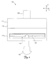
- Figure 2 is a side view of the measurement unit component of the testing system shown in Figure 1 .
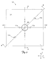
- Figure 3 is a top view of the measurement unit component of the testing system shown in Figure 2 .
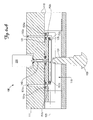
- Figure 4A is a cross-sectional side view of the measurement unit shown in Figure 3 taken along line 4-4 with the upper mounting plate in the open position spaced a distance away from the upper portion of the housing.
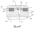
- Figure 4A 1 is an enlarged cross-sectional side view of the encircled inlet area of the gap in the measurement unit shown in Figure 4A .
- Figure 4A 2 is an enlarged cross-sectional side view of the encircled outlet area of the gap in the measurement unit shown in Figure 4A .
- Figure 4A 3 is an enlarged cross-sectional side view of the encircled sensor passageway area of the gap in the measurement unit shown in Figure 4A .
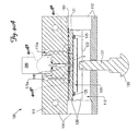
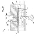
- Figure 4B is a cross-sectional side view of the measurement unit shown in Figure 3 taken along line 4-4 with the upper mounting plate in the closed position immediately adjacent the upper portion of the housing.
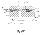
- Figure 4B 1 is an enlarged cross-sectional side view of the encircled inlet area of the gap in the measurement unit shown in Figure 4B .
- Figure 4B 2 is an enlarged cross-sectional side view of the encircled outlet area of the gap in the measurement unit shown in Figure 4B .
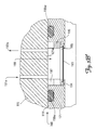
- Figure 4B 3 is an enlarged cross-sectional side view of the encircled sensor passageway area of the gap in the measurement unit shown in Figure 4B .
- Figure 5A is a cross-sectional side view of the measurement unit shown in Figure 3 taken along line 5-5 with the upper mounting plate in the open position spaced a distance away from the upper portion of the housing.
- Figure 5A 1 is an enlarged cross-sectional side view of the encircled humidity control window in the measurement unit shown in Figure 5A .
- Figure 5B is a cross-sectional side view of the measurement unit shown in Figure 3 taken along line 5-5 with the upper mounting plate in the closed position immediately adjacent the upper portion of the housing.
- Figure 5B 1 is an enlarged cross-sectional side view of the encircled humidity control window in the measurement unit shown in Figure 5B .
- Figure 6A is a cross-sectional side view of the measurement unit shown in Figure 3 taken along line 6-6 with the upper mounting plate in the open position spaced a distance away from the upper portion of the housing.
- Figure 6B is a cross-sectional side view of the measurement unit shown in Figure 3 taken along line 6-6 with the upper mounting plate in the closed position spaced a distance away from the upper portion of the housing.
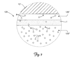
- Figure 7 is a grossly enlarged side view of the encircled portion of the testing chamber shown in Figure 3 depicting individual molecules of an analyte of interest on each side of a test film being tested with the measurement unit shown in Figure 4B .
- the invention is directed to a method for measuring the transmission rate of an analyte A through a film F .
- the method includes the steps of (i) separating a testing chamber 129 into a first or upper cell 129 1 and a second or lower cell 129 2 with a known area of a film F, (ii) flushing the first cell 129 1 with an inert gas to remove any target analyte A from the first cell 129 1 , (iii) introducing a gas (not shown) containing a known concentration of an analyte A into the lower cell 129 2 , (iv) sealing the upper cell 129 1 to gas flow (not shown) through the upper cell 129 1 , and (v) sensing any analyte A in the upper cell 129 1 with an analyte sensor 200 that consumes the analyte A at a rate greater than the rate at which the analyte A is passing through the film F, until a steady state rate of
- the film F can be a perforated or nonperforated film F, and can be porous or nonporous with respect to the target analyte A, so long as the analyte sensor 200 can consume the target analyte A at a rate greater than the rate at which the analyte A is passing through the film F.
- the analyte sensor 200 is preferably selected so that it consumes target analyte A at a rate that is at least ten times greater, preferably twenty times greater and most preferably 100 times greater, than the rate at which the target analyte A is likely to be transmitted through the film F.
- FIG. 1 An exemplary embodiment of a testing system 10 capable of measuring the transmission rate of an analyte A through a film F in accordance with the present invention is depicted in Figure 1 .
- a measurement unit 100 defines a testing chamber 129 sealingly divided by a film F to be tested into an upper cell 129 1 and a lower cell 129 2 .
- a source of an inert gas 21 communicates with the upper cell 129 1 via inlet conduit 41a and outlet conduit 41b for flushing the upper cell 129 1 prior to testing.
- Suitable inert gases include specifically, but not exclusively, nitrogen, argon, helium, krypton or a blend of nitrogen and hydrogen, etc.
- a source of test gas 22 containing a known concentration of an analyte A communicates with the lower cell 129 2 via inlet conduit 42a and outlet conduit 42b for continuously providing the lower cell 129 2 with test gas to ensure that the concentration of analyte A within the lower cell 129 2 remains constant throughout a test period.
- Shutoff valves 31a and 31b are provided in inlet conduit 41a and outlet conduit 41b respectively, for controlling the flow of inert gas through the upper cell 129 1 .
- shutoff valves 32a and 32b are provided in inlet conduit 42a and outlet conduit 42b respectively, for controlling the flow of gas through the lower cell 129 2 .
- An analyte sensor 200 for the target analyte A is placed in fluid communication with the upper cell 129 1 for sensing the presence of target anaylte A within the upper cell 129 1 .
- Typical target analytes include oxygen, carbon dioxide, carbon monoxide and water vapor.
- the analyte sensor 200 may be selected from any of the wide variety of commercially available consuming sensors capable of detecting and consuming the target analyte A, with electrochemical sensors generally preferred based upon the high sensitivity and low cost of such sensors and the fact that such sensors, when employed in the present invention, follow Faraday's Law - eliminating the need to calibrate the sensor.
- the analyte sensor 200 communicates via electrical leads 80 with a suitable central processing unit 50 equipped with electronic memory (not shown), and optionally but preferably attached to a monitor 60 and/or printer 70 for storing and reporting analyte A concentrations detected by the analyte sensor 200.
- a suitable central processing unit 50 equipped with electronic memory (not shown), and optionally but preferably attached to a monitor 60 and/or printer 70 for storing and reporting analyte A concentrations detected by the analyte sensor 200.
- a film F to be tested is "loaded" into the testing chamber 129 so as to sealingly separate the testing chamber 129 into an upper cell 129 1 and a lower cell 129 2 with a known area of the film F exposed to both cells 129 1 and 129 2 .
- Shutoff valves 31a and 31b are then opened to permit the flow of inert gas through the upper cell 129 1 for flushing analyte A from the upper cell 129 1 .
- the shutoff valves 31a and 31b are closed to seal-off the upper cell 129 1 from the surrounding environment.
- Shutoff valves 32a and 32b are then opened to permit the flow of gas containing a known concentration of analyte A into the lower cell 129 2 .
- analyte A within the upper cell 129 1 is then detected and recorded by the analyte sensor 200.
- the rate at which the analyte sensor 200 detects analyte A can be equated directly to the analyte transmission rate for the known "exposed" area of the film F.
- FIG. 2-6 An exemplary embodiment of a measurement unit 100 capable of quickly and accurately measuring the transmission rate of an analyte A through a film F in accordance with the present invention is depicted in Figures 2-6 .
- the measurement unit 100 includes (i) a housing 110, (ii) mounting plates 120, (iii) an actuator 130, (iv) a valve 140 for controlling fluid communication with an analyte sensor 200, (v) channels 150 in the housing 110 and mounting plates 120 for directing test gas (not shown) into a lower cell 129 2 in the mounting plates 120, and (vi) a flow control system (not collectively numbered) including flow control channels 170 and o-ring seals 180 for selectively opening and sealing closing an upper cell 129 1 in the mounting plates 120 to fluid flow.
- the measurement unit 100 optionally, but preferably, also includes a humidity control system 190.
- the housing 110 includes an upper section 111 and a lower section 112 that cooperatively define a retention chamber 119.
- upper and lower mounting plates 121 and 122 are retained within the retention chamber 119 defined by housing 110 with the upper surface 121u of the upper mounting plate 121 longitudinally y offset a distance from the lower surface 111i of the upper section 111 of the housing 110 so as to define a gap 160 therebetween.
- the upper and lower mounting plates 121 and 122 define a testing chamber 129 therebetween.
- An o-ring 125 encircling the testing chamber 129 is provided between the mounting plates 120.
- the testing chamber 129 can be sealingly divided into an upper cell 129 1 and a lower cell 129 2 by placement of a test film F between the mounting plates 120 overlaying the o-ring 125, and compressing the mounting plates 120 together so as to sealingly compress the entire periphery of the o-ring 125 between the mounting plates 120.
- the testing chamber 129 It is generally preferred to configure the testing chamber 129 to provide an upper cell 129 1 of about 1 cm 3 to about 3 cm 3 .
- An upper cell 129 1 larger than about 3 cm 3 is too slow to respond as molecules of analyte A within the upper cell 129 1 can be consumed and detected by the analyte sensor 200 only when the molecules enter the analyte sensor 200 and the upper cell 129 1 relies solely upon diffusion to move molecules within the upper cell 129 1 .
- An upper cell 129 1 smaller than about 1 cm 3 tends to cause areas of the film F to contact with the upper surface (not numbered) of the upper mounting plate 121 during the testing period, thereby introducing error into the test results as analyte A cannot readily pass through the film F into the upper cell 129 1 through these "covered" areas.
- the lower mounting plate 122 is mounted onto the distal end (unnumbered) of an actuator shaft 131 for longitudinally repositioning of the mounting plates 120 by an actuator 130 as between a lower or open position creating a longitudinally thicker gap 160 between the upper surface 121u of the upper mounting plate 121 and the lower surface 111i of the upper section 111 of the housing 110, as shown in Figures 4 (collectively 4A, 4A 1 , 4A 2 and 4A 3 ), and an upper or closed position creating a longitudinally thinner gap 160 between the upper surface 121u of the upper mounting plate 121 and the lower surface 111i of the upper section 111 of the housing 110, as shown in Figures 5 (collectively 5A, 5A 1 , 5A 2 and 5A 3 ).
- fluid flow into the lower cell 129 2 is provided by aligned inlet channels 151a, 151b and 151c in the upper section 111 of the housing 110, the upper mounting plate 121 and the lower mounting plate 122 respectively.
- fluid flow out from the lower cell 129 2 is provided by aligned outlet channels 152a, 152b and 152c in the upper section 111 of the housing 110, the upper mounting plate 121 and the lower mounting plate 122 respectively.
- a large diameter o-ring 151w is positioned within the gap 160 encircling the inlet channels 151a and 151b in the upper section 111 of the housing 110 and the upper mounting plate 121 for preventing testing gas from flowing throughout the gap 160.
- a large diameter o-ring 152w is positioned within the gap 160 encircling the outlet channels 152a and 152b in the upper section 111 of the housing 110 and the upper mounting plate 121 for preventing testing gas from flowing throughout the gap 160.
- the flow control system (not collectively numbered) includes (i) flow control channels and passageways 170 through the upper section 111 of the housing 110 and the upper mounting plate 121, and (ii) o-ring seals 180 of different diameters and different thicknesses positioned within the gap 160 and encircling the various channels and passageways 170.
- the flow control system provides a quick, simple and reliable method of opening and closing the upper cell 129 1 and the analyte sensor 200 to fluid flow at the appropriate times.
- fluid flow into the upper cell 129 1 is provided by laterally x and/or transversely z offset inlet channels 171a and 171b in the upper section 111 of the housing 110 and the upper mounting plate 121 respectively.
- fluid flow out from the upper cell 129 1 is provided by laterally x and/or transversely z offset outlet channels 172a and 172b in the upper section 111 of the housing 110 and the upper mounting plate 121 respectively.
- a small diameter o-ring 181v is positioned within the gap 160 encircling the inlet channel 171b in the upper mounting plate 121.
- a large diameter o-ring 181w is also positioned within the gap 160 for encircling both the inlet channel 171a in the upper section 111 of the housing 110 and the inlet channel 171b in the upper mounting plate 121 as well as fully encircling the small diameter o-ring 181v.
- a small diameter o-ring 182v is positioned within the gap 160 encircling the outlet channel 172b in the upper mounting plate 121, with a large diameter o-ring 182w positioned within the gap 160 and encircling both the outlet channel 172a in the upper section 111 of the housing 110 and the outlet channel 172b in the upper mounting plate 121 as well as encircling the small diameter o-ring 182v.
- the thickness or longitudinal y height of the large diameter o-rings 181w and 182w is selected so that these o-rings 181w and 182w are sealingly engaged within the gap 160 regardless of whether the mounting plates 120 are in the open or closed longitudinally y position so as to prevent fluid from flowing freely within the gap 160.
- the thickness or longitudinal y height of the smaller diameter o-rings 181v and 182v is selected so that these o-rings 181v and 182v are sealingly engaged within the gap 160 only when the mounting plates 120 are in the closed longitudinally y position.
- Such positioning of the larger ( 181w and 182w ) and smaller (181v and 182v) o-rings, in combination with the different thicknesses of the larger ( 181w and 182w ) and smaller ( 181v and 182v ) o-rings, permits the inlet ( 171a and 171b ) and outlet ( 172a and 172b ) channels to be simultaneously opened to fluid flow for flushing of the upper cell 129 1 prior to a testing period by longitudinally y moving the mounting plates 120 into the downward or open position as shown in Figures 4A, 4A 1 and 4A 2 , and simultaneously closed to fluid flow for sealing-off the upper cell 129 1 during a testing period by longitudinally y moving the mounting plates 120 into the upward or closed position as shown in Figures 4B, 4B 1 and 4B 2 .
- the analyte sensor 200 communicates with the upper cell 129 1 via longitudinally y aligned passageways 173a and 173b in the upper section 111 of the housing 110 and the upper mounting plate 121 respectively.
- a large diameter o-ring 183w is positioned within the gap 160 encircling both passageways 173a and 173b for ensuring that fluid diffusing into the analyte sensor 200 from the upper cell 129 1 is not contaminated by fluid from the gap 160.
- the passageway 173a should be closed at all times except during testing periods ( i . e ., only after the upper cell 129 1 has been flushed with an inert gas and sealed so that the only analyte A in the upper cell 129 1 is analyte A that has permeated through a test film F ).
- an expedient technique for providing such limited access to the analyte sensor 200 is to position a normally closed tire valve 140 within the passageway 173a, with the body 141 of the tire valve 140 sealingly wedged into the passageway 173a and the stem 142 of the tire valve 140 extending longitudinally y downward towards the gap 160.
- An upwardly extending pin 121n is provided on the upper mounting plate 121 for pressing longitudinally y upward against the valve stem 142 and thereby opening the valve 140 only when the mounting plates 120 are in the upper or closed position.
- a humidity control system 190 can be provided.
- a suitable humidity control system 190 is shown in Figures 5A, 5A 1 , 5B and 5B 1 .
- the humidity control system 190 include a pair of humidity control chambers 199 in the upper mounting plate 121 diametrically positioned relative to the analyte sensor 200 and in fluid communication with both the upper cell 129 1 and the gap 160.
- Inlet 191a and outlet 192a channels are provided in the upper section 111 of the housing 110 for placing each of the humidity control chambers 199 in fluid communication with a source of a gas (not shown) having a known humidity, typically 0% or 100% relative humidity.
- a large diameter o-ring 198w is positioned within the gap 160 encircling each of the humidity control chambers 199 and the corresponding set of inlet 191a and outlet 192a channels.
- a film 193 permeable to water vapor and impermeable to the target analyte A is provided over the opening of each humidity control chamber 199 into the upper cell 129 1 for purposes of allowing transpiration between the humidity control chamber 199 and the upper cell 129 1 without introducing extraneous analyte A into the upper cell 129 1 or allowing analyte A to escape from the upper cell 129 1 undetected.
- the selectively permeable film 193 can be sealingly held in position within each humidity control chamber 199 by an o-ring 194, washer 195, inset ring 196 and locking ring 197 as shown in Figures 5A 1 and 5B 1 .
- the mounting plates 120 are removed from the retention chamber 129 by activating the actuator 130 to lower the actuator shaft 131 into a removal position (not shown) where the o-ring seals 180 within the gap 160 no longer contact the upper section 111 of the housing 110, and sliding the mounting plates 120 out through an open side (not numbered) of the lower section 112 of the housing 110.
- the upper mounting plate 121 is then separated from the lower mounting plate 122, and a sample of the film F to be tested placed atop the lower mounting plate 122 over the test chamber 129 so as to fully engage the entire periphery of the o-ring 125 encircling the test chamber 129.
- the upper mounting plate 121 is then placed back atop the lower mounting plate 122 and secured to the lower mounting plate 122 so as to sealingly clamp the film F between the plates 121 and 122, thereby sealingly separating the testing chamber 129 into an upper cell 129 1 and a lower cell 129 2 with a known area of the film F exposed to both cells 129 1 and 129 2 .
- the "loaded" mounting plates 120 are then slid back into the retention chamber 119.
- the actuator 130 is activated to move the loaded mounting plates 120 into an "open" position wherein the larger diameter o-rings 181w, 182w, 183w and 198w located within the gap 160 sealingly engage the lower surface 111i of the upper section 111 of the housing 110 while the smaller diameter o-rings 181v and 182v within the gap 160 do not.
- the upper cell 129 1 is flushed with an inert gas to remove any target analyte A from the upper cell 129 1 by placing the inlet channel 171a in the upper section 111 of the housing 110 in fluid communication with a pressurized source of inert gas 21 and allowing the inert gas to flow sequentially through the inlet channel 171a in the upper section 111 of the housing 110, through that portion of the gap 160 surrounded by the larger diameter o-ring 181w, through the inlet channel 171b in the upper mounting plate 121, through the upper cell 129 1 , through the outlet channel 172b in the upper mounting plate 121, through that portion of the gap 160 surrounded by the larger diameter o-ring 182w, and out from the measurement unit 100 through the outlet channel 172a in the upper section 111 of the housing 110.
- the actuator 130 is activated to move the loaded mounting plates 120 into a "closed" position wherein both the larger diameter o-rings 181w, 182w, 183w and 198w and smaller diameter o-rings 181v and 182v within the gap 160 sealingly engage the lower surface 111i of the upper section 111 of the housing 110 so as to seal-off the upper cell 129 1 from the surrounding environment.
- movement of the loaded mounting plates 120 into the "closed” position also causes the pin 121n on the upper mounting plate 121 to engage the stem 142 on the valve 140 within the passageway 173a in the upper section 111 of the housing 110 so as to open the passageway 173a and thereby place the analyte sensor 200 in fluid communication with the upper cell 129 1 .
- the lower cell 129 2 is flushed with a test gas containing a known concentration of target analyte A and continuously supplied with "fresh” test gas throughout the testing period to ensure that the concentration of target analyte A within the lower cell 129 1 remains constant.
- Test gas is introduced into the lower cell 129 2 by placing the inlet channel 151a in the upper section 111 of the housing 110 in fluid communication with a pressurized source of test gas 22 and allowing the test gas to flow sequentially through the inlet channel 151a in the upper section 111 of the housing 110, through that portion of the gap 160 surrounded by the larger diameter o-ring 151w, through the inlet channel 151b in the upper mounting plate 121, through the inlet channel 151c in the lower mounting plate 122, through the lower cell 129 2 , through the outlet channel 152c in the lower mounting plate 122, through the outlet channel 152b in the upper mounting plate 121, through that portion of the gap 160 surrounded by the larger diameter o-ring 152w, and out from the measurement unit 100 through the outlet channel 152a in the upper section 111 of the housing 110.
- Target analyte A will permeate through the film F as the analyte A seeks to diffuse through the film F from a region of higher concentration ( i . e ., the lower cell 129 2 ) to a region of lower concentration ( i . e ., the upper cell 129 1 ). Since test gas continuously flows through the lower cell 129 2 the concentration of target analyte A in the region of higher concentration remains constant throughout the relevant test period. Similarly, since the analyte sensor 200 consumes target analyte A within the upper cell 129 1 faster that the target analyte A permeates through the film F, the concentration of target analyte A in the region of lower concentration also remains constant at essentially zero throughout the relevant test period.
- a 1.0 mil thick polyethylene terephthalate mylar film is placed between the mounting plates of the permeation testing system depicted in Figures 1-7 so as to provide a 50cm 2 area of the film exposed to both the upper and lower cells.
- Permeation testing is conducted in accordance with ASTM D3985 employing the following testing parameters: Gas In Upper Cell: Type: 100% N 2 RH: 10% Gas In Lower Cell: Type: 100% O 2 RH: 10% Testing Chamber Temp: 23°C Barometer: 742.3 mmHg
Landscapes
- Chemical & Material Sciences (AREA)
- Physics & Mathematics (AREA)
- General Health & Medical Sciences (AREA)
- General Physics & Mathematics (AREA)
- Health & Medical Sciences (AREA)
- Life Sciences & Earth Sciences (AREA)
- Analytical Chemistry (AREA)
- Biochemistry (AREA)
- Fluid Mechanics (AREA)
- Dispersion Chemistry (AREA)
- Immunology (AREA)
- Pathology (AREA)
- Sampling And Sample Adjustment (AREA)
- Investigating Or Analyzing Materials By The Use Of Electric Means (AREA)
- Investigating, Analyzing Materials By Fluorescence Or Luminescence (AREA)
- Investigating Or Analysing Materials By Optical Means (AREA)
Applications Claiming Priority (1)
| Application Number | Priority Date | Filing Date | Title |
|---|---|---|---|
| US12/114,471 US8691071B2 (en) | 2008-05-02 | 2008-05-02 | Coulometric analyte sensing instrument with an analyte-consuming sensor in a closed cell |
Publications (2)
| Publication Number | Publication Date |
|---|---|
| EP2113763A2 true EP2113763A2 (de) | 2009-11-04 |
| EP2113763A3 EP2113763A3 (de) | 2010-10-06 |
Family
ID=40758069
Family Applications (1)
| Application Number | Title | Priority Date | Filing Date |
|---|---|---|---|
| EP09005634A Withdrawn EP2113763A3 (de) | 2008-05-02 | 2009-04-22 | Coulometrisches Analytenerfassungsgerät mit einem Analytverbrauchssensor in einer geschlossenen Zelle |
Country Status (4)
| Country | Link |
|---|---|
| US (1) | US8691071B2 (de) |
| EP (1) | EP2113763A3 (de) |
| JP (1) | JP4954240B2 (de) |
| CN (1) | CN101598696B (de) |
Families Citing this family (1)
| Publication number | Priority date | Publication date | Assignee | Title |
|---|---|---|---|---|
| US12320745B2 (en) * | 2019-12-19 | 2025-06-03 | Radiometer Medical Aps | Porous membrane sensor assembly |
Citations (4)
| Publication number | Priority date | Publication date | Assignee | Title |
|---|---|---|---|---|
| JPS62119433A (ja) * | 1985-11-20 | 1987-05-30 | Fuji Electric Co Ltd | フイルムの水素透過係数測定装置 |
| US4973395A (en) | 1989-11-17 | 1990-11-27 | Modern Controls, Inc. | Humidified high sensitivity oxygen detector |
| US5053116A (en) | 1989-11-17 | 1991-10-01 | Modern Controls, Inc. | Device for humidifying gases without changing oxygen content |
| WO2000028300A1 (en) * | 1998-11-06 | 2000-05-18 | Valtion Teknillinen Tutkimuskeskus | Method and device for determining the permeability of a container or material to a gaseous substance |
Family Cites Families (26)
| Publication number | Priority date | Publication date | Assignee | Title |
|---|---|---|---|---|
| NO115503B (de) * | 1966-07-21 | 1968-10-14 | Sentralinst For Ind Forskning | |
| US3524341A (en) * | 1968-08-05 | 1970-08-18 | American Standard Inc | Pore determination of a porous member |
| US3590634A (en) * | 1969-05-05 | 1971-07-06 | Stanford Research Inst | Instrument for determining permeation rates through a membrane |
| US3618361A (en) * | 1970-03-02 | 1971-11-09 | Dohrmann Instr Co | Method and apparatus for determining gas permeability of film |
| JPS57145529A (en) * | 1981-03-02 | 1982-09-08 | Fuji Denki Sogo Kenkyusho Kk | Internal malfunction detector for oil-immersed electric device |
| JPS57145528A (en) * | 1981-03-02 | 1982-09-08 | Fuji Denki Sogo Kenkyusho Kk | Internal malfunction detector for oil-immersed electric device |
| JPS59144549A (ja) * | 1983-02-08 | 1984-08-18 | Aida Eng Ltd | 冷間鍛造用スラグの形状確認装置 |
| US4563249A (en) * | 1983-05-10 | 1986-01-07 | Orbisphere Corporation Wilmington, Succursale De Collonge-Bellerive | Electroanalytical method and sensor for hydrogen determination |
| US4656865A (en) * | 1985-09-09 | 1987-04-14 | The Dow Chemical Company | System for analyzing permeation of a gas or vapor through a film or membrane |
| GB2197080A (en) * | 1986-11-05 | 1988-05-11 | City Tech | Permeability/diffusion measurement |
| JP2601816B2 (ja) * | 1987-03-25 | 1997-04-16 | 三井石油化学工業 株式会社 | ガス透過試験機 |
| JPH0251043A (ja) * | 1988-08-11 | 1990-02-21 | Hamamatsu Photonics Kk | 隔体の気体透過試験方法 |
| US5131261A (en) * | 1988-08-26 | 1992-07-21 | The Dow Chemical Company | Permeation measurement device |
| US5265463A (en) * | 1992-07-24 | 1993-11-30 | Modern Controls, Inc. | Apparatus for measuring the transmission rate of volatile organic chemicals through a barrier material |
| US5390539A (en) * | 1992-09-25 | 1995-02-21 | Modern Controls, Inc. | Device for measuring the permeability of a membrane to water vapor |
| US5513515A (en) * | 1995-05-15 | 1996-05-07 | Modern Controls, Inc. | Method for measuring permeability of a material |
| US5591898A (en) * | 1995-10-12 | 1997-01-07 | Modern Controls, Inc. | Method for measuring material permeability characteristics |
| KR100213437B1 (ko) * | 1997-04-17 | 1999-08-02 | 윤종용 | 방진원단의 여과효율 측정장치 및 그 측정방법 |
| JPH1130579A (ja) * | 1997-05-16 | 1999-02-02 | Japan Pionics Co Ltd | 酸素拡散量測定方法、酸素拡散量測定装置および酸素拡散量で通気量を規定した発熱袋 |
| AU5554199A (en) * | 1998-08-11 | 2000-03-06 | Penn State Research Foundation, The | Rapid method to experimentally measure the gas permeability of micro-perforated films |
| US6009743A (en) * | 1998-08-24 | 2000-01-04 | Mocon, Inc. | Apparatus and method for online or offline measurement of vapor transmission through sheet materials |
| US6360588B1 (en) * | 1998-10-27 | 2002-03-26 | Edward Allan Ross | Materials and methods for the analysis of substances passing through a membrane |
| AU1725200A (en) * | 1998-11-16 | 2000-06-05 | California Institute Of Technology | Simultaneous determination of equilibrium and kinetic properties |
| US6766682B2 (en) * | 2001-10-19 | 2004-07-27 | Desert Cryogenics Llc | Precise measurement system for barrier materials |
| JP2003322583A (ja) * | 2002-02-26 | 2003-11-14 | Nippon Api Corp | リーク検査方法及び被検査物、並びに、ガス透過特性測定方法及び被測定物 |
| US7112443B2 (en) * | 2002-10-18 | 2006-09-26 | Symyx Technologies, Inc. | High throughput permeability testing of materials libraries |
-
2008
- 2008-05-02 US US12/114,471 patent/US8691071B2/en active Active
-
2009
- 2009-04-21 CN CN2009101368236A patent/CN101598696B/zh active Active
- 2009-04-22 EP EP09005634A patent/EP2113763A3/de not_active Withdrawn
- 2009-04-30 JP JP2009111238A patent/JP4954240B2/ja not_active Expired - Fee Related
Patent Citations (4)
| Publication number | Priority date | Publication date | Assignee | Title |
|---|---|---|---|---|
| JPS62119433A (ja) * | 1985-11-20 | 1987-05-30 | Fuji Electric Co Ltd | フイルムの水素透過係数測定装置 |
| US4973395A (en) | 1989-11-17 | 1990-11-27 | Modern Controls, Inc. | Humidified high sensitivity oxygen detector |
| US5053116A (en) | 1989-11-17 | 1991-10-01 | Modern Controls, Inc. | Device for humidifying gases without changing oxygen content |
| WO2000028300A1 (en) * | 1998-11-06 | 2000-05-18 | Valtion Teknillinen Tutkimuskeskus | Method and device for determining the permeability of a container or material to a gaseous substance |
Also Published As
| Publication number | Publication date |
|---|---|
| CN101598696B (zh) | 2013-09-25 |
| CN101598696A (zh) | 2009-12-09 |
| JP4954240B2 (ja) | 2012-06-13 |
| EP2113763A3 (de) | 2010-10-06 |
| US8691071B2 (en) | 2014-04-08 |
| US20100051481A1 (en) | 2010-03-04 |
| JP2009271072A (ja) | 2009-11-19 |
Similar Documents
| Publication | Publication Date | Title |
|---|---|---|
| US7993587B2 (en) | Humidity control system for the sensing cell of an analyte permeation testing instrument | |
| US6370940B2 (en) | Apparatus for determining concentration of a gas | |
| US6766682B2 (en) | Precise measurement system for barrier materials | |
| CN101074940B (zh) | 绝缘油中气体分析装置及绝缘油中气体的分析方法 | |
| US9945826B2 (en) | Functional test for gas sensors | |
| EP1992945B1 (de) | Selbstkalibrierender Gasspurensensor | |
| US20090320564A1 (en) | Method and Device for Measuring the Gas Permeability Through Films and Walls of Containers | |
| JP2010190751A (ja) | フィルム材料のガス透過度測定装置及びガス透過度測定方法 | |
| EP3605053B1 (de) | Vorrichtung zur messung ausgeatmeter luft | |
| JPS63304133A (ja) | 混合ガスを用いる分析計 | |
| US3718434A (en) | Apparatus and method for detecting gaseous contaminants | |
| JP5734109B2 (ja) | 測定装置および測定方法 | |
| EP2113763A2 (de) | Coulometrisches Analytenerfassungsgerät mit einem Analytverbrauchssensor in einer geschlossenen Zelle | |
| US8074683B1 (en) | Valve system for a coulometric analyte sensing instrument | |
| KR19980080105A (ko) | 반도체 처리챔버내의 오염물질 측정 방법 및 장치 | |
| JPH01227045A (ja) | 油入機器用ガス検出装置および油中ガス採取装置並びにガス検出方法 | |
| CN112147282A (zh) | 一种浓度传感器标定装置及标定方法 | |
| EP4328565B1 (de) | Analytenpermeationstestinstrument mit einer testprobenrandversiegelungseinfassung | |
| US20060120920A1 (en) | Hydrogen or helium sensor | |
| JP2954174B1 (ja) | 定電位電解式ガスセンサ | |
| Hale et al. | Gas analysis using a thermal conductivity method | |
| US7488449B2 (en) | Probe device for measuring ethanol concentrations in an aqueous solution | |
| WO2026059862A1 (en) | Calibration cartridge for use in calibrating ancillary sensors on a permeation analyzer | |
| JP3969187B2 (ja) | 溶存ガス計測計及び溶存ガス計測方法 | |
| CN117907530A (zh) | 气体检测装置及检测方法 |
Legal Events
| Date | Code | Title | Description |
|---|---|---|---|
| PUAI | Public reference made under article 153(3) epc to a published international application that has entered the european phase |
Free format text: ORIGINAL CODE: 0009012 |
|
| 17P | Request for examination filed |
Effective date: 20090519 |
|
| AK | Designated contracting states |
Kind code of ref document: A2 Designated state(s): AT BE BG CH CY CZ DE DK EE ES FI FR GB GR HR HU IE IS IT LI LT LU LV MC MK MT NL NO PL PT RO SE SI SK TR |
|
| PUAL | Search report despatched |
Free format text: ORIGINAL CODE: 0009013 |
|
| AK | Designated contracting states |
Kind code of ref document: A3 Designated state(s): AT BE BG CH CY CZ DE DK EE ES FI FR GB GR HR HU IE IS IT LI LT LU LV MC MK MT NL NO PL PT RO SE SI SK TR |
|
| AX | Request for extension of the european patent |
Extension state: AL BA RS |
|
| 17Q | First examination report despatched |
Effective date: 20110711 |
|
| STAA | Information on the status of an ep patent application or granted ep patent |
Free format text: STATUS: THE APPLICATION IS DEEMED TO BE WITHDRAWN |
|
| 18D | Application deemed to be withdrawn |
Effective date: 20181101 |