EP2113930A2 - Anneau d'antenne de stator - Google Patents
Anneau d'antenne de stator Download PDFInfo
- Publication number
- EP2113930A2 EP2113930A2 EP09005984A EP09005984A EP2113930A2 EP 2113930 A2 EP2113930 A2 EP 2113930A2 EP 09005984 A EP09005984 A EP 09005984A EP 09005984 A EP09005984 A EP 09005984A EP 2113930 A2 EP2113930 A2 EP 2113930A2
- Authority
- EP
- European Patent Office
- Prior art keywords
- ring
- statorantennenring
- sections
- wire winding
- section
- Prior art date
- Legal status (The legal status is an assumption and is not a legal conclusion. Google has not performed a legal analysis and makes no representation as to the accuracy of the status listed.)
- Granted
Links
Images
Classifications
-
- H—ELECTRICITY
- H01—ELECTRIC ELEMENTS
- H01F—MAGNETS; INDUCTANCES; TRANSFORMERS; SELECTION OF MATERIALS FOR THEIR MAGNETIC PROPERTIES
- H01F38/00—Adaptations of transformers or inductances for specific applications or functions
- H01F38/18—Rotary transformers
Definitions
- the invention relates to a stator antenna ring for an inductive telemetry system for measuring energy and measured value transmission according to the preamble of patent claim 1
- Such a telemetry system is from the DE 10 2005 040 794 A1 in which measured values are transmitted without contact from a rotor of a gas turbine to a stationary component and the energy required for this purpose is reversed.
- a support ring is arranged on the stationary device part, in which a stator coil with 10 turns of wire is fixed in isolation.
- the wire windings are mounted in a U-shaped groove and are outside of the Carrier ring connected to an alternator and a DC voltage source.
- the carrier ring is designed as a circulating iron core, so that the wire turns of the induction coil disposed therein must be arranged in isolation.
- the rotor is arranged in front of the carrier ring.
- a projecting annular web is flange-mounted, which dips coaxially into the inner region of the stator antenna ring and forms a rotor antenna ring.
- an induction coil is arranged as a rotor coil, which faces the stator coil in the form of a thin air gap.
- the rotor coil is connected to the measuring electronics mounted on the rotor so that the measuring signals and the measuring energy can be transmitted without contact during rotor operation.
- the invention is therefore based on the object to provide a Statorantennenring for an inductive telemetry system that can be used for torque measurement of feasible rotating measuring shafts and that can be easily installed without much installation effort in the measuring shaft system or is easily replaceable.
- the invention has the advantage that the radially divisible stator antenna ring mounted in a simple manner even when mounted Measuring shafts can be retrofitted or replaced without having to disassemble the measuring shaft.
- the embodiment with a receiving ring made of plastic material has the advantage that the induction coil relative to the stator does not have to be additionally insulated and is also very easy to produce.
- the invention with a single radially split wire turn has the additional advantage that it is very robust and reliable, in particular by the hidden entry into the plastic retainer ring.
- the embodiment with the dovetail groove on the inner circumferential surface of the carrier ring has the advantage that thereby the attachment of the induction coil to the stator without adhesive processes is easy to produce.
- stator made of a polyamide plastic also has the advantage that a very dimensionally stable and dimensionally accurate stator antenna ring can be produced. This additionally has the advantage that such a stator antenna ring does not have to be additionally insulated from the usually metallic stationary housing parts.
- Another particular embodiment of the invention in which the plastic carrier ring is mounted directly on a flat terminal housing, has the advantage that thus the Statorantennenring is directly screwed onto a stationary device part and thus at the same time the electronic connection and evaluation electronics is housed mechanically protected.
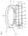
- the drawing shows a mounted on a terminal housing 2 Statorantennenring 1 for a telemetry system of a rotating torque-measuring device having a radially two-piece removable carrier ring 5 made of plastic, on the inner circumferential surface 8, a groove 9 is incorporated, in which a wire winding 10 of an induction coil. 3 is fixed, which is also divided disassembled, wherein the stator antenna ring 1 is fixed with its flattened base part 4 on the terminal housing 2.
- the plastic carrier ring 5 of the stator antenna ring 1 is circular and has an inner diameter of preferably about 200 mm and an outer diameter of about 240 mm. But there are also sizes with an inner diameter of 100 to 300 mm executable.
- the ring cross-section 14 is preferably rectangular or square, but may also have a rounded or a round shape.
- the plastic carrier ring 5 is preferably made of polyamide PA6, which acts simultaneously electrically insulating.
- a narrow groove 9 is recessed or milled approximately in the axial center of the inner circumferential surface 8, in which a single wire turn 10 of an induction coil 3 is fixed.
- the groove 9 is preferably milled as a dovetail groove into which the wire turn 10 is positively pressed by a Einklippvorgang and flush with the inner circumferential surface 8.
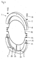
- Fig. 2 The design of the individual components of the stator antenna ring 1 without the connection housing 2 is in Fig. 2 the drawing shown in more detail. So shows Fig. 2 the drawing shows a radially two-part plastic carrier ring 5 as a carrier of the insulated introduced wire winding 10, which also according to the plastic ring parts consists of two radial sections 11, 12.
- the stator antenna ring 1 can be retrofitted even with a continuous rotatable measuring shaft, without having to dismantle the corrugated shaft section. Therefore, the plastic support ring 5 consists of a horizontal upper portion 6 and a horizontal lower portion 7 with a flattened foot part 4.
- Both horizonatlen sections 6, 7 have an angular range of 180 °, wherein the plastic support ring 5 could be composed of several and smaller sections.
- the two illustrated sections 6, 7 are fastened to each other on a horizontal line by means of two screw connections, each of which consists of a recessed in the lower section 7 threaded sleeve and with this each introduced through a hole in the lower section 6 screw 16.
- the stator ring 1 is screwed vertically horizontally on the underlying terminal housing 2 vertically.
- a cable feedthrough is provided in the connection housing 2 in the middle under the foot part 4, where the two connecting wires 17 of the split wire winding 10 are inserted and connected to the feed and evaluation electronics located therein.
- the sole wire winding 10 of the induction coil 3 is also divided into equal sections 11, 12 as the plastic carrier ring 5. So is in that Upper section 6 of the plastic carrier ring 5 also clamped an upper wire winding section 11 of 180 °, at the two ends of each a connecting shoe 13 is soldered.
- the wire winding 10 is made of a copper material, which is designed as a round or flat wire in order to be able to easily and reliably clip it into the dovetail groove 9.
- connection housing 2 the two connecting wires 17 of the induction coil 3 are connected to the feed and evaluation electronics located therein to ensure the inductive transmission.
- the terminal housing 2 is formed as a flat cuboid housing body, which does not protrude into the free inner cross section of the Statorantennenrings 1.
- two mounting plates 18 arranged alongside each other are also arranged, each having a bore, through which the stator antenna ring 1 can be screwed down to a stationary device part.
- stator antenna ring 1 For the function of the telemetry system, the stator antenna ring 1 must be coaxial with a rotor antenna ring that is rotatable in the interior leaving a small air gap between the two antenna parts. With such an antenna pre-alignment, carrier-frequency feed and measuring voltages of a rotatable torque measuring shaft can then be transmitted.
Landscapes
- Engineering & Computer Science (AREA)
- Power Engineering (AREA)
- Arrangements For Transmission Of Measured Signals (AREA)
Applications Claiming Priority (1)
| Application Number | Priority Date | Filing Date | Title |
|---|---|---|---|
| DE200810021775 DE102008021775B4 (de) | 2008-04-30 | 2008-04-30 | Statorantennenring |
Publications (3)
| Publication Number | Publication Date |
|---|---|
| EP2113930A2 true EP2113930A2 (fr) | 2009-11-04 |
| EP2113930A3 EP2113930A3 (fr) | 2013-06-26 |
| EP2113930B1 EP2113930B1 (fr) | 2019-03-27 |
Family
ID=40796302
Family Applications (1)
| Application Number | Title | Priority Date | Filing Date |
|---|---|---|---|
| EP09005984.1A Active EP2113930B1 (fr) | 2008-04-30 | 2009-04-30 | Anneau d'antenne de stator |
Country Status (2)
| Country | Link |
|---|---|
| EP (1) | EP2113930B1 (fr) |
| DE (1) | DE102008021775B4 (fr) |
Cited By (3)
| Publication number | Priority date | Publication date | Assignee | Title |
|---|---|---|---|---|
| CN112290191A (zh) * | 2020-11-21 | 2021-01-29 | 西安热工研究院有限公司 | 一种适用于叶片动应力/动频率测试的天线环装置 |
| JP2022024227A (ja) * | 2020-07-07 | 2022-02-09 | 日本航空電子工業株式会社 | 無線コネクタ着脱方法、ロボット装置、無線コネクタ及び無線コネクタユニット |
| EP4266485A1 (fr) * | 2022-04-19 | 2023-10-25 | Flender GmbH | Unité d'antenne de stator pour un dispositif de mesure |
Citations (1)
| Publication number | Priority date | Publication date | Assignee | Title |
|---|---|---|---|---|
| DE102005040794A1 (de) | 2004-09-09 | 2006-04-06 | Alstom Technology Ltd | Telemetriesystem für die Datenübermittlung, insbesondere zwischen dem rotierenden und dem stationären Teil einer Gasturbine |
Family Cites Families (2)
| Publication number | Priority date | Publication date | Assignee | Title |
|---|---|---|---|---|
| JPH01212131A (ja) * | 1988-02-19 | 1989-08-25 | Nippon Syst Kenkyusho:Kk | 分割コイル型同軸カプラを用いた伝送装置 |
| DE102004028595A1 (de) * | 2004-06-12 | 2005-12-29 | Daimlerchrysler Ag | Vorrichtung zum berührungslosen induktiven Übertragen von Energie und Daten und ein damit ausgestattetes Kraftfahrzeugmodul |
-
2008
- 2008-04-30 DE DE200810021775 patent/DE102008021775B4/de not_active Expired - Fee Related
-
2009
- 2009-04-30 EP EP09005984.1A patent/EP2113930B1/fr active Active
Patent Citations (1)
| Publication number | Priority date | Publication date | Assignee | Title |
|---|---|---|---|---|
| DE102005040794A1 (de) | 2004-09-09 | 2006-04-06 | Alstom Technology Ltd | Telemetriesystem für die Datenübermittlung, insbesondere zwischen dem rotierenden und dem stationären Teil einer Gasturbine |
Cited By (6)
| Publication number | Priority date | Publication date | Assignee | Title |
|---|---|---|---|---|
| JP2022024227A (ja) * | 2020-07-07 | 2022-02-09 | 日本航空電子工業株式会社 | 無線コネクタ着脱方法、ロボット装置、無線コネクタ及び無線コネクタユニット |
| US12206467B2 (en) | 2020-07-07 | 2025-01-21 | Japan Aviation Electronics Industry, Limited | Wireless connector attaching and detaching method, robot device, wireless connector, and wireless connector unit |
| CN112290191A (zh) * | 2020-11-21 | 2021-01-29 | 西安热工研究院有限公司 | 一种适用于叶片动应力/动频率测试的天线环装置 |
| EP4266485A1 (fr) * | 2022-04-19 | 2023-10-25 | Flender GmbH | Unité d'antenne de stator pour un dispositif de mesure |
| WO2023202874A1 (fr) * | 2022-04-19 | 2023-10-26 | Flender Gmbh | Ensemble antenne stator pour un dispositif de mesure |
| US12519205B2 (en) | 2022-04-19 | 2026-01-06 | Flender Gmbh | Stator antenna unit for a measuring arrangement |
Also Published As
| Publication number | Publication date |
|---|---|
| EP2113930A3 (fr) | 2013-06-26 |
| DE102008021775B4 (de) | 2012-06-28 |
| DE102008021775A1 (de) | 2009-11-05 |
| EP2113930B1 (fr) | 2019-03-27 |
Similar Documents
| Publication | Publication Date | Title |
|---|---|---|
| EP1927823B1 (fr) | Encodeur | |
| DE102011075548B4 (de) | Lager mit einer Energieerfassungseinheit, insbesondere Pendelrollen-Lager zur Lagerung einer Walze | |
| EP1927824B1 (fr) | Encodeur | |
| DE102014202719B4 (de) | Induktiver Drehübertrager für einen Elektromotor für ein Kraftfahrzeug sowie entsprechendes Kopplerteil | |
| EP3369160A1 (fr) | Entraînement direct d'essuie-glace | |
| EP2113930B1 (fr) | Anneau d'antenne de stator | |
| DE10161740B4 (de) | Schleifringübertrager | |
| DE102009040106A1 (de) | Schleifringvorrichtung | |
| DE102007020940B3 (de) | Vorrichtung zum Erkennen und Überwachen von Schäden bei Wälzlagern | |
| DE102005023182B4 (de) | Drehmomenterfassungsvorrichtung | |
| DE102018201537A1 (de) | Elektromotor | |
| WO2020126820A1 (fr) | Ensemble moteur comportant un module de détection | |
| DE102013224836A1 (de) | Hydrodynamische Maschine mit Messsystem | |
| DE102012016912A1 (de) | Platine zur Verwendung in einer elektrischen Maschine, insbesondere in einem Elektromotor, vorzugsweise einem Außenläufermotor, sowie elektrische Maschine mit einer solchen Platine | |
| EP4249855B1 (fr) | Capteur de rotation et procédé de fonctionnement d'un capteur de rotation | |
| DE102010009498A1 (de) | Drehsensor | |
| WO2009021904A1 (fr) | Machine électrique avec un dispositif de fixation d'un stator | |
| DE102009035368A1 (de) | Rotierende elektrische Vorrichtung für Fahrzeuge | |
| DE102016222925A1 (de) | Schleifringeinheit | |
| EP2875567B1 (fr) | Machine electrique et vehicule automobile a telle machine | |
| WO2015058762A1 (fr) | Palier à roulement doté d'un générateur électrique intégré en structure modulaire | |
| WO2009124849A1 (fr) | Machine électrique munie d'un dispositif permettant de fixer un stator | |
| DE102021204636A1 (de) | Prüfstand für ein Antriebsaggregat und Kontaktiervorrichtung zur elektrischen Kontaktierung einer Welle | |
| DE102019108981B4 (de) | Radsatzlager für ein Schienenfahrzeug und Verfahren zum Betrieb einer Sensorik eines Radsatzlagers | |
| DE10209415B4 (de) | Vorrichtung zur berührungslosen Hochfrequenzübertragung |
Legal Events
| Date | Code | Title | Description |
|---|---|---|---|
| PUAI | Public reference made under article 153(3) epc to a published international application that has entered the european phase |
Free format text: ORIGINAL CODE: 0009012 |
|
| AK | Designated contracting states |
Kind code of ref document: A2 Designated state(s): AT BE BG CH CY CZ DE DK EE ES FI FR GB GR HR HU IE IS IT LI LT LU LV MC MK MT NL NO PL PT RO SE SI SK TR |
|
| PUAL | Search report despatched |
Free format text: ORIGINAL CODE: 0009013 |
|
| AK | Designated contracting states |
Kind code of ref document: A3 Designated state(s): AT BE BG CH CY CZ DE DK EE ES FI FR GB GR HR HU IE IS IT LI LT LU LV MC MK MT NL NO PL PT RO SE SI SK TR |
|
| AX | Request for extension of the european patent |
Extension state: AL BA RS |
|
| RIC1 | Information provided on ipc code assigned before grant |
Ipc: H01F 38/18 20060101AFI20130522BHEP |
|
| 17P | Request for examination filed |
Effective date: 20131224 |
|
| RBV | Designated contracting states (corrected) |
Designated state(s): AT BE BG CH CY CZ DE DK EE ES FI FR GB GR HR HU IE IS IT LI LT LU LV MC MK MT NL NO PL PT RO SE SI SK TR |
|
| STAA | Information on the status of an ep patent application or granted ep patent |
Free format text: STATUS: EXAMINATION IS IN PROGRESS |
|
| 17Q | First examination report despatched |
Effective date: 20171107 |
|
| GRAP | Despatch of communication of intention to grant a patent |
Free format text: ORIGINAL CODE: EPIDOSNIGR1 |
|
| STAA | Information on the status of an ep patent application or granted ep patent |
Free format text: STATUS: GRANT OF PATENT IS INTENDED |
|
| INTG | Intention to grant announced |
Effective date: 20181001 |
|
| GRAS | Grant fee paid |
Free format text: ORIGINAL CODE: EPIDOSNIGR3 |
|
| GRAA | (expected) grant |
Free format text: ORIGINAL CODE: 0009210 |
|
| STAA | Information on the status of an ep patent application or granted ep patent |
Free format text: STATUS: THE PATENT HAS BEEN GRANTED |
|
| AK | Designated contracting states |
Kind code of ref document: B1 Designated state(s): AT BE BG CH CY CZ DE DK EE ES FI FR GB GR HR HU IE IS IT LI LT LU LV MC MK MT NL NO PL PT RO SE SI SK TR |
|
| REG | Reference to a national code |
Ref country code: GB Ref legal event code: FG4D Free format text: NOT ENGLISH |
|
| REG | Reference to a national code |
Ref country code: CH Ref legal event code: EP |
|
| REG | Reference to a national code |
Ref country code: AT Ref legal event code: REF Ref document number: 1114013 Country of ref document: AT Kind code of ref document: T Effective date: 20190415 |
|
| REG | Reference to a national code |
Ref country code: DE Ref legal event code: R082 Ref document number: 502009015673 Country of ref document: DE Representative=s name: STAUDTE, RALPH, DIPL.-ING., DE Ref country code: IE Ref legal event code: FG4D Free format text: LANGUAGE OF EP DOCUMENT: GERMAN |
|
| REG | Reference to a national code |
Ref country code: DE Ref legal event code: R096 Ref document number: 502009015673 Country of ref document: DE |
|
| PG25 | Lapsed in a contracting state [announced via postgrant information from national office to epo] |
Ref country code: SE Free format text: LAPSE BECAUSE OF FAILURE TO SUBMIT A TRANSLATION OF THE DESCRIPTION OR TO PAY THE FEE WITHIN THE PRESCRIBED TIME-LIMIT Effective date: 20190327 Ref country code: FI Free format text: LAPSE BECAUSE OF FAILURE TO SUBMIT A TRANSLATION OF THE DESCRIPTION OR TO PAY THE FEE WITHIN THE PRESCRIBED TIME-LIMIT Effective date: 20190327 Ref country code: NO Free format text: LAPSE BECAUSE OF FAILURE TO SUBMIT A TRANSLATION OF THE DESCRIPTION OR TO PAY THE FEE WITHIN THE PRESCRIBED TIME-LIMIT Effective date: 20190627 Ref country code: LT Free format text: LAPSE BECAUSE OF FAILURE TO SUBMIT A TRANSLATION OF THE DESCRIPTION OR TO PAY THE FEE WITHIN THE PRESCRIBED TIME-LIMIT Effective date: 20190327 |
|
| REG | Reference to a national code |
Ref country code: NL Ref legal event code: MP Effective date: 20190327 |
|
| PG25 | Lapsed in a contracting state [announced via postgrant information from national office to epo] |
Ref country code: HR Free format text: LAPSE BECAUSE OF FAILURE TO SUBMIT A TRANSLATION OF THE DESCRIPTION OR TO PAY THE FEE WITHIN THE PRESCRIBED TIME-LIMIT Effective date: 20190327 Ref country code: GR Free format text: LAPSE BECAUSE OF FAILURE TO SUBMIT A TRANSLATION OF THE DESCRIPTION OR TO PAY THE FEE WITHIN THE PRESCRIBED TIME-LIMIT Effective date: 20190628 Ref country code: LV Free format text: LAPSE BECAUSE OF FAILURE TO SUBMIT A TRANSLATION OF THE DESCRIPTION OR TO PAY THE FEE WITHIN THE PRESCRIBED TIME-LIMIT Effective date: 20190327 Ref country code: NL Free format text: LAPSE BECAUSE OF FAILURE TO SUBMIT A TRANSLATION OF THE DESCRIPTION OR TO PAY THE FEE WITHIN THE PRESCRIBED TIME-LIMIT Effective date: 20190327 Ref country code: BG Free format text: LAPSE BECAUSE OF FAILURE TO SUBMIT A TRANSLATION OF THE DESCRIPTION OR TO PAY THE FEE WITHIN THE PRESCRIBED TIME-LIMIT Effective date: 20190627 |
|
| PG25 | Lapsed in a contracting state [announced via postgrant information from national office to epo] |
Ref country code: IT Free format text: LAPSE BECAUSE OF FAILURE TO SUBMIT A TRANSLATION OF THE DESCRIPTION OR TO PAY THE FEE WITHIN THE PRESCRIBED TIME-LIMIT Effective date: 20190327 Ref country code: ES Free format text: LAPSE BECAUSE OF FAILURE TO SUBMIT A TRANSLATION OF THE DESCRIPTION OR TO PAY THE FEE WITHIN THE PRESCRIBED TIME-LIMIT Effective date: 20190327 Ref country code: RO Free format text: LAPSE BECAUSE OF FAILURE TO SUBMIT A TRANSLATION OF THE DESCRIPTION OR TO PAY THE FEE WITHIN THE PRESCRIBED TIME-LIMIT Effective date: 20190327 Ref country code: CZ Free format text: LAPSE BECAUSE OF FAILURE TO SUBMIT A TRANSLATION OF THE DESCRIPTION OR TO PAY THE FEE WITHIN THE PRESCRIBED TIME-LIMIT Effective date: 20190327 Ref country code: EE Free format text: LAPSE BECAUSE OF FAILURE TO SUBMIT A TRANSLATION OF THE DESCRIPTION OR TO PAY THE FEE WITHIN THE PRESCRIBED TIME-LIMIT Effective date: 20190327 Ref country code: PT Free format text: LAPSE BECAUSE OF FAILURE TO SUBMIT A TRANSLATION OF THE DESCRIPTION OR TO PAY THE FEE WITHIN THE PRESCRIBED TIME-LIMIT Effective date: 20190727 Ref country code: SK Free format text: LAPSE BECAUSE OF FAILURE TO SUBMIT A TRANSLATION OF THE DESCRIPTION OR TO PAY THE FEE WITHIN THE PRESCRIBED TIME-LIMIT Effective date: 20190327 |
|
| PG25 | Lapsed in a contracting state [announced via postgrant information from national office to epo] |
Ref country code: PL Free format text: LAPSE BECAUSE OF FAILURE TO SUBMIT A TRANSLATION OF THE DESCRIPTION OR TO PAY THE FEE WITHIN THE PRESCRIBED TIME-LIMIT Effective date: 20190327 |
|
| REG | Reference to a national code |
Ref country code: CH Ref legal event code: PL |
|
| REG | Reference to a national code |
Ref country code: BE Ref legal event code: MM Effective date: 20190430 |
|
| PG25 | Lapsed in a contracting state [announced via postgrant information from national office to epo] |
Ref country code: LU Free format text: LAPSE BECAUSE OF NON-PAYMENT OF DUE FEES Effective date: 20190430 Ref country code: IS Free format text: LAPSE BECAUSE OF FAILURE TO SUBMIT A TRANSLATION OF THE DESCRIPTION OR TO PAY THE FEE WITHIN THE PRESCRIBED TIME-LIMIT Effective date: 20190727 |
|
| REG | Reference to a national code |
Ref country code: DE Ref legal event code: R097 Ref document number: 502009015673 Country of ref document: DE |
|
| PG25 | Lapsed in a contracting state [announced via postgrant information from national office to epo] |
Ref country code: MC Free format text: LAPSE BECAUSE OF FAILURE TO SUBMIT A TRANSLATION OF THE DESCRIPTION OR TO PAY THE FEE WITHIN THE PRESCRIBED TIME-LIMIT Effective date: 20190327 Ref country code: CH Free format text: LAPSE BECAUSE OF NON-PAYMENT OF DUE FEES Effective date: 20190430 Ref country code: LI Free format text: LAPSE BECAUSE OF NON-PAYMENT OF DUE FEES Effective date: 20190430 Ref country code: DK Free format text: LAPSE BECAUSE OF FAILURE TO SUBMIT A TRANSLATION OF THE DESCRIPTION OR TO PAY THE FEE WITHIN THE PRESCRIBED TIME-LIMIT Effective date: 20190327 |
|
| PLBE | No opposition filed within time limit |
Free format text: ORIGINAL CODE: 0009261 |
|
| STAA | Information on the status of an ep patent application or granted ep patent |
Free format text: STATUS: NO OPPOSITION FILED WITHIN TIME LIMIT |
|
| GBPC | Gb: european patent ceased through non-payment of renewal fee |
Effective date: 20190627 |
|
| PG25 | Lapsed in a contracting state [announced via postgrant information from national office to epo] |
Ref country code: SI Free format text: LAPSE BECAUSE OF FAILURE TO SUBMIT A TRANSLATION OF THE DESCRIPTION OR TO PAY THE FEE WITHIN THE PRESCRIBED TIME-LIMIT Effective date: 20190327 Ref country code: BE Free format text: LAPSE BECAUSE OF NON-PAYMENT OF DUE FEES Effective date: 20190430 |
|
| 26N | No opposition filed |
Effective date: 20200103 |
|
| PG25 | Lapsed in a contracting state [announced via postgrant information from national office to epo] |
Ref country code: TR Free format text: LAPSE BECAUSE OF FAILURE TO SUBMIT A TRANSLATION OF THE DESCRIPTION OR TO PAY THE FEE WITHIN THE PRESCRIBED TIME-LIMIT Effective date: 20190327 |
|
| PG25 | Lapsed in a contracting state [announced via postgrant information from national office to epo] |
Ref country code: GB Free format text: LAPSE BECAUSE OF NON-PAYMENT OF DUE FEES Effective date: 20190627 Ref country code: IE Free format text: LAPSE BECAUSE OF NON-PAYMENT OF DUE FEES Effective date: 20190430 |
|
| PG25 | Lapsed in a contracting state [announced via postgrant information from national office to epo] |
Ref country code: FR Free format text: LAPSE BECAUSE OF NON-PAYMENT OF DUE FEES Effective date: 20190527 |
|
| REG | Reference to a national code |
Ref country code: AT Ref legal event code: MM01 Ref document number: 1114013 Country of ref document: AT Kind code of ref document: T Effective date: 20190430 |
|
| PG25 | Lapsed in a contracting state [announced via postgrant information from national office to epo] |
Ref country code: AT Free format text: LAPSE BECAUSE OF NON-PAYMENT OF DUE FEES Effective date: 20190430 |
|
| REG | Reference to a national code |
Ref country code: DE Ref legal event code: R082 Ref document number: 502009015673 Country of ref document: DE Representative=s name: STAUDTE, RALPH, DIPL.-ING., DE Ref country code: DE Ref legal event code: R081 Ref document number: 502009015673 Country of ref document: DE Owner name: HOTTINGER BRUEEL & KJAER GMBH, DE Free format text: FORMER OWNER: HOTTINGER BALDWIN MESSTECHNIK GMBH, 64293 DARMSTADT, DE |
|
| PG25 | Lapsed in a contracting state [announced via postgrant information from national office to epo] |
Ref country code: CY Free format text: LAPSE BECAUSE OF FAILURE TO SUBMIT A TRANSLATION OF THE DESCRIPTION OR TO PAY THE FEE WITHIN THE PRESCRIBED TIME-LIMIT Effective date: 20190327 |
|
| PG25 | Lapsed in a contracting state [announced via postgrant information from national office to epo] |
Ref country code: HU Free format text: LAPSE BECAUSE OF FAILURE TO SUBMIT A TRANSLATION OF THE DESCRIPTION OR TO PAY THE FEE WITHIN THE PRESCRIBED TIME-LIMIT; INVALID AB INITIO Effective date: 20090430 Ref country code: MT Free format text: LAPSE BECAUSE OF FAILURE TO SUBMIT A TRANSLATION OF THE DESCRIPTION OR TO PAY THE FEE WITHIN THE PRESCRIBED TIME-LIMIT Effective date: 20190327 |
|
| PG25 | Lapsed in a contracting state [announced via postgrant information from national office to epo] |
Ref country code: MK Free format text: LAPSE BECAUSE OF FAILURE TO SUBMIT A TRANSLATION OF THE DESCRIPTION OR TO PAY THE FEE WITHIN THE PRESCRIBED TIME-LIMIT Effective date: 20190327 |
|
| P01 | Opt-out of the competence of the unified patent court (upc) registered |
Effective date: 20230606 |
|
| PGFP | Annual fee paid to national office [announced via postgrant information from national office to epo] |
Ref country code: DE Payment date: 20250319 Year of fee payment: 17 |