EP4266485A1 - Unité d'antenne de stator pour un dispositif de mesure - Google Patents
Unité d'antenne de stator pour un dispositif de mesure Download PDFInfo
- Publication number
- EP4266485A1 EP4266485A1 EP22168811.2A EP22168811A EP4266485A1 EP 4266485 A1 EP4266485 A1 EP 4266485A1 EP 22168811 A EP22168811 A EP 22168811A EP 4266485 A1 EP4266485 A1 EP 4266485A1
- Authority
- EP
- European Patent Office
- Prior art keywords
- antenna holder
- antenna
- unit
- stator
- signal receiver
- Prior art date
- Legal status (The legal status is an assumption and is not a legal conclusion. Google has not performed a legal analysis and makes no representation as to the accuracy of the status listed.)
- Withdrawn
Links
Images





Classifications
-
- H—ELECTRICITY
- H01—ELECTRIC ELEMENTS
- H01Q—ANTENNAS, i.e. RADIO AERIALS
- H01Q1/00—Details of, or arrangements associated with, antennas
- H01Q1/12—Supports; Mounting means
-
- H—ELECTRICITY
- H01—ELECTRIC ELEMENTS
- H01Q—ANTENNAS, i.e. RADIO AERIALS
- H01Q1/00—Details of, or arrangements associated with, antennas
- H01Q1/12—Supports; Mounting means
- H01Q1/22—Supports; Mounting means by structural association with other equipment or articles
-
- F—MECHANICAL ENGINEERING; LIGHTING; HEATING; WEAPONS; BLASTING
- F16—ENGINEERING ELEMENTS AND UNITS; GENERAL MEASURES FOR PRODUCING AND MAINTAINING EFFECTIVE FUNCTIONING OF MACHINES OR INSTALLATIONS; THERMAL INSULATION IN GENERAL
- F16H—GEARING
- F16H57/00—General details of gearing
- F16H57/02—Gearboxes; Mounting gearing therein
- F16H57/021—Shaft support structures, e.g. partition walls, bearing eyes, casing walls or covers with bearings
-
- H—ELECTRICITY
- H01—ELECTRIC ELEMENTS
- H01Q—ANTENNAS, i.e. RADIO AERIALS
- H01Q7/00—Loop antennas with a substantially uniform current distribution around the loop and having a directional radiation pattern in a plane perpendicular to the plane of the loop
-
- F—MECHANICAL ENGINEERING; LIGHTING; HEATING; WEAPONS; BLASTING
- F16—ENGINEERING ELEMENTS AND UNITS; GENERAL MEASURES FOR PRODUCING AND MAINTAINING EFFECTIVE FUNCTIONING OF MACHINES OR INSTALLATIONS; THERMAL INSULATION IN GENERAL
- F16H—GEARING
- F16H57/00—General details of gearing
- F16H57/02—Gearboxes; Mounting gearing therein
- F16H2057/02026—Connection of auxiliaries with a gear case; Mounting of auxiliaries on the gearbox
-
- F—MECHANICAL ENGINEERING; LIGHTING; HEATING; WEAPONS; BLASTING
- F16—ENGINEERING ELEMENTS AND UNITS; GENERAL MEASURES FOR PRODUCING AND MAINTAINING EFFECTIVE FUNCTIONING OF MACHINES OR INSTALLATIONS; THERMAL INSULATION IN GENERAL
- F16H—GEARING
- F16H57/00—General details of gearing
- F16H57/02—Gearboxes; Mounting gearing therein
- F16H2057/02039—Gearboxes for particular applications
- F16H2057/02069—Gearboxes for particular applications for industrial applications
- F16H2057/02073—Reduction gearboxes for industry
-
- G—PHYSICS
- G01—MEASURING; TESTING
- G01M—TESTING STATIC OR DYNAMIC BALANCE OF MACHINES OR STRUCTURES; TESTING OF STRUCTURES OR APPARATUS, NOT OTHERWISE PROVIDED FOR
- G01M13/00—Testing of machine parts
- G01M13/02—Gearings; Transmission mechanisms
-
- H—ELECTRICITY
- H01—ELECTRIC ELEMENTS
- H01F—MAGNETS; INDUCTANCES; TRANSFORMERS; SELECTION OF MATERIALS FOR THEIR MAGNETIC PROPERTIES
- H01F38/00—Adaptations of transformers or inductances for specific applications or functions
- H01F38/18—Rotary transformers
Definitions
- the invention relates to a stator antenna unit for mounting in a transmission housing structure and for interaction with a rotor element arranged in the transmission housing structure on a transmission component and describing an axial direction, with an annular antenna holder, a signal receiver running circumferentially on the antenna holder and a signal receiver connected to the signal receiver electrically and in terms of signaling technology connected signal evaluation unit.
- the antenna unit is electrically and signally connected to an evaluation unit, with the evaluation unit in any case outside the Gear housing structure arranged because it is not exposed to the conditions prevailing inside the gear housing structure. However, the evaluation unit is then exposed to the environmental conditions, which not least include mechanical influences from handling devices. There is a constant need to improve such sensor components with regard to their arrangement and their interaction.
- stator antenna unit with the features of claim 1.
- Preferred embodiments are specified in the subclaims and the following description, which can each represent an aspect of the invention individually or in combination. If a feature is shown in combination with another feature, this only serves to simplify the presentation of the invention and is in no way intended to mean that this feature cannot be a further development of the invention without the other feature.
- One embodiment relates to a stator antenna unit for mounting in a transmission housing structure and for interaction with a rotor element arranged in the transmission housing structure on a transmission component and describing an axial direction, comprising an annular antenna holder, a signal receiver running circumferentially on the antenna holder, and an electrically and signally connected signal receiver to the signal receiver and a signal evaluation unit attached to the antenna holder, the antenna holder being designed in several parts and being pivotable via a hinge between a circumferentially closed position and a circumferentially open position.
- the gearbox structure can be a gearbox that can be constructed in several parts. For example, two housing halves placed against each other via respective connecting flanges can be provided. A main housing part can also be provided, against which a housing cover is placed in order to obtain a closed gear housing. The housing halves or the housing part can be trough-shaped.
- the gearbox housing can form respective shaft bushings designed as bores for one or more drive shafts and one or more output shafts. A bearing for supporting one of the shafts can be accommodated in a bore.
- An oil reservoir for receiving at least part of an oil filling can be provided in a lower region of the transmission housing.
- a transmission component is, for example, a rotating component that describes an axial direction through its axis of rotation.
- a component can be a drive or output side gear shaft, a roller or plain bearing or even a toothed element.
- the rotor element can be, for example, a coil with a ferrite core arranged on a transmission shaft.
- the annular antenna holder is arranged circumferentially around the rotor element in order to interact with it.
- the antenna holder is expediently held and positioned relative to the transmission housing structure. In particular, positioning can include radial and axial tolerance compensation.
- the term “annular” can also be referred to as “circular” unless understood in a strictly geometric sense.
- an inner peripheral surface of the antenna holder is geometrically circular and is arranged in the area of this inner peripheral surface of the signal receiver running circumferentially on the antenna holder.
- the signal receiver is preferably embedded in the inner circumferential surface, in particular in a circumferential groove or in a channel.
- the groove or channel can be in Viewed in cross section, it can be designed to be dovetail-shaped so that the signal receiver can be easily clicked in and is held in a form-fitting manner relative to the antenna holder.
- a rectangular, circumferential groove with several cams distributed over the circumference can also be provided, behind which the signal receiver can be clamped.
- the signal receiver can also be inserted into a rectangular, circumferential groove and then glued in.
- the antenna holder can be manufactured using a 3D printing process. Alternatively, it can be manufactured using injection molding, vacuum casting or other casting processes. It is also conceivable that it is manufactured using a conventional, machining process.
- the evaluation unit contains the stator electronics.
- An induction field acting on the rotor element is generated via the evaluation unit using an alternating current. This supplies the rotor element with voltage.
- the evaluation unit modulates the induction field via the alternating current, so that the respective measurement data of the state variables to be recorded can be transmitted via modulation.
- the signal receiver preferably comprises a copper cable or a copper tape, which is pre-insulated or laminated, so that insulation and covering steps are not required during assembly.
- the copper cable or copper tape can be fixed at the correct distance above the rotor element in both the axial and radial directions using the antenna holder.
- the copper cable or copper tape is expediently laid as a loop.
- the antenna holder ensures that the loop forms a closed circuit to avoid power interruptions or communication errors and is neither compressed, extended, nor impaired in any other way during an operating situation.
- the loop is integrated via the antenna holder in such a way that no mechanical forces can cause geometry changes or damage, and axial and radial position changes are excluded.
- the fact that the evaluation unit is attached to the antenna holder can ensure that the evaluation unit and the loop of the signal receiver can be positioned close to one another.
- the stator antenna unit is expediently grounded.
- a connection to the transmission housing structure is provided, which assumes ground potential.
- a grounding strap can be placed in a channel by the evaluation unit.
- a metal sheet which is connected to the transmission housing structure via a screw, presses on the end of the grounding strap.
- a spring underneath the screw head can generate a permanently defined contact force.
- Other connection options for the ground strap are also possible.
- the antenna holder In the two-part design of the antenna holder, it can be composed of two or more essentially equal parts. It is intended that one of these parts carries the evaluation unit.
- the two-part design has the particular advantage that the stator antenna unit can be mounted around a gear shaft that has already been mounted in a gear housing structure.
- the stator antenna unit can also be installed as part of retrofitting gearboxes that are already in operation.
- the two-part antenna holder can be opened or unfolded using the hinge in order to be guided or slipped over the transmission shaft. The antenna holder can then be closed again. A latching mechanism can be provided for this.
- the antenna holder is designed in two parts via two half-shell elements and the two half-shell elements are connected to one another via the hinge and can be pivoted between the circumferentially closed position and the circumferentially open position.
- each half-shell element essentially describes 180° of a complete circumference.
- three shell elements it is also possible for three shell elements to be provided, which are then pivotally connected to one another via two hinges. For certain applications it is also conceivable that more than three shell elements are connected to one another in an articulated manner.
- the stator antenna unit described here can be completely integrated with its components in a gearbox and can be used universally, as it can be used as a series solution for different gearbox series through pure scaling. Construction effort is reduced to a minimum.
- the assembly of the pre-assembled stator antenna unit can be easily integrated into the typical assembly process of the gearbox.
- the stator antenna unit provides a production-ready option with which telemetry can be used for measuring systems in transmission series.
- the complete integration of the stator antenna unit leads to a greatly increased reliability of the telemetry.
- a stop arranged on the outside circumference of the antenna holder limits pivoting from the closed position into the open position.
- the stop can be arranged on the outside of the hinge.
- the stop and the limitation of the pivoting movement ensure that the signal receiver, for example the copper cable or copper tape, is not damaged when the antenna holder is pivoted into the open position.
- the stop limits pivoting of the two half-shell elements to approximately 70°. This opening angle allows the antenna holder to be placed over the outer diameter of a transmission shaft.
- the signal receiver is guided in the area of the hinge, starting from the circumferential course in the direction of the signal evaluation unit.
- the signal receiver can in particular be guided in such a way that, starting from the circumferential course, the signal receiver is first guided past the hinge in the radial direction and then guided again in the circumferential direction or also in the tangential direction to the evaluation unit.
- the signal receiver which is preferably designed as a copper cable or copper strip, is conductively connected to the evaluation unit, for which purpose a soldered connection is preferably used. In order to ensure accessibility to the evaluation unit for attaching the solder connection, there is an access opening provided in the antenna holder.
- the configuration in which the evaluation unit is arranged directly on the antenna holder can advantageously ensure that a length of the signal receiver from the hinge to a connection to the evaluation unit does not exceed a distance of 400mm.
- the antenna holder in the area of the hinge on an axial side forms a recess extending up to an axis of rotation of the hinge for receiving the signal receiver guided in the direction of the signal evaluation unit.
- the recess ensures that when the antenna holder is swung open into the open position, the signal receiver, for example the copper cable or copper tape, is not elongated or compressed.
- a preferred embodiment also provides that two wire ends of the signal receiver are guided radially outwards at a separation point of the antenna holder that is opposite the hinge, preferably diametrically, starting from the circumferential course.
- the separation point is the area in which both half-shell elements meet in the closed position of the antenna holder and in which they move apart when opened.
- the latching mechanism can be arranged at the separation point.
- the signal receiver has two wire ends that are not initially connected to one another and are only conductively connected to one another after assembly in a transmission structure.
- the two wire ends expediently lie directly or largely close to one another in the area of the separation point in the closed position of the antenna holder, so that both wire ends can easily be connected at a later point in time.
- the two wire ends can open into a funnel formed on the outside circumference of the antenna holder.
- simple measures can be used to ensure that the two wire ends are conductive to one another via soldering in the closed position and at least in an operating state of the antenna holder are connected.
- the funnel advantageously facilitates the application of a solder and the targeted feeding to the two wire ends.
- the signal evaluation unit is accommodated in a receiving pocket of the antenna holder, cast with a synthetic resin. This ensures that the evaluation unit is securely and firmly attached to the antenna holder.
- the evaluation unit is preferably accommodated in the receiving pocket via a positive coding. After inserting the evaluation unit, it is cast with synthetic resin.
- At least one axially directed opening is provided in the antenna holder. This ensures that the stator antenna unit can be arranged, for example, axially in front of a bearing and that an oil flow from and to the bearing is ensured by the at least one axial breakthrough. An oil jam is thus avoided.
- a transmission with a transmission housing, at least one shaft rotatably mounted in the transmission housing via a roller bearing, the roller bearing being seated in a housing bore of the transmission housing and at least one stator antenna unit surrounding the shaft being provided as described above.
- the antenna holder projects into the housing bore with an at least partially circumferential collar.
- the collar can partially cover approximately 200° of a total circumference.
- the antenna holder sits in the housing bore in a circumferential supporting manner and rests axially against a bearing ring of the rolling bearing.
- the axial support takes place via a bushing seated in the housing bore.
- the circumferential support enables the antenna holder to be positioned in the radial direction in relation to the gearbox housing.
- a bearing ring of the rolling bearing which can be the outer bearing ring, for example, positioning of the antenna holder in the axial direction with respect to the gearbox housing is achieved.
- the advantage here is that the telemetry is largely located in the immediate vicinity of the storage, which increases the usability of the telemetry. Many different relevant measurements can be recorded and transmitted using telemetry. Measured variables include, for example, torque, axial forces, bending forces, tooth root stresses, temperatures on the bearing inner ring, and stresses near the notch.
- a drive train comprising a first shaft designed as a drive shaft, which is torque-transmittingly coupled via a gear to a second shaft designed as an output shaft, the gear being designed as previously described.
- the task is solved by an industrial application comprising a drive unit which is connected to an output unit via a transmission to transmit torque, the transmission being designed as described above.
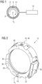
- the Fig. 1 shows purely schematically a basic structure of a measuring arrangement 2.
- a rotor element 8 provided with a coil and ferrite core 9 is surrounded by an antenna holder 12, on which a signal receiver 14 is arranged circumferentially.
- the signal receiver 14 forms a loop on the antenna holder 12.
- the signal receiver 14 continues to a signal evaluation unit 16.
- the signal evaluation unit 16 is attached to the antenna holder 12, which is in the Figure 1 is not shown.
- the signal receiver 16, the antenna holder 12 and the evaluation unit 16 are part of a stator antenna unit 10, which functionally forms the counterpart to the rotor element 8 with coil and ferrite core 9.
- the signal receiver 14 can in this case be designed as a copper wire or copper strip and can be provided with enveloping insulation.
- the rotor element 8 is rotatable about an axis of rotation A D , so that the axis of rotation A D describes an axial direction D. A possible direction of rotation of the rotor element 8 is symbolized by the curved arrow.
- the rotor element 8 can be, for example, a transmission shaft.
- the Figure 2 shows the antenna holder 12 of a stator antenna unit 10 as a detail in a perspective view.
- the antenna holder 12 is essentially ring-shaped formed and is composed of two half-shell elements 20, 22 in two parts. Both half-shell elements 20, 22 are pivotally connected to one another at one end via a hinge 18 and are connected to one another via a separating point 32 at their other ends, which are essentially diametrically opposite to the hinge 18. Via the separation point 32, the respective ends of the half-shell elements 20, 22 can be released from one another after releasing a locking mechanism 46, so that the half-shell elements 20, 22 can be pivoted relative to one another about a pivot axis As of the hinge 18.
- the antenna holder 12 forms a receiving pocket 36 on one of the half-shell elements 20, 22 for receiving and holding the evaluation unit 16.
- the evaluation unit is in the Figure 2 not shown.
- the antenna holder 12 also has several axially directed and circumferentially distributed openings 38 through which oil can flow, for example from and to a bearing, during operation.
- a circumferential channel 40 is formed on an inner peripheral surface of the antenna holder 12, which serves to accommodate the signal receiver 14, which is in the Figure 2 however, is not shown.
- the channel 40 can be designed as a groove and, viewed in cross section, can be designed to be dovetail-shaped, so that the signal receiver 14 can be easily clicked in and is held in a form-fitting manner relative to the antenna holder 12.
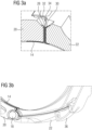
- the Figures 3a) and 3b ) show details of the course of the signal receiver 14 in the area of the separation point 32 - Figure 3a ) - and in the area of the hinge 18 up to the receiving pocket 36 - Figure 3b ).
- the signal receiver 14 is guided radially outwards at the separation point 32, starting from the circumferential course in the channel 40, and two wire ends 28, 30 of the signal receiver 14 open into a funnel 34 formed on the outside circumference of the antenna holder 12. Via the funnel 34, it is easily possible to conductively connect the two wire ends 28, 30 to one another via soldering in the closed position and at least in an operating state of the antenna holder 12. Soldering is not shown here.
- the signal receiver 14 is guided past the hinge 18 in the radial direction and then again in the circumferential direction or in the tangential direction to the receiving pocket 36 to the evaluation unit 16 - not shown.
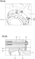
- the Figure 4a shows a further detail of the separation point 32.
- the separation point 32 includes a latching mechanism 46 which is effective between the two half-shell elements 20, 22 so that they do not unintentionally move into the open position.
- the latching mechanism 46 can be unlocked by inserting a pin 48, so that the two half-shell elements 20, 22 can then be pivoted into the open position.
- the Figure 4b shows a view of the area of the antenna holder 12, in which the signal receiver 14 is guided by the hinge 18 to the evaluation unit 16 located in the receiving pocket 36.
- the signal receiver 14 runs between the hinge 18 and the receiving pocket in a guide channel 42.
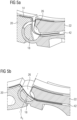
- the Figures 5a) and 5b ) show detailed views of the antenna holder 12 and the signal receiver 14 in the area of the hinge 18.
- the Figure 5a ) shows the antenna holder 12 in the closed position, in which the two half-shell elements 20, 22 form a ring over the closed separation point 32 - not shown.
- the Figure 5b ) shows the antenna holder 12 in the open position, in which the half-shell elements 20, 22 are pivoted towards each other via the hinge 18.
- a recess 26 is formed up to the axis of rotation A s of the hinge 18, for receiving the signal receiver 14 guided in the direction of the signal evaluation unit 16.
- the Figure 6a shows a further detail of the antenna holder 12, namely a stop 24, which limits pivoting from the closed position into the open position of the two half-shell elements 20, 22.
- the stop 24 is arranged on the outside circumference in the area of the hinge 18.
- the Figure 6b shows the two half-shell elements 20, 22 of the antenna holder 12 in the open position, in which further swinging open is prevented by the stop 24.
- a value of an angle by which both half-shell elements 20, 22 in the hinge 18 can be pivoted relative to one another into the open position can be, for example, 70°.
- the Figures 7a) and 7b ) show further details of the evaluation unit 16 located in the receiving pocket 36.
- the evaluation unit 16 has a positive coding 44 for clear positioning in the receiving pocket 36.
- the Figures 8a) and 8b ) show the stator antenna unit 10 in an assembly with a gear housing structure 4.
- the gear housing structure 4 is formed in the present case by a housing side wall.
- a bearing bore 50 is formed in the housing side wall 4, in which a rolling bearing 52 is seated in a known manner, see Figure 8b ).
- a transmission shaft that is rotatably held in the rolling bearing 52 relative to the transmission housing structure 4 is not shown here.
- the stator antenna unit 10 is held against the housing side wall 4 from an inside.
- the antenna holder 12 forms a circumferential or partially circumferential collar 54 which projects into the bearing bore 50.
- the antenna holder 12 is supported circumferentially in the bearing bore 50 via the collar 54 and rests axially against the bearing outer ring 56 of the rolling bearing 52. Furthermore, several tabs 58 are provided over the circumference of the antenna holder 12. The antenna holder 12 and thus the entire stator antenna unit 10 is held relative to the housing side wall 4 via the tabs 58 and a corresponding number of axial pins 60, with the axial and radial positioning, as already described, via the contact of the collar 54 within the bearing bore 50 and against the bearing outer ring 56.
- the Figure 9 shows a further representation of the stator antenna unit 10 in an assembly with a gear housing structure 4 in a perspective view. Shown is a gear housing 4, in which several gear components 6, for example in the form of Gear shafts and gears are included.
- a stator antenna unit 10 is, as described, arranged on a housing side wall 4 between this and a gear 64, the stator antenna unit 10 being arranged surrounding the gear shaft 62.
- the transmission shaft 62 has a coil and ferrite core 9 as described above and thus forms a rotor element 8.
- the stator antenna unit 10 and the rotor element 8 together form a measuring arrangement 2.
- the Figure 10 shows a schematic structure of an embodiment of the claimed industrial application 70, which includes a drive unit 72, which can be designed as an electric motor, internal combustion engine or hydraulic motor.
- the drive unit 72 provides a drive power via a drive shaft 74, which can be transmitted to an output unit 78 via a gearbox with a gearbox structure 4 and an output shaft 76.
- the transmission housing structure 4 has a measuring arrangement 2 as described above with a stator antenna unit 10 and a rotor element 8.
Landscapes
- Engineering & Computer Science (AREA)
- General Engineering & Computer Science (AREA)
- Mechanical Engineering (AREA)
- Arrangements For Transmission Of Measured Signals (AREA)
Priority Applications (5)
| Application Number | Priority Date | Filing Date | Title |
|---|---|---|---|
| EP22168811.2A EP4266485A1 (fr) | 2022-04-19 | 2022-04-19 | Unité d'antenne de stator pour un dispositif de mesure |
| PCT/EP2023/058774 WO2023202874A1 (fr) | 2022-04-19 | 2023-04-04 | Ensemble antenne stator pour un dispositif de mesure |
| CN202380025205.2A CN118830139A (zh) | 2022-04-19 | 2023-04-04 | 用于测量装置的定子天线单元 |
| US18/850,978 US12519205B2 (en) | 2022-04-19 | 2023-04-04 | Stator antenna unit for a measuring arrangement |
| EP23716551.9A EP4511909B1 (fr) | 2022-04-19 | 2023-04-04 | Unité d'antenne de stator pour un dispositif de mesure |
Applications Claiming Priority (1)
| Application Number | Priority Date | Filing Date | Title |
|---|---|---|---|
| EP22168811.2A EP4266485A1 (fr) | 2022-04-19 | 2022-04-19 | Unité d'antenne de stator pour un dispositif de mesure |
Publications (1)
| Publication Number | Publication Date |
|---|---|
| EP4266485A1 true EP4266485A1 (fr) | 2023-10-25 |
Family
ID=81327241
Family Applications (2)
| Application Number | Title | Priority Date | Filing Date |
|---|---|---|---|
| EP22168811.2A Withdrawn EP4266485A1 (fr) | 2022-04-19 | 2022-04-19 | Unité d'antenne de stator pour un dispositif de mesure |
| EP23716551.9A Active EP4511909B1 (fr) | 2022-04-19 | 2023-04-04 | Unité d'antenne de stator pour un dispositif de mesure |
Family Applications After (1)
| Application Number | Title | Priority Date | Filing Date |
|---|---|---|---|
| EP23716551.9A Active EP4511909B1 (fr) | 2022-04-19 | 2023-04-04 | Unité d'antenne de stator pour un dispositif de mesure |
Country Status (4)
| Country | Link |
|---|---|
| US (1) | US12519205B2 (fr) |
| EP (2) | EP4266485A1 (fr) |
| CN (1) | CN118830139A (fr) |
| WO (1) | WO2023202874A1 (fr) |
Citations (5)
| Publication number | Priority date | Publication date | Assignee | Title |
|---|---|---|---|---|
| GB2129138A (en) * | 1982-10-01 | 1984-05-10 | Sugar Res Ltd | Inductively coupled load monitoring of rotating shaft |
| EP1920221A1 (fr) * | 2005-08-30 | 2008-05-14 | NCTEngineering GmbH | Dispositif de capteur, agencement de capteur et procédé de mesure d'une propriété d'un objet |
| EP2113930A2 (fr) * | 2008-04-30 | 2009-11-04 | Hottinger Baldwin Messtechnik Gmbh | Anneau d'antenne de stator |
| EP3696940A1 (fr) * | 2019-02-12 | 2020-08-19 | Hitachi, Ltd. | Unité de réception de puissance, unité de transmission de puissance et dispositif de transfert de puissance sans fil |
| EP3786591A1 (fr) | 2019-08-30 | 2021-03-03 | Flender GmbH | Unité de capteur et boîte de vitesses dotée d'au moins une telle unité de capteur |
Family Cites Families (5)
| Publication number | Priority date | Publication date | Assignee | Title |
|---|---|---|---|---|
| DE19522543A1 (de) * | 1994-08-01 | 1996-02-08 | Ntn Toyo Bearing Co Ltd | Piezoelektrisches Film-Meßfühlersystem für Lager |
| US7367239B2 (en) * | 2004-03-23 | 2008-05-06 | Cidra Corporation | Piezocable based sensor for measuring unsteady pressures inside a pipe |
| KR101596395B1 (ko) * | 2008-11-05 | 2016-02-22 | 엔티엔 가부시키가이샤 | 센서가 장착된 차륜용 베어링 |
| WO2012153721A1 (fr) * | 2011-05-09 | 2012-11-15 | Ntn株式会社 | Palier de roue équipé de capteurs |
| US20220364944A1 (en) * | 2019-10-06 | 2022-11-17 | Christopher Robert Fuller | External-Mounted Strain Sensor System for Non-Invasive Measurement of Internal Static and Dynamic Pressures in Elastic Bodies |
-
2022
- 2022-04-19 EP EP22168811.2A patent/EP4266485A1/fr not_active Withdrawn
-
2023
- 2023-04-04 US US18/850,978 patent/US12519205B2/en active Active
- 2023-04-04 WO PCT/EP2023/058774 patent/WO2023202874A1/fr not_active Ceased
- 2023-04-04 CN CN202380025205.2A patent/CN118830139A/zh active Pending
- 2023-04-04 EP EP23716551.9A patent/EP4511909B1/fr active Active
Patent Citations (5)
| Publication number | Priority date | Publication date | Assignee | Title |
|---|---|---|---|---|
| GB2129138A (en) * | 1982-10-01 | 1984-05-10 | Sugar Res Ltd | Inductively coupled load monitoring of rotating shaft |
| EP1920221A1 (fr) * | 2005-08-30 | 2008-05-14 | NCTEngineering GmbH | Dispositif de capteur, agencement de capteur et procédé de mesure d'une propriété d'un objet |
| EP2113930A2 (fr) * | 2008-04-30 | 2009-11-04 | Hottinger Baldwin Messtechnik Gmbh | Anneau d'antenne de stator |
| EP3696940A1 (fr) * | 2019-02-12 | 2020-08-19 | Hitachi, Ltd. | Unité de réception de puissance, unité de transmission de puissance et dispositif de transfert de puissance sans fil |
| EP3786591A1 (fr) | 2019-08-30 | 2021-03-03 | Flender GmbH | Unité de capteur et boîte de vitesses dotée d'au moins une telle unité de capteur |
Also Published As
| Publication number | Publication date |
|---|---|
| WO2023202874A1 (fr) | 2023-10-26 |
| EP4511909B1 (fr) | 2026-01-14 |
| CN118830139A (zh) | 2024-10-22 |
| US12519205B2 (en) | 2026-01-06 |
| EP4511909C0 (fr) | 2026-01-14 |
| EP4511909A1 (fr) | 2025-02-26 |
| US20250219280A1 (en) | 2025-07-03 |
Similar Documents
| Publication | Publication Date | Title |
|---|---|---|
| DE10260261B4 (de) | Elektrisch betriebene Lenkvorrichtung | |
| DE60008058T2 (de) | Drehverbinder | |
| DE19923900B4 (de) | Encoder mit zusammensteckbarem Gehäuse | |
| WO2023094195A1 (fr) | Dispositif de mise à la terre d'un arbre | |
| DE102018208823A1 (de) | Kontaktierelement zur elektrischen Kontaktierung einer Welle einer elektrischen Antriebseinheit eines Kraftfahrzeugs, elektrische Antriebseinheit sowie Kraftfahrzeug | |
| DE102021201358A1 (de) | Integrierter Achsantrieb und Kraftfahrzeug | |
| DE112018002882B4 (de) | Zentralausrücker mit radial innenseitigem Sensor | |
| DE3042099A1 (de) | Vorrichtung zur drehmomentenuebertragung | |
| DE102019203674A1 (de) | Elektrischer Antrieb mit einer elektrischen Maschine und mit einer Leistungselektronik | |
| EP4511909B1 (fr) | Unité d'antenne de stator pour un dispositif de mesure | |
| AT522787B1 (de) | Lageranordnung | |
| EP4029127A1 (fr) | Machine électrique | |
| DE102023200152A1 (de) | Anordnung zur Erdung einer Welle | |
| DE102009056379B4 (de) | Anschlussanordnung für eine Kupplungsausrückvorrichtung einer Motorgetriebeeinheit und Montageverfahren dafür | |
| EP2643920B1 (fr) | Dispositif de protection pour moteur électrique commuté par un balai et capteur de position doté d'un moteur électrique | |
| DE19542047C2 (de) | Drehmomentsensor | |
| DE102005010636A1 (de) | Hilfskraftlenkungs-Vorrichtung und Drehmomentsensor | |
| DE102022004230B4 (de) | Antrieb, aufweisend ein Getriebe mit einem Getriebegehäuse, eine elektromagnetisch betätigbare Bremsanordnung und einen Elektromotor | |
| DE102005037862B3 (de) | Positionssensor | |
| WO2022017559A1 (fr) | Carter de moteur électrique et unité d'entraînement électrique | |
| EP4126649A1 (fr) | Unité d'entraînement | |
| DE112013006102T5 (de) | Elektromotor | |
| DE102022207816A1 (de) | Anordnung zur Erdung einer Welle | |
| EP4204699B1 (fr) | Element de palier doté d'un capteur et d'un dispositif de telemetrie | |
| DE202015105245U1 (de) | Elektromotor |
Legal Events
| Date | Code | Title | Description |
|---|---|---|---|
| STAA | Information on the status of an ep patent application or granted ep patent |
Free format text: STATUS: THE APPLICATION HAS BEEN PUBLISHED |
|
| PUAI | Public reference made under article 153(3) epc to a published international application that has entered the european phase |
Free format text: ORIGINAL CODE: 0009012 |
|
| AK | Designated contracting states |
Kind code of ref document: A1 Designated state(s): AL AT BE BG CH CY CZ DE DK EE ES FI FR GB GR HR HU IE IS IT LI LT LU LV MC MK MT NL NO PL PT RO RS SE SI SK SM TR |
|
| STAA | Information on the status of an ep patent application or granted ep patent |
Free format text: STATUS: THE APPLICATION IS DEEMED TO BE WITHDRAWN |
|
| 18D | Application deemed to be withdrawn |
Effective date: 20240426 |