EP2114517B1 - Dispositif pour traiter la vision humaine en utilisant une stimulation optique et électrique combinée - Google Patents
Dispositif pour traiter la vision humaine en utilisant une stimulation optique et électrique combinée Download PDFInfo
- Publication number
- EP2114517B1 EP2114517B1 EP08728049.1A EP08728049A EP2114517B1 EP 2114517 B1 EP2114517 B1 EP 2114517B1 EP 08728049 A EP08728049 A EP 08728049A EP 2114517 B1 EP2114517 B1 EP 2114517B1
- Authority
- EP
- European Patent Office
- Prior art keywords
- electrode
- stimulation
- current
- computer
- current source
- Prior art date
- Legal status (The legal status is an assumption and is not a legal conclusion. Google has not performed a legal analysis and makes no representation as to the accuracy of the status listed.)
- Not-in-force
Links
- 230000000638 stimulation Effects 0.000 title claims description 82
- 230000003287 optical effect Effects 0.000 title claims description 48
- 230000000007 visual effect Effects 0.000 claims description 38
- 210000000857 visual cortex Anatomy 0.000 claims description 12
- 230000006698 induction Effects 0.000 claims description 9
- 210000000869 occipital lobe Anatomy 0.000 claims description 8
- 238000004891 communication Methods 0.000 claims description 7
- 238000010168 coupling process Methods 0.000 claims description 4
- 238000005859 coupling reaction Methods 0.000 claims description 4
- 210000004556 brain Anatomy 0.000 claims description 3
- 239000003990 capacitor Substances 0.000 claims description 3
- 230000008878 coupling Effects 0.000 claims description 3
- 238000002955 isolation Methods 0.000 claims description 3
- 230000008685 targeting Effects 0.000 claims description 3
- 230000001939 inductive effect Effects 0.000 claims description 2
- 210000003625 skull Anatomy 0.000 claims description 2
- 238000002560 therapeutic procedure Methods 0.000 description 27
- 238000000034 method Methods 0.000 description 16
- 230000004044 response Effects 0.000 description 9
- 210000003169 central nervous system Anatomy 0.000 description 7
- 210000003128 head Anatomy 0.000 description 7
- 238000004590 computer program Methods 0.000 description 4
- 230000001054 cortical effect Effects 0.000 description 4
- 210000001525 retina Anatomy 0.000 description 4
- 210000004761 scalp Anatomy 0.000 description 4
- 230000002195 synergetic effect Effects 0.000 description 4
- 230000001225 therapeutic effect Effects 0.000 description 4
- 206010001497 Agitation Diseases 0.000 description 3
- 230000008901 benefit Effects 0.000 description 3
- 230000006378 damage Effects 0.000 description 3
- 238000005516 engineering process Methods 0.000 description 3
- 238000005259 measurement Methods 0.000 description 3
- 210000001328 optic nerve Anatomy 0.000 description 3
- 230000004936 stimulating effect Effects 0.000 description 3
- 230000001360 synchronised effect Effects 0.000 description 3
- 201000004569 Blindness Diseases 0.000 description 2
- FAPWRFPIFSIZLT-UHFFFAOYSA-M Sodium chloride Chemical compound [Na+].[Cl-] FAPWRFPIFSIZLT-UHFFFAOYSA-M 0.000 description 2
- 230000005540 biological transmission Effects 0.000 description 2
- 239000004020 conductor Substances 0.000 description 2
- 230000006735 deficit Effects 0.000 description 2
- 230000000694 effects Effects 0.000 description 2
- 238000007667 floating Methods 0.000 description 2
- 230000006870 function Effects 0.000 description 2
- 230000006872 improvement Effects 0.000 description 2
- 238000012986 modification Methods 0.000 description 2
- 230000004048 modification Effects 0.000 description 2
- 238000012544 monitoring process Methods 0.000 description 2
- 230000000926 neurological effect Effects 0.000 description 2
- 230000008447 perception Effects 0.000 description 2
- 239000011780 sodium chloride Substances 0.000 description 2
- 230000004393 visual impairment Effects 0.000 description 2
- 208000017442 Retinal disease Diseases 0.000 description 1
- 208000006011 Stroke Diseases 0.000 description 1
- 208000030886 Traumatic Brain injury Diseases 0.000 description 1
- 206010064930 age-related macular degeneration Diseases 0.000 description 1
- 238000013459 approach Methods 0.000 description 1
- 238000003491 array Methods 0.000 description 1
- 230000000712 assembly Effects 0.000 description 1
- 238000000429 assembly Methods 0.000 description 1
- 230000007177 brain activity Effects 0.000 description 1
- 238000002648 combination therapy Methods 0.000 description 1
- 230000001419 dependent effect Effects 0.000 description 1
- 238000010586 diagram Methods 0.000 description 1
- 230000002708 enhancing effect Effects 0.000 description 1
- 210000001061 forehead Anatomy 0.000 description 1
- 230000036541 health Effects 0.000 description 1
- 238000005286 illumination Methods 0.000 description 1
- 239000007943 implant Substances 0.000 description 1
- 230000002045 lasting effect Effects 0.000 description 1
- 208000002780 macular degeneration Diseases 0.000 description 1
- 230000007246 mechanism Effects 0.000 description 1
- 230000001537 neural effect Effects 0.000 description 1
- 210000002569 neuron Anatomy 0.000 description 1
- 230000008397 ocular pathology Effects 0.000 description 1
- 230000037361 pathway Effects 0.000 description 1
- 230000006461 physiological response Effects 0.000 description 1
- 230000003389 potentiating effect Effects 0.000 description 1
- 210000000977 primary visual cortex Anatomy 0.000 description 1
- 230000008569 process Effects 0.000 description 1
- 230000002035 prolonged effect Effects 0.000 description 1
- 238000011084 recovery Methods 0.000 description 1
- 230000002207 retinal effect Effects 0.000 description 1
- 238000012552 review Methods 0.000 description 1
- 239000004065 semiconductor Substances 0.000 description 1
- 238000012360 testing method Methods 0.000 description 1
- 238000012546 transfer Methods 0.000 description 1
- 230000009529 traumatic brain injury Effects 0.000 description 1
Images
Classifications
-
- A—HUMAN NECESSITIES
- A61—MEDICAL OR VETERINARY SCIENCE; HYGIENE
- A61N—ELECTROTHERAPY; MAGNETOTHERAPY; RADIATION THERAPY; ULTRASOUND THERAPY
- A61N1/00—Electrotherapy; Circuits therefor
- A61N1/18—Applying electric currents by contact electrodes
- A61N1/32—Applying electric currents by contact electrodes alternating or intermittent currents
- A61N1/36—Applying electric currents by contact electrodes alternating or intermittent currents for stimulation
- A61N1/36046—Applying electric currents by contact electrodes alternating or intermittent currents for stimulation of the eye
-
- A—HUMAN NECESSITIES
- A61—MEDICAL OR VETERINARY SCIENCE; HYGIENE
- A61B—DIAGNOSIS; SURGERY; IDENTIFICATION
- A61B5/00—Measuring for diagnostic purposes; Identification of persons
- A61B5/24—Detecting, measuring or recording bioelectric or biomagnetic signals of the body or parts thereof
- A61B5/316—Modalities, i.e. specific diagnostic methods
- A61B5/369—Electroencephalography [EEG]
- A61B5/375—Electroencephalography [EEG] using biofeedback
-
- A—HUMAN NECESSITIES
- A61—MEDICAL OR VETERINARY SCIENCE; HYGIENE
- A61B—DIAGNOSIS; SURGERY; IDENTIFICATION
- A61B5/00—Measuring for diagnostic purposes; Identification of persons
- A61B5/24—Detecting, measuring or recording bioelectric or biomagnetic signals of the body or parts thereof
- A61B5/316—Modalities, i.e. specific diagnostic methods
- A61B5/369—Electroencephalography [EEG]
- A61B5/377—Electroencephalography [EEG] using evoked responses
- A61B5/378—Visual stimuli
Definitions
- the present invention relates to a therapeutic system for improving the sight of a subject.
- embodiments of the invention include using combinations of galvanic and optical stimulation.
- Stimulating the vision system of human subjects suffering from vision impairment may improve visual performance of the subjects.
- presenting visual stimuli to areas of a human's visual system may allow improvement in the user's vision.
- NovaVision of Boca Raton, Fl, produces VRT TM (Visual Restoration Therapy) devices for effecting optical stimulation of defined locations of a patient's retina.
- U.S. Patent Application Publication No. 2006/0283466, published December 21, 2006 describes a system and method for treating a retinal disease in a human that includes iteratively locating and defining a treatment area within a visual field, presenting visual stimuli to the treatment area at a specified location and definition, and recording changes in specified characteristics of the human's visual system.
- U.S. Patent No 6,990,377 describes using an electrical pulse generator to stimulate neurons in conjunction with optical stimuli presented on a display.
- U.S. Patent 5,522,864 teaches applying a current to the retina to effect treatment of ocular pathology.
- an integrated device is useful for improving the visual system of a human subject.
- the integrated device includes a computer that is in data communication with a display.
- the computer and display are adapted to present optical stimuli to a targeted region of an eye.
- the computer includes a timer for measuring a time relationship.
- a current source has at least one terminal for connection of at least one electrode assembly.
- a housing is adapted to contain the current source in combination with at least one of the display and the computer.
- the current source provides electrical stimulation to the subject's brain and the display provides optical stimulation to the subject's visual system in the time relationship.
- the time relationship may include providing the electrical stimulation prior to the optical stimulation, concurrent with the optical stimulation, or subsequent to the optical stimulation.
- the electrode assembly may include one or more electrodes, an electrode array, an orbital electrode or a sponge electrode.
- the electrode assembly may include at least one implanted electrode.
- the implanted electrode may be implanted subcutaneously in close proximity to the visual cortex.
- the implanted electrode may include a first induction coil for inductive coupling of energy from an external device to a stimulation electrode.
- the device may include an external actuator for actuating the implanted electrode without direct physical contact between the actuator and the electrode.
- the actuator may include a second induction coil.
- the electrode assembly may be adapted for transcranial stimulation targeting the occipital lobe.
- the housing may be adapted to be mounted on the head. Connection of one terminus of the electrode assembly to the device and another terminus of the electrode assembly to the subject may establish a direct current flow from the device to the subject
- the current source may provide continuous electrical power.
- the current source and computer may share a common housing.
- the current source and display may share a common housing.
- the current source, computer, and display may share a common housing.
- the device may include a feedback module.
- the feedback module may include an EEG.
- the device may include at least one capacitor for isolating an EEG signal from a galvanic stimulation signal.
- the device may include at least one isolation transformer for isolating an EEG signal from a galvanic stimulation signal.
- the device may include a second current source.
- the first and second current sources may be electrically isolated.
- a method for visual therapy includes applying an orbital electrode around the eye of a patient and applying a reference electrode to the patient.
- the orbital electrode and reference electrodes define a current path through a target visual structure of the nervous visual system of the patient.
- the method further includes identifying a desired zone for optical stimulation based on a visual field map of the patient, presenting an optical stimulus to the zone, measuring a response of the patient to the optical stimuli, and administering a galvanic current to the target visual structure via the current path.
- the administration of the galvanic current is synchronized with the optical stimulus.
- the method includes iterating the steps of identifying, presenting, measuring, and administering.
- a method for visual therapy includes applying a cathodic electrode and an anodic electrode to the patient.
- the cathodic electrode and anodic electrode define a current path through a target visual structure of the nervous visual system of the patient.
- the anodic electrode is applied to be external and in contact with the skin of a patient.
- the method further includes identifying a desired zone for optical stimulation based on a visual field map of the patient, presenting an optical stimulus to the zone, measuring a response of the patient to the optical stimuli; and administering a galvanic current to the target visual structure via the current path. The administering of the galvanic current is synchronized with the optical stimulus.
- the method includes iterating the steps of identifying, presenting, measuring, and administering.
- An electrode used with the method may include a first induction coil and a second induction coil is used to transmit energy through the skin to thereby actuate the galvanic current flow.
- Electrode array shall mean a collection of conductive terminals adapted for conduction via contact with a human subject, the terminals sharing a common conductor.
- the conductor is attachable to a source of electrical energy.
- a "computer” shall mean any device or collection of local or networked devices, including a microcomputer or application-specific device, capable of performing the input, output, storage and computational functions of the various embodiments described herein.
- an integrated device delivers both galvanic (electrical) and optical stimulative therapy to improve the visual system of a human subject (a patient).
- Optical and electrical stimulation functionality may be combined in an integrated device.
- galvanic therapy may be readily synchronized with the optical therapy and data associated with the delivery of or patient response to the therapy may be logged in a common file.
- synergistic effects may be achieved.
- galvanic treatment may be used to potentiate a physiological response to subsequent optical stimulation therapy.
- Embodiments also include safety and monitoring features to ensure patient compliance and prevent galvanic over-stimulation.
- the device includes a computer and an illumination device, such as computer display (which may be a head-mounted display).
- the computer may actuate the display to present optical stimuli to the eye of the subject, including fixation stimuli in order to effect a course of visual restoration therapy.
- the computer may be used to record the patient's response to the optical and/or direct current stimulus.
- the computer may also control at least one current source for applying a current to the central nervous system (CNS) of the subject via electrodes, which may be affixed to the skin of the patient's head.
- the current, or a portion thereof may flow through the patient's visual cortex, and may be a direct (DC) current.
- DC direct
- a common housing may house the current source and the computer, or the current source, the computer and the display.
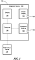
- Fig. 1 schematically shows an integrated device 100 in accordance with an illustrative embodiment of the invention.
- the device 100 delivers both optical and direct current stimulation to a subj ect in order to achieve synergistic visual field restoration.
- the integrated device includes a housing 110, which contains at least one current source (i.e., an electrical power supply connectable to one or more circuits) 120 and at least one of a display 130, and/or a computer 140 in data communication with the display 130.
- Patient response device 170 e.g., a mouse
- Each current source 120 may have a connector terminal for connecting an electrode assembly.
- the integrated device 100 of Fig. 1 also includes an optional feedback module 160 that makes measurements related to neuronal activity and allows adjustment of stimulative parameters of the device based on the measurements; an example of a feedback module is the EEG module described below.
- Electrodes may be implanted into the brain, but for greater convenience and safety, and to lower the cost of the procedure, the electrodes may be attached to the skin.
- the skin-attached electrodes may be coated with a conducting gel to ensure acceptable conduction.
- one or more stimulation electrodes and one ore more reference electrodes are placed on the skin of the subject's head.
- the electrodes may be positioned to cause current flow to intersect with the patient's CNS, including areas related to vision. For example, a single stimulation and a single reference electrode may be used or an array of electrodes may be used.
- a pad or sponge electrode (e.g., impregnated with saline) may be also be used.
- U.S. Patent 6,263,226 to Axelgaard issued July 17, 2001 describes a sponge electrode.
- a pad or sponge electrode may have the advantage of applying current diffusely across a large area of skin. However, a large area may also be covered using a spaced-apart array of electrodes.
- the electrode array may be integrated into a soft, elastic cap that applies an elastic force to hold an array of spaced-apart electrodes against the subject's head.
- an anodal electrode is applied in the immediate region of the occipital lobe, and a reference electrode (cathode) applied elsewhere, in a manner such that the direct current stimulation will flow at least in part through the visual cortex.
- a reference electrode cathode
- US Patents 4,092,985 ; 3,977,392 ; 3,376,870 ; 2,943,627 ; 6,208,902 ; 7317,947 and RE31,454 discloses electrodes that may be used with embodiments of the invention. Additionally a tripolar, concentric-ring, or double-concentric ring electrode arrangement may be used.
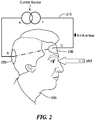
- Fig. 2 schematically shows an embodiment of the invention in which a patient 200 is connected to a galvanic stimulation circuit 210 via an anodic electrode 220 and a cathodic electrode 230.
- the electrodes (220,230) are positioned to direct electron flow through the visual cortex of the patient 200.
- a current source is used to deliver a DC current through the visual cortex. The current is limited to 5 mA or less.
- Optical stimuli e.g., VRT
- VRT Optical stimuli
- Electrodes may be placed in close proximity to at least a portion of the visual system (e.g. the visual cortex) to establish a current path through the visual system portion. Placement of the electrodes may be difficult for an individual user or lay caregiver to perform. For example, hair may interfere with establishing adequate electrical contact, electrodes may drip saline and result in uncontrolled stray currents on the skin, and the electrodes may be difficult to properly and consistently position on the scalp. An occipital lobe electrode may be especially difficult to place due to the need for location at the back of the head.
- electrodes including the reference electrode may be implanted subcutaneously, e.g., beneath the scalp of the patient.
- a surgeon may implant two electrodes under the scalp.
- the electrodes may be powered either via a transdermal subminiature connector or magnetically, via a power-coupling wand which the patient or caregiver positions above the electrodes.
- Methods for implanting electrodes and coupling them to external power sources are known in the art; for example, US Patents Nos. 7,010,351 , 75,540,736 , and 6,208,902 discloses a variety of such methods.
- at least one stimulation electrode is implanted subcutaneously and above the skull along with a first induction coil and associated circuitry.
- An external device that includes a second induction coil connected to a power source is held in proximity to the first induction coil to transfer energy through the skin and induce a current flow.
- the anode may be located just above the occipital lobe, and the reference electrode (cathode) in a location which would favor a current path through the visual cortex. As a result, a reliable and consistent DC current path is established.
- a cortical stimulation electrode is implanted under the scalp, and in close proximity to the occipital lobe.
- the cortical stimulation electrode is accessible via a transdermal subminiature connector.
- One or more reference electrodes are positioned externally (on the skin), and may be applied to the forehead during each session. The reference electrodes are positioned to establish a current path through the visual cortex.
- an electrode may be placed around the subject's eye to stimulate and thereby treat the retina of a subject with a retinal deficit.
- the electrode may be an annular electrode applied to the orbit of the eye (i.e., an orbital electrode), that allows the patient to see through the electrode.
- Use of such an electrode will allow the subject to receive optical stimuli via a corneal pathway while wearing the electrode.
- a reference electrode may be placed on the skin on the occiput (i.e., an occipital electrode) so that stimulation current may flow between the electrodes and through the subject's retina and ocular structures, along the optic nerve, though the occipital lobe, and to the reference electrode.
- the current used for the purpose of therapy may be imperceptible to the patient. Consequently, the patient cannot determine if the current is actually flowing.
- the computer may continuously monitor the output of each current source, and may notify the patient that the electrodes have been properly placed and that current is flowing. During therapy, the device may notify the subject, if, for any reason the current of one or more of the current sources is interrupted. In response, the subject or caregiver may then suspend therapy until the current flow is resumed. For example, if the computer detects an elevated contact resistance with the skin indicative of a dislodged electrode, a warning message or sound may be presented via the display or a computer associated loudspeaker.
- both galvanic and visual therapies can be suspended.
- the subject may thereby be allowed to disconnect from the device and return at a later time to resume a sequence of therapy.
- the current source may be a constant current source.
- the constant current source may comprise, for example a battery, a rechargeable battery, or an isolated power supply together with necessary circuitry to produce a constant current that is independent of the load applied to the current source.
- the current produced by the constant current source is independent from a connected load.
- a constant current source may produce a current with an intensity of 500 ⁇ A ⁇ 10% (standard deviation) in the presence of either a 5,000 Ohm or a 10,000 Ohm resistor.
- the constant current source may produce a current of 1 mA with ⁇ 10 %(standard deviation) in intensity when the load is varied from 10,000 Ohms to 100,000 Ohms.
- the constant current source intensity may be programmable and may be controlled by the computer 140 and associated software.
- a representative embodiment has available settings from between 1 and 5 mA, adjustable in 1 ⁇ A steps, and may effectively handle loads (i.e., inter-electrode resistance) of between 5000 Ohm. to 100,000 Ohm.
- the computer 140 may include a safety feature that ensures that the voltage resulting from the direct current flowing through the inter-electrode resistance never exceeds a safe and comfortable level of 20 VDC or less.
- each current source may have one or more terminal connectors (e.g., that donate or accept a pin or banana-plug) that are accessible through the housing.
- the current source may deliver a current via the electrode assembly that is in the range of 5 ⁇ A to 10 mA, and more preferably between 10 ⁇ A and 5 mA.
- the computer may control one or more electrical parameters. For example, the current may be turned on, turned off, the intensity/amplitude adjusted or voltage limited, and the electrical polarity switched in response to computer command.
- the computer based on a therapy profile specific to the subject, may set the intensity of current or other electrical output parameter.
- the computer may also log the current level at one or more times during therapy for later review; for example, a log entry may be created every second.
- the logged information may be associated with files holding other session information such as the user biographic profile, therapy history, subject performance information, and visual field maps.
- the computer may include a timer for synchronizing the presentation of optical and galvanic stimuli.
- the synchronization may include measuring a predetermined time relationship between application of the optical and galvanic stimuli.
- Direct current application may be administered before, during, or after optical stimulation (including single stimulation events and sequences or courses of optical stimulation therapy).
- the timing of the direct current and optical stimulation may be offset by a predetermined amount. For example, direct current stimulation may precede the presentation of an optical stimulation by a period of between 3 seconds and 30 minutes.
- the current may also be applied in a continuous manner throughout a session of optical stimulation therapy for time periods lasting from a few minutes to several hours.
- direct current stimulation may be applied after the optical stimulation, thereby synergistically enhancing (i.e., consolidating) the therapeutic effects of the previous visual stimulation.
- the computer may also record, via an input device, the subject's perception or lack of perception of the electrical stimulation.
- the location of the visual stimuli on the display, and the galvanic stimulation may be adjusted to reflect changes in the patient response to the stimuli in specific zones of the patient visual field. Adjustments of the galvanic stimulation during therapy may include changes amperage (intensity), current polarity, duration of current flow, and electrode locations.
- multiple current sources may also be integrated into the device.
- Using multiple current sources facilitates stimulation of various parts of the CNS with different electronic regimes (e.g. current, polarity or timings). For example, in a therapeutic regime that includes stimulation of independent CNS regions, a first pair of electrodes is applied to occipital lobe and delivers a current having a first intensity, while a second pair, connected to a second current source stimulates the optic nerve with a second intensity.
- a first pair of electrodes is applied to occipital lobe and delivers a current having a first intensity
- a second pair connected to a second current source stimulates the optic nerve with a second intensity.
- the respective current sources may be controlled independently.
- the computer may independently trigger switching the current on and off, alter current levels, etc.
- One or more current source may be electrically isolated (i.e., floating) with respect to other current sources.
- multiple independent reference electrodes may be used effectively.
- Multiple current sources, electrically floating with respect to each other, are useful in better managing stray currents between electrodes applied to separate regions of the CNS
- each current source may also be electrically isolated with respect to the electrical ground on the device.
- Each current source may have a pair of terminals located on the housing of the device for interfacing with reference and stimulation electrode assemblies.
- the computer may also log data regarding operation of the multiple current sources.
- the galvanic stimulation may comprise application of a relatively small current, e.g., a direct current of between 10 ⁇ A and 5 mA.
- the galvanic stimulation may be applied for a long period, e.g., up to 3 hours.
- the computer 140 may be programmed with specific current limits and Coulomb limits for subject exposure over established period of time (e.g., an hour or day). Maximum exposure thresholds may be associated with a given subject via use of a subject identifier, e.g., a username, smart-card, etc.
- Coulomb exposure can be tracked for each subject. Once a maximum Coulomb exposure threshold is reached, the therapy could be terminated or optical stimulation (e.g., VRT) could continue without the galvanic stimulation. Resumption of galvanic stimulation may then be permitted after an established recovery period measured by the computer.
- optical stimulation e.g., VRT
- An embodiment of the device that further enhances the safety of the application of galvanic stimulation to the visual system of a patient incorporates includes a feedback module 160 that continuously monitor an EEG (electroencephalogram) of the patient during the galvanic stimulation.
- EEG electroencephalogram
- This EEG may be recorded using the same electrodes used for the galvanic stimulation, or a separate system of electrodes. If a separated set of electrodes are used, the integrated device may have connection ports to accommodate leads from these electrodes.
- the EEG may be processed using a real-time algorithm which repeatedly analyzes brain activity and adjusts the amount and characteristics of the direct current stimulation.
- a common housing may house the direct current source, the EEG circuitry, the computer and all necessary software required to monitor the EEG in real-time and correspondingly adapt the direct current stimulation.
- Such an embodiment may include the display, or the display can be a separate Head Mounted Device (HMD), which may incorporate within its structure, direct current stimulation electrodes and/or EEG electrodes.
- the direct current may be isolated from the EEG circuitry using capacitors.
- the device may include circuitry to filter and process the EEG signal to remove the galvanic stimulation signal and other noise; using, for example, a digital signal processor (DSP).
- DSP digital signal processor
- This circuitry may include at least one isolation transformer.
- the EEG feedback module may incorporate principles or hardware of known EEG monitoring systems; for example, BIS Technology, which is commercialized by Aspect Medical Systems, Inc or Norwood, MA ( www.aspectmedical.com) .
- the display may be any suitable computer-driven display; for example, a CRT, LCD, plasma, SED, or OLED.
- the display may be a desktop-type display, adjustably mounted, or may be a head mounted display (e.g., goggles or a helmet). If a head mounted display is used, the current source and computer may be separately housed to decrease the weight and bulk of the head mounted device portion.
- the head mounted display may be in wired or wireless communication with the computer.
- stimulation and EEG electrodes may be integrated with the head mounted display.
- patients may be used to deliver VRT according to a variety of optical stimulation, testing and feedback regimes.
- the VRT therapy typically includes creating a visual field map, targeting particular zones of the visual field with optical stimuli, measuring the resulting changes in the visual field, and redefining the zones based on the revised measurement.
- Optical stimulation regimes may be supplemented with electrical stimulation as described above. These regimes include those described in the referenced listed in table below. Table 1.
- U.S. Patent No. 6,464,356 U.S. Published application No. 2005-0213033
- a variety of schemes may be used to synchronize the galvanic therapy with the VRT.
- galvanic stimulation may be applied before, during or after a VRT session, and may be applied continuously or in a series of pulses.
- Combination of the aforementioned electrical and optical stimulation may provide synergistic therapeutic effects. In other words, greater degrees and rates of improvement may be possible using the combined stimulation approach than may be obtained by either individually.
- the synergistic effect may involve increased cortical excitability due to galvanic stimulation.
- embodiments described herein may be effective in the treatment of vision loss including vision loss resulting from neurological damage of visual cortex or optic nerve. Such neurological damage may result from stroke, traumatic brain injury, and age related macular degeneration, among others.
- the disclosed methods for visual field stimulation may be implemented as a computer program product for use with a computer system.
- Such implementations may include a series of computer instructions fixed either on a tangible medium, such as a computer readable medium (e.g. , a diskette, CD-ROM, ROM, or fixed disk) or transmittable to a computer system, via a modem or other interface device, such as a communications adapter connected to a network over a medium.
- the medium may be either a tangible medium (e.g ., optical or analog communications lines) or a medium implemented with wireless techniques (e.g. , microwave, infrared or other transmission techniques).
- the series of computer instructions embodies all or part of the functionality previously described herein with respect to the system. Those skilled in the art should appreciate that such computer instructions can be written in a number of programming languages for use with many computer architectures or operating systems.
- Such instructions may be stored in any memory device, such as semiconductor, magnetic, optical or other memory devices, and may be transmitted using any communications technology, such as optical, infrared, microwave, or other transmission technologies.
- a computer program product may be distributed as a removable medium with accompanying printed or electronic documentation (e.g. , shrink wrapped software), preloaded with a computer system ( e.g., on system ROM or fixed disk), or distributed from a server or electronic bulletin board over the network (e.g ., the Internet or World Wide Web).
- some embodiments of the invention may be implemented as a combination of both software (e.g. , a computer program product) and hardware. Still other embodiments of the invention are implemented as entirely hardware, or entirely software (e.g., a computer program product).
Landscapes
- Health & Medical Sciences (AREA)
- Ophthalmology & Optometry (AREA)
- Engineering & Computer Science (AREA)
- Biomedical Technology (AREA)
- Nuclear Medicine, Radiotherapy & Molecular Imaging (AREA)
- Radiology & Medical Imaging (AREA)
- Life Sciences & Earth Sciences (AREA)
- Animal Behavior & Ethology (AREA)
- General Health & Medical Sciences (AREA)
- Public Health (AREA)
- Veterinary Medicine (AREA)
- Electrotherapy Devices (AREA)
Claims (13)
- Dispositif intégré (100) pour l'amélioration du système visuel d'un sujet humain (200) doté d'un oeil, d'une tête et d'un crâne, ce dispositif comprenant :- un ordinateur (140) en communication de données avec un afficheur (130), l'ordinateur (140) et l'afficheur (130) étant aptes à présenter des stimuli optiques à une région ciblée d'un oeil, l'ordinateur (140) comprenant un temporisateur pour mesurer une relation temporelle ;- une source de courant (120) comportant au moins un connecteur pour la connexion d'un ensemble d'électrodes (220, 230),- la source de courant (120) fournissant une stimulation électrique au cerveau du sujet (200) et l'afficheur (130) fournissant une stimulation électrique au système visuel du sujet (200) en relation temporelle,- la relation temporelle incluant la fourniture de la stimulation électrique avant, concurremment ou subséquemment à la stimulation optique,caractérisé par un boîtier (110) apte à contenir la source de courant en combinaison avec au moins un élément parmi l'afficheur et l'ordinateur,
l'ordinateur (140) étant apte à commander la source de courant (120) de manière à ne pas dépasser des limites de courant spécifiques et des limites de Coulomb spécifiques pour l'exposition du sujet humain (200) pendant une durée établie. - Dispositif selon la revendication 1, dans lequel l'ensemble d'électrodes (220, 230) comprend un élément parmi une électrode, un réseau d'électrodes, une électrode orbitale et une électrode à éponge.
- Dispositif selon la revendication 1, dans lequel
l'ensemble d'électrodes (220, 230) comprend au moins une électrode implantée. - Dispositif selon la revendication 3, dans lequel
électrode implantée est implantée sous la peau à proximité immédiate du cortex visuel. - Dispositif selon la revendication 4, dans lequel l'électrode implantée comprend une première bobine d'induction pour le couplage inductif d'énergie en provenance d'un dispositif externe vers l'électrode de stimulation.
- Dispositif selon l'une quelconque des revendications 3 ou 4, comprenant en outre un actionneur externe pour alimenter et actionner de manière inductive l'électrode implantée sans contact physique direct entre l'actionneur et l'électrode, l'actionneur comprenant particulier une seconde bobine d'induction.
- Dispositif selon la revendication 1, dans lequel l'ensemble d'électrodes (220, 230) est apte à effectuer une stimulation transcrânienne ciblant le lobe occipital avec du courant anodique.
- Dispositif selon la revendication 7, dans lequel le boîtier (110) est apte à être monté sur la tête.
- Dispositif selon la revendication 1, dans lequel la connexion d'un terminus de l'ensemble d'électrodes au dispositif et d'un autre terminus de l'ensemble d'électrodes au sujet établit un flux de courant direct du dispositif au sujet.
- Dispositif selon la revendication 1, dans lequel la source de courant (120) et l'ordinateur (140) partagent un boîtier commun et/ou dans lequel la source de courant (120) et l'afficheur (130) partagent un boîtier commun.
- Dispositif selon la revendication 1, comprenant en outre un module de retour (160), le module de retour comprenant en particulier un module EEG.
- Dispositif selon la revendication 11, comprenant en outre- au moins un condensateur pour isoler un signal EEG d'un signal de stimulation galvanique, Ou- au moins un transformateur d'isolation pour isoler le module EEG d'un signal de stimulation galvanique.
- Dispositif selon la revendication 1, comprenant en outre une seconde source de courant, les première et seconde sources de courant étant en particulier isolées électriquement.
Applications Claiming Priority (2)
| Application Number | Priority Date | Filing Date | Title |
|---|---|---|---|
| US88607307P | 2007-01-22 | 2007-01-22 | |
| PCT/US2008/051673 WO2008091876A1 (fr) | 2007-01-22 | 2008-01-22 | Dispositif pour traiter la vision humaine en utilisant une stimulation optique et électrique combinée |
Publications (2)
| Publication Number | Publication Date |
|---|---|
| EP2114517A1 EP2114517A1 (fr) | 2009-11-11 |
| EP2114517B1 true EP2114517B1 (fr) | 2017-07-12 |
Family
ID=39367505
Family Applications (1)
| Application Number | Title | Priority Date | Filing Date |
|---|---|---|---|
| EP08728049.1A Not-in-force EP2114517B1 (fr) | 2007-01-22 | 2008-01-22 | Dispositif pour traiter la vision humaine en utilisant une stimulation optique et électrique combinée |
Country Status (3)
| Country | Link |
|---|---|
| US (2) | US20080177352A1 (fr) |
| EP (1) | EP2114517B1 (fr) |
| WO (1) | WO2008091876A1 (fr) |
Families Citing this family (19)
| Publication number | Priority date | Publication date | Assignee | Title |
|---|---|---|---|---|
| US8396570B2 (en) * | 2009-01-02 | 2013-03-12 | Cochlear Limited | Combined optical and electrical neural stimulation |
| US20150018667A1 (en) * | 2012-01-30 | 2015-01-15 | The United States Of America, As Represented By The Secretary, Dept. Of Health And Human Services | Promoting transcranial direct current stimulation or transcranial magnetic stimulation using temperature-induced synaptic modulation |
| US8909344B2 (en) * | 2013-03-07 | 2014-12-09 | Jeffrey Edward Arle | Head worn brain stimulation device and method |
| US9630005B2 (en) | 2013-08-27 | 2017-04-25 | Halo Neuro, Inc. | Method and system for providing electrical stimulation to a user |
| US9486618B2 (en) | 2013-08-27 | 2016-11-08 | Halo Neuro, Inc. | Electrode system for electrical stimulation |
| US9889290B2 (en) | 2013-08-27 | 2018-02-13 | Halo Neuro, Inc. | Electrode system for electrical stimulation |
| US9782585B2 (en) | 2013-08-27 | 2017-10-10 | Halo Neuro, Inc. | Method and system for providing electrical stimulation to a user |
| ES2809567T3 (es) | 2013-11-04 | 2021-03-04 | Phoenix Neurostim Therapeutics Llc | Dispositivo para el tratamiento de las condiciones del sistema nervioso central utilizando un estímulo sensorial |
| KR20160145131A (ko) * | 2014-04-17 | 2016-12-19 | 더 리전트 오브 더 유니버시티 오브 캘리포니아 | 시야 결함들의 평가를 위한 휴대용 뇌 활동 감지 플랫폼 |
| US9931266B2 (en) | 2015-01-30 | 2018-04-03 | Magno Processing Systems, Inc. | Visual rehabilitation systems and methods |
| US10946165B2 (en) | 2015-05-04 | 2021-03-16 | Phoenix Neurostim Therapeutics, Llc | Modulation of brainwave activity using non-invasive stimulation of sensory pathways |
| EP3368146B1 (fr) | 2015-10-26 | 2021-04-07 | Halo Neuro, Inc. | Système de positionnement d'électrode |
| ITUB20154761A1 (it) | 2015-10-29 | 2017-04-29 | Resono Ophthalmic S R L | Sistema di elettrodo e relativo dispositivo per il trattamento di patologie dell?occhio, in particolare dell?occhio secco |
| WO2017139243A1 (fr) | 2016-02-08 | 2017-08-17 | Halo Neuro, Inc. | Procédé et système permettant d'améliorer la fourniture d'une stimulation électrique |
| US10485443B2 (en) | 2016-06-20 | 2019-11-26 | Halo Neuro, Inc. | Electrical interface system |
| WO2018165481A1 (fr) | 2017-03-08 | 2018-09-13 | Halo Neuro, Inc. | Système pour stimulation électrique |
| US10507324B2 (en) | 2017-11-17 | 2019-12-17 | Halo Neuro, Inc. | System and method for individualizing modulation |
| WO2019241318A1 (fr) | 2018-06-13 | 2019-12-19 | Cornell University | Marqueurs bioluminescents d'activité neuronale |
| EP3603737B1 (fr) | 2018-07-31 | 2020-08-26 | Flow Neuroscience AB | Positionnement d'électrodes pour une stimulation cérébrale transcrânienne |
Family Cites Families (115)
| Publication number | Priority date | Publication date | Assignee | Title |
|---|---|---|---|---|
| US239754A (en) * | 1881-04-05 | Platform rocking-chair | ||
| US145630A (en) * | 1873-12-16 | Improvement in rails for sliding doors | ||
| US12042A (en) * | 1854-12-05 | Hydraulic ram | ||
| US36971A (en) * | 1862-11-18 | Improvement in the dobersiner hydrogen lighter | ||
| US147463A (en) * | 1874-02-10 | Improvement in rufflers for sewing-machines | ||
| US113859A (en) * | 1871-04-18 | Improvement in preparing flour for use in confectionery | ||
| US209578A (en) * | 1878-11-05 | Improvement in oil-cans | ||
| US180808A (en) * | 1876-08-08 | Improvement in loom-harness | ||
| US2053072A (en) * | 1931-05-04 | 1936-09-01 | Farmer Bros Co | Circulation control for percolators |
| US2213484A (en) * | 1939-07-22 | 1940-09-03 | Henry H Briggs | Apparatus for visual training |
| US3002190A (en) * | 1955-04-15 | 1961-09-26 | Zenith Plastics Company | Multiple sandwich broad band radome |
| BE553931A (fr) * | 1956-01-04 | |||
| US2943627A (en) * | 1957-04-05 | 1960-07-05 | William L Howell | Electrode |
| US3007944A (en) * | 1958-01-20 | 1961-11-07 | Exxon Research Engineering Co | Process for the oxidation of trialkyl ethylene hydrocarbons |
| US3041630A (en) * | 1959-07-27 | 1962-07-03 | Williams Richard Wendell | Water closet flushing apparatus |
| US3065964A (en) * | 1959-08-10 | 1962-11-27 | Paul J Barnes | Game net mounting post |
| US3020195A (en) * | 1960-02-29 | 1962-02-06 | Glatfelter Co P H | Production of potassium compounds |
| US3098529A (en) * | 1960-03-07 | 1963-07-23 | Wade Robert Edgar | Plow clamping means |
| US3092570A (en) * | 1960-08-01 | 1963-06-04 | Socony Mobil Oil Co Inc | Removal of aromatic hydrocarbons from jet fuel mixtures |
| US3002070A (en) * | 1960-09-01 | 1961-09-26 | Mc Graw Edison Co | Fuse cutout |
| US3376870A (en) * | 1965-03-08 | 1968-04-09 | Yamamoto Yujiro | Cranial electrode construction for sleep inducing machine |
| US3883234A (en) * | 1970-07-13 | 1975-05-13 | John R Lynn | Computer controlled apparatus for automatic visual field examination |
| US4092985A (en) * | 1974-11-25 | 1978-06-06 | John George Kaufman | Body electrode for electro-medical use |
| US3977392A (en) * | 1975-04-21 | 1976-08-31 | Eastprint, Inc. | Medical electrode |
| USRE31454E (en) * | 1975-11-25 | 1983-12-06 | Lectec Corporation | Monitoring and stimulation electrode |
| US4260227A (en) * | 1977-10-04 | 1981-04-07 | Coherent, Inc. | Automated kinetic perimetry apparatus and method |
| US4408846A (en) * | 1981-02-02 | 1983-10-11 | Andrew M. Clay | Method and apparatus for increasing visual acuity |
| US4429961A (en) * | 1981-08-14 | 1984-02-07 | Sheingorn Larry A | Visual field testing device |
| US4660945A (en) * | 1983-01-25 | 1987-04-28 | Trachtman Joseph N | Methods and apparatus for accommodation training |
| US4533221A (en) * | 1983-01-25 | 1985-08-06 | Trachtman Joseph N | Methods and apparatus for accommodation training |
| US4679920A (en) * | 1984-02-24 | 1987-07-14 | Tokyo Kogaku Kikai Kabushiki Kaisha | Automatic perimeter |
| US5325136A (en) * | 1988-12-12 | 1994-06-28 | Prio Corporation | Computer display screen simulation for optometric examination |
| US4998820A (en) * | 1988-12-12 | 1991-03-12 | Applied Vision Concepts, Inc. | Instrument and method for use in optometric examinations |
| US5088810A (en) * | 1989-01-23 | 1992-02-18 | Galanter Stephen M | Vision training method and apparatus |
| RU1799577C (ru) * | 1989-08-17 | 1993-03-07 | Межотраслевой научно-технический комплекс "Микрохирургия глаза" | Способ улучшени зрительных функций при заболевани х зрительного нерва и сетчатки и устройство дл его осуществлени |
| US4995717A (en) * | 1989-08-22 | 1991-02-26 | The University Court Of The University Of Glasgow | Device for moving eye campimetry |
| US5050982A (en) * | 1989-10-06 | 1991-09-24 | Meissner Juergen P | Method and apparatus for improving visual acuity |
| US4971434A (en) * | 1989-11-28 | 1990-11-20 | Visual Resources, Inc. | Method for diagnosing deficiencies in and expanding a person's useful field of view |
| US5139323A (en) * | 1990-01-10 | 1992-08-18 | Schillo Paula L | Hemianopsia rehabilitation training system |
| US5206671A (en) * | 1990-06-29 | 1993-04-27 | Eydelman Malvina B | Testing and treating of visual dysfunctions |
| IT1252873B (it) * | 1991-11-26 | 1995-07-03 | Apparecchio e metodo per allenamento visivo in funzione della riflessione retinica | |
| US5241332A (en) * | 1991-11-29 | 1993-08-31 | Farrell Joyce M | Treatment modality in occupational therapy |
| US5305027A (en) * | 1992-01-28 | 1994-04-19 | Patterson Kip E | Method and apparatus for enhanced visual training |
| US5539482A (en) * | 1992-02-28 | 1996-07-23 | The Australian National University | Glaucoma testing using non-linear systems identification techniques |
| US6062687A (en) * | 1992-11-09 | 2000-05-16 | Lofgren-Nisser; Gunilla | Partially occluded contact lens for treating visual and/or brain disorder |
| KR940018979U (ko) * | 1993-01-28 | 1994-08-16 | 성기호 | 시력향상 및 색각교정기 |
| US6359601B1 (en) * | 1993-09-14 | 2002-03-19 | Francis J. Maguire, Jr. | Method and apparatus for eye tracking |
| AUPM537994A0 (en) * | 1994-04-29 | 1994-05-26 | Australian National University, The | Early detection of glaucoma |
| EP0689822B1 (fr) * | 1994-07-01 | 1997-10-01 | Fritz Prof. Dr.Dr.Dr. Schmielau | Dispositif d'exercise pour traiter des patients souffrant de troubles de la perception |
| US5522864A (en) * | 1994-10-25 | 1996-06-04 | Wallace; Larry B. | Apparatus and method for ocular treatment |
| US5550602A (en) * | 1994-11-09 | 1996-08-27 | Johannes Braeuning | Apparatus and method for examining visual functions |
| US5539481A (en) * | 1994-12-22 | 1996-07-23 | Vax; Guennadi | Acuity therapy apparatus and method thereof |
| US5991085A (en) * | 1995-04-21 | 1999-11-23 | I-O Display Systems Llc | Head-mounted personal visual display apparatus with image generator and holder |
| US5565949A (en) * | 1995-07-10 | 1996-10-15 | Kasha, Jr.; John R. | Visual field perimetry on a small computer screen |
| US5946075A (en) * | 1996-05-21 | 1999-08-31 | Horn; Gerald | Vision screening system |
| US6386706B1 (en) * | 1996-07-31 | 2002-05-14 | Virtual-Eye.Com | Visual function testing with virtual retinal display |
| US6592222B2 (en) * | 1996-07-31 | 2003-07-15 | Massengill Family Trust | Flicker and frequency doubling in virtual reality |
| US20030156383A1 (en) * | 1996-08-29 | 2003-08-21 | Jenkins Michael D. | Core computer system |
| US5883692A (en) * | 1997-10-01 | 1999-03-16 | Retsan, Inc. | Visual field measurement apparatus |
| US6016449A (en) * | 1997-10-27 | 2000-01-18 | Neuropace, Inc. | System for treatment of neurological disorders |
| US6038464A (en) * | 1998-02-09 | 2000-03-14 | Axelgaard Manufacturing Co., Ltd. | Medical electrode |
| AU741194B2 (en) * | 1998-04-10 | 2001-11-22 | Visual Awareness Research Group, Inc. | Method and apparatus for training visual attention capabilities of a subject |
| HK1040048B (zh) * | 1998-08-27 | 2011-11-25 | Novavision, Inc. | 用於锻练人类视力的方法和装置 |
| US6208902B1 (en) * | 1998-10-26 | 2001-03-27 | Birinder Bob Boveja | Apparatus and method for adjunct (add-on) therapy for pain syndromes utilizing an implantable lead and an external stimulator |
| US6321338B1 (en) * | 1998-11-09 | 2001-11-20 | Sri International | Network surveillance |
| US6299632B1 (en) * | 1998-11-30 | 2001-10-09 | Peter Jaillet | Method for changing critical brain activity using light and sound |
| JP3640830B2 (ja) * | 1999-03-30 | 2005-04-20 | 株式会社ニデック | 眼科装置 |
| WO2000072083A1 (fr) * | 1999-05-06 | 2000-11-30 | Stregova Erzsebet | Dispositif destine au conditionnement de l'oeil et a l'amelioration de la vue |
| US6540355B1 (en) * | 1999-12-20 | 2003-04-01 | Paul M. Couture | Computerized eye testing and exercises |
| US6431708B2 (en) * | 1999-12-21 | 2002-08-13 | Paul A. Krebs | Vision therapy system and method |
| US7004912B2 (en) * | 1999-12-27 | 2006-02-28 | Neurovision, Inc. | Systems and methods for improving visual perception |
| US6519703B1 (en) * | 2000-04-14 | 2003-02-11 | James B. Joyce | Methods and apparatus for heuristic firewall |
| RU2187237C2 (ru) * | 2000-04-27 | 2002-08-20 | Туровецкий Владимир Наумович | Способ улучшения зрения и/или профилактики ухудшения зрения пользователей устройств для видеоизображения |
| US7146209B2 (en) * | 2000-05-08 | 2006-12-05 | Brainsgate, Ltd. | Stimulation for treating eye pathologies |
| US7010351B2 (en) * | 2000-07-13 | 2006-03-07 | Northstar Neuroscience, Inc. | Methods and apparatus for effectuating a lasting change in a neural-function of a patient |
| US6406437B1 (en) * | 2000-10-11 | 2002-06-18 | Yeda Research And Development Co. Ltd. | Method and apparatus for efficient high-resolution visual field mapping |
| JP2004517658A (ja) * | 2000-11-22 | 2004-06-17 | カール ツァイス イェナ ゲーエムベーハー | 視覚系を光学的に刺激するための方法および装置 |
| RU2174382C1 (ru) * | 2001-01-05 | 2001-10-10 | Еремеев Александр Павлович | Способ и устройство спектральной оптико-рефлекторной терапии для улучшения зрения (варианты) |
| US7444404B2 (en) * | 2001-02-05 | 2008-10-28 | Arbor Networks, Inc. | Network traffic regulation including consistency based detection and filtering of packets with spoof source addresses |
| US6416190B1 (en) * | 2001-04-27 | 2002-07-09 | University Of Chicago | Apparatus for using optical tweezers to manipulate materials |
| WO2003033070A1 (fr) * | 2001-10-16 | 2003-04-24 | Case Western Reserve University | Prothese neurale |
| US7853330B2 (en) * | 2001-12-04 | 2010-12-14 | Boston Scientific Neuromodulation Corporation | Apparatus and method for determining the relative position and orientation of neurostimulation leads |
| US7682021B2 (en) * | 2002-02-08 | 2010-03-23 | Novavision, Inc. | System and methods for the treatment of retinal diseases |
| CA2475042C (fr) * | 2002-02-08 | 2011-05-10 | Novavision, Inc. | Procede et dispositif perfectionnes d'entrainement de la vision humaine |
| US20070216865A1 (en) * | 2002-02-08 | 2007-09-20 | Novavision, Inc. | Process and Device for Apportioning Therapeutic Vision Stimuli |
| US7753524B2 (en) * | 2002-02-08 | 2010-07-13 | Novavision, Inc. | Process and device for treating blind regions of the visual field |
| US6742892B2 (en) * | 2002-04-16 | 2004-06-01 | Exercise Your Eyes, Llc | Device and method for exercising eyes |
| US20040075811A1 (en) * | 2002-04-16 | 2004-04-22 | Exercise Your Eyes, Inc. | Device and method for exercising eyes |
| JP3494375B1 (ja) * | 2002-04-30 | 2004-02-09 | 勝美 永吉 | トレーニングアイマスク |
| US6826042B2 (en) * | 2002-05-03 | 2004-11-30 | Hewlett-Packard Development Company, L.P. | Input device and methods and systems for same |
| US7033025B2 (en) * | 2002-05-17 | 2006-04-25 | Virtocc, Inc. | Interactive occlusion system |
| US20040012758A1 (en) * | 2002-07-19 | 2004-01-22 | Chao-Chyun Lin | Prism based dynamic vision training device and method thereof |
| JP4193444B2 (ja) * | 2002-08-16 | 2008-12-10 | コニカミノルタホールディングス株式会社 | 医用画像撮影装置、医用画像撮影方法及びプログラム |
| JP4300844B2 (ja) * | 2003-03-28 | 2009-07-22 | 株式会社ニコン | 眼機能訓練装置 |
| WO2005000153A2 (fr) * | 2003-04-24 | 2005-01-06 | Northstar Neuroscience, Inc. | Systemes et methodes permettant de favoriser et / ou de produire le developpement, la readaptation, la restauration et / ou la recuperation de la fonction visuelle par la stimulation neuronale |
| US7317947B2 (en) * | 2003-05-16 | 2008-01-08 | Medtronic, Inc. | Headset recharger for cranially implantable medical devices |
| US8001187B2 (en) * | 2003-07-01 | 2011-08-16 | Apple Inc. | Peer-to-peer active content sharing |
| US7033026B2 (en) * | 2003-07-04 | 2006-04-25 | Spector Robert T | Method of and apparatus for diagnosing and treating amblyopic conditions in the human visual system |
| US20050037177A1 (en) * | 2003-08-11 | 2005-02-17 | Streeton Amy B. | Non-migrating floor mat |
| US7343600B2 (en) * | 2003-08-18 | 2008-03-11 | Lenovo (Singapore) Pte. Ltd. | Providing an image of installed software utilizing uninstall code |
| US7107953B2 (en) * | 2003-09-18 | 2006-09-19 | Mitsubishi Jidosha Kogyo Kabushiki Kaisha | Valve gear of an internal combustion engine |
| US20050110326A1 (en) * | 2003-11-21 | 2005-05-26 | Leong Po S. | Dismantleable chair |
| JP4421448B2 (ja) * | 2003-12-04 | 2010-02-24 | シャープ株式会社 | 記録条件の設定方法及び設定装置、記録再生装置、記録条件設定プログラム及び記録媒体 |
| JP2005270451A (ja) * | 2004-03-25 | 2005-10-06 | Konica Minolta Photo Imaging Inc | 斜視訓練用虚像表示装置 |
| US7311536B2 (en) * | 2004-04-26 | 2007-12-25 | Valeo Schalter Und Sensoren Gmbh | Transmission device for transmitting electrical signals between a rotor and a stator |
| US7263403B2 (en) * | 2004-05-25 | 2007-08-28 | Second Sight Medical Products, Inc. | Retinal prosthesis |
| WO2006002070A2 (fr) * | 2004-06-15 | 2006-01-05 | Novavision, Inc. | Procede et dispositif permettant de guider la tete d'un utilisateur pendant un entrainement visuel |
| US7291298B2 (en) * | 2004-07-09 | 2007-11-06 | Husky Injection Molding Systems Ltd. | Apparatus and method for injection molding shooting pot wedge feature |
| EP1869521A1 (fr) * | 2005-03-30 | 2007-12-26 | Novavision, Inc. | Procede et dispositif pour fournir des stimuli visuels avec un visiocasque pendant un entrainement visuel |
| US7384146B2 (en) * | 2005-06-28 | 2008-06-10 | Carestream Health, Inc. | Health care kiosk having automated diagnostic eye examination and a fulfillment remedy based thereon |
| WO2007075460A2 (fr) * | 2005-12-16 | 2007-07-05 | Novavision, Inc. | Dispositif reglable pour test de vision et therapie |
| JP2009542368A (ja) * | 2006-06-30 | 2009-12-03 | ノバビジョン, インコーポレイテッド | 偏心視の診断および治療システム |
| US20080077437A1 (en) * | 2006-07-25 | 2008-03-27 | Novavision, Inc. | Process and Method for Providing Incentives to Increase Vision-Therapy Performance |
| US8029138B2 (en) * | 2006-07-25 | 2011-10-04 | Novavision, Inc. | Dynamic peripheral stimuli for visual field testing and therapy |
| JP4185141B2 (ja) * | 2007-02-05 | 2008-11-26 | ファナック株式会社 | 射出成形機の安全扉 |
-
2008
- 2008-01-22 US US12/017,919 patent/US20080177352A1/en not_active Abandoned
- 2008-01-22 WO PCT/US2008/051673 patent/WO2008091876A1/fr not_active Ceased
- 2008-01-22 EP EP08728049.1A patent/EP2114517B1/fr not_active Not-in-force
-
2010
- 2010-09-16 US US12/883,423 patent/US20110118806A1/en not_active Abandoned
Also Published As
| Publication number | Publication date |
|---|---|
| EP2114517A1 (fr) | 2009-11-11 |
| US20080177352A1 (en) | 2008-07-24 |
| WO2008091876A1 (fr) | 2008-07-31 |
| US20110118806A1 (en) | 2011-05-19 |
Similar Documents
| Publication | Publication Date | Title |
|---|---|---|
| EP2114517B1 (fr) | Dispositif pour traiter la vision humaine en utilisant une stimulation optique et électrique combinée | |
| US20240342472A1 (en) | Treatment of Headaches by Electrical Stimulation | |
| JP7541547B2 (ja) | 神経精神障害を治療するための装置、システム及び方法 | |
| US20140194948A1 (en) | Systems and methods for providing percutaneous electrical stimulation | |
| Dai et al. | Restoration of 3D vestibular sensation in rhesus monkeys using a multichannel vestibular prosthesis | |
| WO2018203132A1 (fr) | Système d'administration de stimulation électrique directe pour le traitement d'une maladie visuelle | |
| US20250073417A1 (en) | Systems, devices and methods for caloric and galvanic vestibular stimulation post anesthesia administration |
Legal Events
| Date | Code | Title | Description |
|---|---|---|---|
| PUAI | Public reference made under article 153(3) epc to a published international application that has entered the european phase |
Free format text: ORIGINAL CODE: 0009012 |
|
| 17P | Request for examination filed |
Effective date: 20090821 |
|
| AK | Designated contracting states |
Kind code of ref document: A1 Designated state(s): AT BE BG CH CY CZ DE DK EE ES FI FR GB GR HR HU IE IS IT LI LT LU LV MC MT NL NO PL PT RO SE SI SK TR |
|
| 17Q | First examination report despatched |
Effective date: 20100316 |
|
| DAX | Request for extension of the european patent (deleted) | ||
| 19U | Interruption of proceedings before grant |
Effective date: 20100428 |
|
| 19W | Proceedings resumed before grant after interruption of proceedings |
Effective date: 20120601 |
|
| RAP1 | Party data changed (applicant data changed or rights of an application transferred) |
Owner name: NOVAVISION INC. |
|
| REG | Reference to a national code |
Ref country code: DE Ref legal event code: R079 Ref document number: 602008051058 Country of ref document: DE Free format text: PREVIOUS MAIN CLASS: A61N0001180000 Ipc: A61N0001360000 |
|
| RIC1 | Information provided on ipc code assigned before grant |
Ipc: A61B 5/0482 20060101ALI20161121BHEP Ipc: A61N 1/36 20060101AFI20161121BHEP Ipc: A61B 5/0484 20060101ALI20161121BHEP |
|
| GRAP | Despatch of communication of intention to grant a patent |
Free format text: ORIGINAL CODE: EPIDOSNIGR1 |
|
| STAA | Information on the status of an ep patent application or granted ep patent |
Free format text: STATUS: GRANT OF PATENT IS INTENDED |
|
| INTG | Intention to grant announced |
Effective date: 20170202 |
|
| GRAS | Grant fee paid |
Free format text: ORIGINAL CODE: EPIDOSNIGR3 |
|
| GRAA | (expected) grant |
Free format text: ORIGINAL CODE: 0009210 |
|
| STAA | Information on the status of an ep patent application or granted ep patent |
Free format text: STATUS: THE PATENT HAS BEEN GRANTED |
|
| AK | Designated contracting states |
Kind code of ref document: B1 Designated state(s): AT BE BG CH CY CZ DE DK EE ES FI FR GB GR HR HU IE IS IT LI LT LU LV MC MT NL NO PL PT RO SE SI SK TR |
|
| REG | Reference to a national code |
Ref country code: GB Ref legal event code: FG4D |
|
| REG | Reference to a national code |
Ref country code: CH Ref legal event code: EP |
|
| REG | Reference to a national code |
Ref country code: AT Ref legal event code: REF Ref document number: 907777 Country of ref document: AT Kind code of ref document: T Effective date: 20170715 |
|
| REG | Reference to a national code |
Ref country code: IE Ref legal event code: FG4D |
|
| REG | Reference to a national code |
Ref country code: DE Ref legal event code: R096 Ref document number: 602008051058 Country of ref document: DE |
|
| REG | Reference to a national code |
Ref country code: NL Ref legal event code: MP Effective date: 20170712 |
|
| REG | Reference to a national code |
Ref country code: LT Ref legal event code: MG4D |
|
| REG | Reference to a national code |
Ref country code: AT Ref legal event code: MK05 Ref document number: 907777 Country of ref document: AT Kind code of ref document: T Effective date: 20170712 |
|
| REG | Reference to a national code |
Ref country code: FR Ref legal event code: PLFP Year of fee payment: 11 |
|
| PG25 | Lapsed in a contracting state [announced via postgrant information from national office to epo] |
Ref country code: SE Free format text: LAPSE BECAUSE OF FAILURE TO SUBMIT A TRANSLATION OF THE DESCRIPTION OR TO PAY THE FEE WITHIN THE PRESCRIBED TIME-LIMIT Effective date: 20170712 Ref country code: LT Free format text: LAPSE BECAUSE OF FAILURE TO SUBMIT A TRANSLATION OF THE DESCRIPTION OR TO PAY THE FEE WITHIN THE PRESCRIBED TIME-LIMIT Effective date: 20170712 Ref country code: FI Free format text: LAPSE BECAUSE OF FAILURE TO SUBMIT A TRANSLATION OF THE DESCRIPTION OR TO PAY THE FEE WITHIN THE PRESCRIBED TIME-LIMIT Effective date: 20170712 Ref country code: AT Free format text: LAPSE BECAUSE OF FAILURE TO SUBMIT A TRANSLATION OF THE DESCRIPTION OR TO PAY THE FEE WITHIN THE PRESCRIBED TIME-LIMIT Effective date: 20170712 Ref country code: HR Free format text: LAPSE BECAUSE OF FAILURE TO SUBMIT A TRANSLATION OF THE DESCRIPTION OR TO PAY THE FEE WITHIN THE PRESCRIBED TIME-LIMIT Effective date: 20170712 Ref country code: NO Free format text: LAPSE BECAUSE OF FAILURE TO SUBMIT A TRANSLATION OF THE DESCRIPTION OR TO PAY THE FEE WITHIN THE PRESCRIBED TIME-LIMIT Effective date: 20171012 Ref country code: NL Free format text: LAPSE BECAUSE OF FAILURE TO SUBMIT A TRANSLATION OF THE DESCRIPTION OR TO PAY THE FEE WITHIN THE PRESCRIBED TIME-LIMIT Effective date: 20170712 |
|
| PG25 | Lapsed in a contracting state [announced via postgrant information from national office to epo] |
Ref country code: PL Free format text: LAPSE BECAUSE OF FAILURE TO SUBMIT A TRANSLATION OF THE DESCRIPTION OR TO PAY THE FEE WITHIN THE PRESCRIBED TIME-LIMIT Effective date: 20170712 Ref country code: BG Free format text: LAPSE BECAUSE OF FAILURE TO SUBMIT A TRANSLATION OF THE DESCRIPTION OR TO PAY THE FEE WITHIN THE PRESCRIBED TIME-LIMIT Effective date: 20171012 Ref country code: LV Free format text: LAPSE BECAUSE OF FAILURE TO SUBMIT A TRANSLATION OF THE DESCRIPTION OR TO PAY THE FEE WITHIN THE PRESCRIBED TIME-LIMIT Effective date: 20170712 Ref country code: GR Free format text: LAPSE BECAUSE OF FAILURE TO SUBMIT A TRANSLATION OF THE DESCRIPTION OR TO PAY THE FEE WITHIN THE PRESCRIBED TIME-LIMIT Effective date: 20171013 Ref country code: ES Free format text: LAPSE BECAUSE OF FAILURE TO SUBMIT A TRANSLATION OF THE DESCRIPTION OR TO PAY THE FEE WITHIN THE PRESCRIBED TIME-LIMIT Effective date: 20170712 Ref country code: IS Free format text: LAPSE BECAUSE OF FAILURE TO SUBMIT A TRANSLATION OF THE DESCRIPTION OR TO PAY THE FEE WITHIN THE PRESCRIBED TIME-LIMIT Effective date: 20171112 |
|
| REG | Reference to a national code |
Ref country code: DE Ref legal event code: R097 Ref document number: 602008051058 Country of ref document: DE |
|
| PG25 | Lapsed in a contracting state [announced via postgrant information from national office to epo] |
Ref country code: CZ Free format text: LAPSE BECAUSE OF FAILURE TO SUBMIT A TRANSLATION OF THE DESCRIPTION OR TO PAY THE FEE WITHIN THE PRESCRIBED TIME-LIMIT Effective date: 20170712 Ref country code: RO Free format text: LAPSE BECAUSE OF FAILURE TO SUBMIT A TRANSLATION OF THE DESCRIPTION OR TO PAY THE FEE WITHIN THE PRESCRIBED TIME-LIMIT Effective date: 20170712 Ref country code: DK Free format text: LAPSE BECAUSE OF FAILURE TO SUBMIT A TRANSLATION OF THE DESCRIPTION OR TO PAY THE FEE WITHIN THE PRESCRIBED TIME-LIMIT Effective date: 20170712 |
|
| PLBE | No opposition filed within time limit |
Free format text: ORIGINAL CODE: 0009261 |
|
| STAA | Information on the status of an ep patent application or granted ep patent |
Free format text: STATUS: NO OPPOSITION FILED WITHIN TIME LIMIT |
|
| PG25 | Lapsed in a contracting state [announced via postgrant information from national office to epo] |
Ref country code: EE Free format text: LAPSE BECAUSE OF FAILURE TO SUBMIT A TRANSLATION OF THE DESCRIPTION OR TO PAY THE FEE WITHIN THE PRESCRIBED TIME-LIMIT Effective date: 20170712 Ref country code: SK Free format text: LAPSE BECAUSE OF FAILURE TO SUBMIT A TRANSLATION OF THE DESCRIPTION OR TO PAY THE FEE WITHIN THE PRESCRIBED TIME-LIMIT Effective date: 20170712 Ref country code: IT Free format text: LAPSE BECAUSE OF FAILURE TO SUBMIT A TRANSLATION OF THE DESCRIPTION OR TO PAY THE FEE WITHIN THE PRESCRIBED TIME-LIMIT Effective date: 20170712 |
|
| 26N | No opposition filed |
Effective date: 20180413 |
|
| PG25 | Lapsed in a contracting state [announced via postgrant information from national office to epo] |
Ref country code: SI Free format text: LAPSE BECAUSE OF FAILURE TO SUBMIT A TRANSLATION OF THE DESCRIPTION OR TO PAY THE FEE WITHIN THE PRESCRIBED TIME-LIMIT Effective date: 20170712 |
|
| REG | Reference to a national code |
Ref country code: CH Ref legal event code: PL |
|
| PG25 | Lapsed in a contracting state [announced via postgrant information from national office to epo] |
Ref country code: LU Free format text: LAPSE BECAUSE OF NON-PAYMENT OF DUE FEES Effective date: 20180122 |
|
| REG | Reference to a national code |
Ref country code: BE Ref legal event code: MM Effective date: 20180131 |
|
| PG25 | Lapsed in a contracting state [announced via postgrant information from national office to epo] |
Ref country code: CH Free format text: LAPSE BECAUSE OF NON-PAYMENT OF DUE FEES Effective date: 20180131 Ref country code: LI Free format text: LAPSE BECAUSE OF NON-PAYMENT OF DUE FEES Effective date: 20180131 Ref country code: BE Free format text: LAPSE BECAUSE OF NON-PAYMENT OF DUE FEES Effective date: 20180131 |
|
| PG25 | Lapsed in a contracting state [announced via postgrant information from national office to epo] |
Ref country code: MC Free format text: LAPSE BECAUSE OF FAILURE TO SUBMIT A TRANSLATION OF THE DESCRIPTION OR TO PAY THE FEE WITHIN THE PRESCRIBED TIME-LIMIT Effective date: 20170712 |
|
| PG25 | Lapsed in a contracting state [announced via postgrant information from national office to epo] |
Ref country code: MT Free format text: LAPSE BECAUSE OF NON-PAYMENT OF DUE FEES Effective date: 20180122 |
|
| PG25 | Lapsed in a contracting state [announced via postgrant information from national office to epo] |
Ref country code: TR Free format text: LAPSE BECAUSE OF FAILURE TO SUBMIT A TRANSLATION OF THE DESCRIPTION OR TO PAY THE FEE WITHIN THE PRESCRIBED TIME-LIMIT Effective date: 20170712 |
|
| PG25 | Lapsed in a contracting state [announced via postgrant information from national office to epo] |
Ref country code: HU Free format text: LAPSE BECAUSE OF FAILURE TO SUBMIT A TRANSLATION OF THE DESCRIPTION OR TO PAY THE FEE WITHIN THE PRESCRIBED TIME-LIMIT; INVALID AB INITIO Effective date: 20080122 Ref country code: PT Free format text: LAPSE BECAUSE OF FAILURE TO SUBMIT A TRANSLATION OF THE DESCRIPTION OR TO PAY THE FEE WITHIN THE PRESCRIBED TIME-LIMIT Effective date: 20170712 |
|
| PG25 | Lapsed in a contracting state [announced via postgrant information from national office to epo] |
Ref country code: CY Free format text: LAPSE BECAUSE OF FAILURE TO SUBMIT A TRANSLATION OF THE DESCRIPTION OR TO PAY THE FEE WITHIN THE PRESCRIBED TIME-LIMIT Effective date: 20170712 |
|
| PGFP | Annual fee paid to national office [announced via postgrant information from national office to epo] |
Ref country code: IE Payment date: 20220209 Year of fee payment: 15 Ref country code: GB Payment date: 20220210 Year of fee payment: 15 Ref country code: DE Payment date: 20220112 Year of fee payment: 15 |
|
| PGFP | Annual fee paid to national office [announced via postgrant information from national office to epo] |
Ref country code: FR Payment date: 20220222 Year of fee payment: 15 |
|
| REG | Reference to a national code |
Ref country code: DE Ref legal event code: R119 Ref document number: 602008051058 Country of ref document: DE |
|
| GBPC | Gb: european patent ceased through non-payment of renewal fee |
Effective date: 20230122 |
|
| PG25 | Lapsed in a contracting state [announced via postgrant information from national office to epo] |
Ref country code: GB Free format text: LAPSE BECAUSE OF NON-PAYMENT OF DUE FEES Effective date: 20230122 Ref country code: DE Free format text: LAPSE BECAUSE OF NON-PAYMENT OF DUE FEES Effective date: 20230801 |
|
| PG25 | Lapsed in a contracting state [announced via postgrant information from national office to epo] |
Ref country code: FR Free format text: LAPSE BECAUSE OF NON-PAYMENT OF DUE FEES Effective date: 20230131 |
|
| PG25 | Lapsed in a contracting state [announced via postgrant information from national office to epo] |
Ref country code: IE Free format text: LAPSE BECAUSE OF NON-PAYMENT OF DUE FEES Effective date: 20230122 |