EP2115281B1 - Klemmflanschanordnung zum anschluss einer auspuffanlage an eine brennkraftmaschine - Google Patents
Klemmflanschanordnung zum anschluss einer auspuffanlage an eine brennkraftmaschine Download PDFInfo
- Publication number
- EP2115281B1 EP2115281B1 EP08701106A EP08701106A EP2115281B1 EP 2115281 B1 EP2115281 B1 EP 2115281B1 EP 08701106 A EP08701106 A EP 08701106A EP 08701106 A EP08701106 A EP 08701106A EP 2115281 B1 EP2115281 B1 EP 2115281B1
- Authority
- EP
- European Patent Office
- Prior art keywords
- clamping
- clamping flange
- internal combustion
- bearing element
- combustion engine
- Prior art date
- Legal status (The legal status is an assumption and is not a legal conclusion. Google has not performed a legal analysis and makes no representation as to the accuracy of the status listed.)
- Not-in-force
Links
Images

Classifications
-
- F—MECHANICAL ENGINEERING; LIGHTING; HEATING; WEAPONS; BLASTING
- F16—ENGINEERING ELEMENTS AND UNITS; GENERAL MEASURES FOR PRODUCING AND MAINTAINING EFFECTIVE FUNCTIONING OF MACHINES OR INSTALLATIONS; THERMAL INSULATION IN GENERAL
- F16L—PIPES; JOINTS OR FITTINGS FOR PIPES; SUPPORTS FOR PIPES, CABLES OR PROTECTIVE TUBING; MEANS FOR THERMAL INSULATION IN GENERAL
- F16L23/00—Flanged joints
- F16L23/02—Flanged joints the flanges being connected by members tensioned axially
- F16L23/032—Flanged joints the flanges being connected by members tensioned axially characterised by the shape or composition of the flanges
-
- F—MECHANICAL ENGINEERING; LIGHTING; HEATING; WEAPONS; BLASTING
- F01—MACHINES OR ENGINES IN GENERAL; ENGINE PLANTS IN GENERAL; STEAM ENGINES
- F01N—GAS-FLOW SILENCERS OR EXHAUST APPARATUS FOR MACHINES OR ENGINES IN GENERAL; GAS-FLOW SILENCERS OR EXHAUST APPARATUS FOR INTERNAL-COMBUSTION ENGINES
- F01N13/00—Exhaust or silencing apparatus characterised by constructional features
- F01N13/08—Other arrangements or adaptations of exhaust conduits
- F01N13/10—Other arrangements or adaptations of exhaust conduits of exhaust manifolds
-
- F—MECHANICAL ENGINEERING; LIGHTING; HEATING; WEAPONS; BLASTING
- F01—MACHINES OR ENGINES IN GENERAL; ENGINE PLANTS IN GENERAL; STEAM ENGINES
- F01N—GAS-FLOW SILENCERS OR EXHAUST APPARATUS FOR MACHINES OR ENGINES IN GENERAL; GAS-FLOW SILENCERS OR EXHAUST APPARATUS FOR INTERNAL-COMBUSTION ENGINES
- F01N13/00—Exhaust or silencing apparatus characterised by constructional features
- F01N13/18—Construction facilitating manufacture, assembly, or disassembly
- F01N13/1805—Fixing exhaust manifolds, exhaust pipes or pipe sections to each other, to engine or to vehicle body
-
- F—MECHANICAL ENGINEERING; LIGHTING; HEATING; WEAPONS; BLASTING
- F01—MACHINES OR ENGINES IN GENERAL; ENGINE PLANTS IN GENERAL; STEAM ENGINES
- F01N—GAS-FLOW SILENCERS OR EXHAUST APPARATUS FOR MACHINES OR ENGINES IN GENERAL; GAS-FLOW SILENCERS OR EXHAUST APPARATUS FOR INTERNAL-COMBUSTION ENGINES
- F01N2450/00—Methods or apparatus for fitting, inserting or repairing different elements
- F01N2450/24—Methods or apparatus for fitting, inserting or repairing different elements by bolts, screws, rivets or the like
Definitions
- the invention relates to a clamping flange arrangement for connecting an exhaust system to an internal combustion engine according to the preamble of claim 1.
- Clamping flange assemblies for connecting exhaust systems to internal combustion engines are known. They serve to provide a connection of exhaust pipes, in particular of exhaust manifolds, with gas outlet ducts of the internal combustion engine, said manifold experiencing a high thermal load by the hot exhaust gases of the internal combustion engine.
- the thermal dimensional change of the manifold and / or an exhaust area of the internal combustion engine must be absorbed by the clamping flange assembly in such a manner that the joint remains tight. At the same time a simple assembly and / or disassembly is desired.
- the object of the invention is to provide a Klemmflanschanix extract for connecting an exhaust system to an internal combustion engine, which avoids the disadvantages mentioned.
- a Klemmflanschan extract for connecting an exhaust system to an internal combustion engine, with at least one formed on the engine undercut, in which a .Flansch Schl. a clamping flange is inserted and with at least one screw bolt, which is screwed into an internal combustion engine associated thread and with a End of the clamping flange or attached to the clamping flange pipe, in particular manifold pipe, the exhaust system applied by clamping.
- the thread is formed in a bearing element which is displaceably supported on an abutment of the internal combustion engine.
- the bolt which, similar to the known in the prior art embodiments, the manifold tube applied by clamping, is thus performed in a thread formed in a bearing element and this by lateral forces and deformation due to the thermally induced dimensional change in particular of the manifold pipe, but also the internal combustion engine , in particular of the engine block to catch, is arranged displaceable.
- the thread in which the bolt is guided therefore, is not fixed, in particular not integrally formed with the cylinder head of the internal combustion engine, but may shift relative to this or the internal combustion engine as such.
- the bearing element is a pivot bearing element.
- a pivot bearing element is such a bearing element, which can be pivoted about a pivot axis.
- the bearing element is a sliding bearing element.
- a sliding bearing element can be moved in a transversely extending to the longitudinal extension of the bolt sliding plane, in particular slide sliding.
- clamping flange rests in a sealing plane on the internal combustion engine. Consequently, a plane is formed between the clamping flange and the internal combustion engine, in which clamping flange and internal combustion engine are in contact position, and in which the sealing takes place.
- the bearing element is pivotable about a pivot axis which extends transversely to a bolt longitudinal axis of the bolt and the bolt longitudinal axis crosses and lies in a clamping plane in which the bolt longitudinal axis is, the clamping plane to the sealing plane at an angle of Includes 90 °.
- the bearing element accordingly a pivot axis about which it is pivotable. This is transverse to the bolt longitudinal axis of the bolt and this crosses the bolt longitudinal axis.
- the pivot axis continues to lie in a clamping plane in which the bolt axis lies, wherein the clamping plane encloses an angle of 90 ° to the sealing plane.
- the clamping plane extends through or substantially through a center of the pipe connected to the internal combustion engine by means of the clamping flange, in particular the manifold pipe, of the exhaust system.
- the clamping plane as the plane in which the clamping force applied by the bolt acts on the pipe, in particular the manifold pipe, passes through the center of this same pipe, viewed in the vicinity of the internal combustion engine. This also means that, in particular due to thermal expansion and thermal dimensional change conditional, it is not necessary that the clamping plane runs exactly through the center of the connected pipe.
- the sliding bearing element is displaceable along a displacement direction, which forms an angle of 90 ° with the clamping plane.
- the force is applied by the bolt, wherein in the direction of displacement caused by thermal dimensional change, in particular change in length, effected displacement of the respective tube relative to the internal combustion engine.
- the sliding bearing element is displaced exactly along this displacement direction, so that the length or dimensional change of the tube can be mitged without the force application of the bolt relative to the pipe changed adversely.
- the bolt is located on one side of the clamping flange and that the flange portion is disposed on a side of the clamping flange opposite to this side.
- the clamping flange is in this case designed, in particular, as an end region of the tube, wherein the screw bolt lies or engages on one side of the clamping flange, whereas the flange region, which is arranged inserted in the undercut, is arranged on the opposite side of the clamping flange.
- the tube in particular bend tube, is elastically yielding, in particular elastically yielding, at least in the loading region of the screw bolt.
- the elasticity in particular the elastic deformability of the tube, can be determined largely freely.
- the biasing force in the loading region of the bolt can be largely determined freely. This results in a thermally induced dimensional change of the pipe always a sufficient for a secure, tight clamping connection preload force. This is not adversely affected by the pivoting of the bolt in the pivot bearing element.
- the flange region together with the undercut forms an anti-twist device for the pipe, in particular manifold pipe.
- the flange region and the corresponding undercut are in this case designed such that they do not allow rotation of the tube about its center or a center of rotation outside the center, for example due to the formation of lugs or bearing areas extending tangentially to the tube relative to the internal combustion engine.
- the flange region may be designed as a tangential, one-sided bearing surface arranged as one piece with the tube on the outside circumference of the tube.
- FIG. 1 shows on the internal combustion engine 2 having an oversize wall recess 3 on the underside an undercut 4, which cooperates with a flange 5, which is formed on a tube 6 on the underside.
- the tube 6, on which the flange portion 5 is integrally formed, is attached to a, viewed in axial extension, the internal combustion engine 2 facing end portion 7 of the internal combustion engine 2.
- the end region 7 forms a clamping flange 8, which has a loading region 10 on its upper side 9 opposite the flange region 5, which is acted on by a screw bolt 11.
- the bolt 11 is screwed into one of the internal combustion engine 2 assigned, not visible here thread, which is formed in a bearing element 12, which is supported on a flange 5 opposite to the formed on the engine 2 thrust bearing 13.
- the threaded bolt 11 engages through an abutment recess 14 introduced into the abutment 13, which has considerable excess relative to the diameter of the screw bolt 11, in order to allow a radial play of the screw bolt 11 in the abutment recess 14.
- the bearing element 12 is facing away from the tube 6, the abutment 13 facing bearing element top 15 formed as a portion of a circular cylinder, such that the bearing element top 15 is designed as a lateral surface of a circular cylinder.
- the bearing element 12 consequently has a semicircular or almost semicircular cross section.
- the anvil 13 has with its counter-bearing bottom 16 on this a corresponding shape-adapted geometry.
- Bearing element top 15 and counter bearing bottom 16 form this sliding surfaces 17.
- the bearing element 12 is thus pivotable about a pivot axis 18 by means of the sliding surfaces 17.
- the pipe 6 can execute a horizontal movement to a small extent in the horizontal direction R H , wherein the bearing element 12 is acted upon by the bolt 11 by a transverse force Q caused by this displacement and thereby pivoted about the pivot axis 18 is, with the bearing member 12 slidably supported on the abutment 13 via the bearing element upper side 15 and the counter bearing bottom 16, namely the sliding surfaces 17.
- the tube 6, which is designed in particular as a manifold tube 19 can be compensated for by the bolt 11 to the internal combustion engine 2 with consistently good sealing contact.
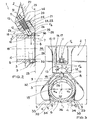
- FIG. 2 shows the clamping flange assembly 1 in cross section.
- the abutment 13 is arranged with the bolt 11 encompassing GegenlagerausEnglishung 14, wherein in the abutment 13, the in FIG. 1 described bearing element 12 is pivotally mounted about the pivot axis 18.
- a blind recess 20 is formed in the abutment 13, which is the bearing element 12, as to FIG. 1 described, at least partially cylindrical, in particular designed as a section of a circular cylinder, with its bearing element rear side circumferentially at least partially surrounds and thus allows a defined arrangement in the abutment 13.
- a thread 22 is provided as an internal thread 23, which corresponds to an external thread 24 in a preferably central region 25 in the longitudinal extension of the bolt 11.
- the bolt 11 can therefore be adjusted longitudinally in the thread 22 by axial rotation, resulting in a change in the length of his from the bearing element 12 exiting bottom pressure end 26.
- the threaded bolt 11 is unscrewed from the thread 22, for example by means of a tool engaging element formed at its head end 27 opposite the printing end, then the threaded bolt 11 is moved away from the clamping flange 8 formed on the pipe 6; however, if it is screwed into the thread 22, it is moved to the clamping flange 8 until it touches the Beaufschlagungs Suite 10 of the clamping flange and applied with a force F s .
- the clamping flange 8 is separated by vectoring of the force F S with its flange region 5 arranged opposite to the loading region 10 into the undercut 4 of the wall recess 3 arranged on the internal combustion engine 2, on the other hand in the direction of the extreme end of the end region 7 of the tube 6 is pressed to the internal combustion engine 2.
- the internal combustion engine 2 has a pipe support surface 28, with the pipe support surface 28 and end region 7 of the pipe 6 facing one another in a sealing plane 29 in contact position.
- the pipe support surface 28 is traversed for the passage of exhaust gases with a gas exchange channel 30, which opens into the pipe 6.
- the force F S is applied along a bolt longitudinal axis 31, which defines a clamping plane 36 with the pivot axis 18, which forms an angle of 90 ° with the sealing plane 29.
- the clamping plane 36 In rest position (ie in particular in the cold state of the internal combustion engine 2 and the pipe 6), the clamping plane 36 extends through a center 37 of the tube 6 in the region of the clamping flange 8. In the loading region 10, it is vectorial division into the sealing force F D and in the Flanschklemmkraft F F disassembled.
- the sealing force F D presses the end portion 7 of the tube 6 to the pipe support surface 28, in the sealing plane 29; the Flanschklemmkraft F F presses the tube 6 with the flange 5 in the undercut 4. This ensures a secure, defined fit of the clamping flange 8 and thus of the tube 6 to the internal combustion engine 2 with optimal sealing in the sealing plane 29 with only one bolt 27.
- FIG. 3 shows the clamping flange assembly 1 described above in cross section.
- the screwed into the bearing element 12 bolt 11 causes via its support in the bearing element 12 that in turn is supported on the abutment 13, an application of the Beaufschlagungs Kunststoffs 10 of the clamping flange 8 of the tube 6 with the force F S.
- the clamping flange 8 is arranged with the flange region 5 in the undercut 4 not visible here due to the perspective, the clamping flange 8 being able to carry out a horizontal displacement V H in the horizontal direction R H within the wall recess 3 formed on the internal combustion engine 2, in particular by thermal expansion of the pipe formed as a manifold 19 pipe 6.
- the force F S is introduced into the loading area 10 in the clamping flange 8, thereby characterized in that the bolt 11 in the bearing element 12, this is supported on the thrust bearing 13, an introduction of Supporting force F A through the bearing element 12 in the anvil 13.
- the pressure end 26 of the threaded bolt 11 has the same length, ie the bolt 11 remains unchanged in its axial position in the bearing element 12, a slight reduction in the loading area 10 results acting force F S.
- the bolt 11 is screwed in the rest position of the clamping flange 8 so far that the force F S leads to a bias of the tube 6 via the loading area 10.
- the tube 6, at least in the region of the clamping flange 8, consists of an elastic material 32;
- the flange portion 5 is here designed in the form of integrally formed to the tube 6 lugs 33, wherein the lugs 33 are executed with their nasal base 34 parallel to the undercut. This results in the interaction of flange 5 and undercut 4 a rotation 35 with respect to the tube 6 in its arrangement in the wall recess. 3
Landscapes
- Engineering & Computer Science (AREA)
- General Engineering & Computer Science (AREA)
- Mechanical Engineering (AREA)
- Chemical & Material Sciences (AREA)
- Combustion & Propulsion (AREA)
- Exhaust Silencers (AREA)
- Cylinder Crankcases Of Internal Combustion Engines (AREA)
- Clamps And Clips (AREA)
- Exhaust Gas After Treatment (AREA)
- Flanged Joints, Insulating Joints, And Other Joints (AREA)
Description
- Die Erfindung betrifft eine Klemmflanschanordnung zum Anschluss einer Auspuffanlage an eine Brennkraftmaschine nach Oberbegriff des Anspruchs 1.
- Klemmflanschanordnungen zum Anschluss von Auspuffanlagen an Brennkraftmaschinen sind bekannt. Sie dienen dazu, eine Verbindung von Auspuffrohren, insbesondere von Auspuffkrümmern, mit Gasauslasskanälen der Brennkraftmaschine bereitzustellen, wobei diese Krümmer eine hohe thermische Belastung durch die heißen Abgase der Brennkraftmaschine erfahren. Die durch thermische Belastung erfolgende Dimensionsänderung des Krümmers und/oder eines Auslassbereiches der Brennkraftmaschine muss von der Klemmflanschanordnung in einer solchen Art und Weise aufgenommen werden, dass die Verbindung dicht bleibt. Gleichzeitig ist eine einfache Montage und/oder Demontage gewünscht. Hierzu ist beispielsweise aus der
DE 42 05 454 A1 eine Einrichtung zum Anschließen eines Rohrkrümmers an einen Zylinderkopf bekannt, bei der der Rohrkrümmer mittels eines Klemmflansches im Bereich des Auslasskanals der Brennkraftmaschine angeordnet ist und über eine quer zur Dichtfläche eine Oberseite des Krümmers kraftbeaufschlagende Schraube gehalten wird, die sich mit ihrem Gewinde in einem einstückig zum Motorblock ausgebildeten Innengewinde abstützt. Bei dieser und anderen bekannten Anordnungen ist nachteilig, dass die durch die Wärmedehnung insbesondere des Krümmers relativ zum Motorblock der Brennkraftmaschine erfolgende Längenänderung zu einer Querkraft im Bereich der den Krümmer haltenden Schraube und/oder zu Verformungen des Krümmers und/oder eines freien Bereichs der Schraube führt. Weiter ist nachteilig, dass diese Anordnung zur Verzunderung neigt, da einerseits die im Regelfall verwendeten Materialien, nämlich Aluminium für den Motorblock der Brennkraftmaschine und Stahl für die den Krümmer haltende Schraube, in dieser Kombination zur Korrosion neigen und durch die starke thermische Einwirkung eine Verzunderung erfolgt, so dass die den Krümmer klemmende Schraube nach langen Betriebsjahren der Brennkraftmaschine nur noch sehr schwer gelöst werden kann. - Aufgabe der Erfindung ist es, eine Klemmflanschanordnung zum Anschluss einer Auspuffanlage an eine Brennkraftmaschine bereitzustellen, die die genannten Nachteile vermeidet.
- Hierzu wird eine Klemmflanschanordnung zum Anschluss einer Auspuffanlage an eine Brennkraftmaschine vorgeschlagen, mit mindestens einer an der Brennkraftmaschine ausgebildeten Hinterschneidung, in der ein .Flanschbereich eines Klemmflansches eingesetzt angeordnet ist und mit mindestens einem Schraubbolzen, der in ein der Brennkraftmaschine zugeordnetes Gewinde eingeschraubt ist und mit einem Ende den Klemmflansch oder ein am Klemmflansch befestigtes Rohr, insbesondere Krümmerrohr, der Auspuffanlage klemmend beaufschlagt. Hierbei ist vorgesehen, dass das Gewinde in einem Lagerelement ausgebildet ist, das sich an einem Gegenlager der Brennkraftmaschine verlagerbar abstützt. Der Schraubbolzen, der, ähnlich den im Stand der Technik bekannten Ausführungen, das Krümmerrohr klemmend beaufschlagt, ist demnach in einem Gewinde geführt, das in einem Lagerelement ausgebildet und hierbei um Querkräfte und Verformungen durch die thermisch bedingte Dimensionsänderung insbesondere des Krümmerrohrs, aber auch der Brennkraftmaschine, insbesondere des Motorblocks, aufzufangen, verlagerbar angeordnet ist. Das Gewinde, in dem der Schraubbolzen geführt ist, ist daher nicht fest, insbesondere nicht einstückig mit dem Zylinderkopf der Brennkraftmaschine ausgebildet, sondern kann sich relativ zu diesem oder zur Brennkraftmaschine als solcher verlagern.
- In einer bevorzugten Ausführungsform ist vorgesehen, dass das Lagerelement ein Schwenklagerelement ist. Ein Schwenklagerelement ist ein solches Lagerelement, das sich um eine Schwenkachse verschwenken lässt.
- In einer anderen Ausführungsform ist vorgesehen, dass das Lagerelement ein Schiebelagerelement ist. Ein Schiebelagerelement lässt sich in einer quer zur Längserstreckung des Schraubbolzens verlaufenden Schiebeebene verschieben, insbesondere gleitend verschieben.
- Es ist weiter vorgesehen, dass der Klemmflansch in einer Dichtebene an der Brennkraftmaschine anliegt. Zwischen dem Klemmflansch und der Brennkraftmaschine ist folglich eine Ebene ausgebildet, in der sich Klemmflansch und Brennkraftmaschine in Berührlage befinden, und in der die Abdichtung erfolgt.
- In einer weiteren bevorzugten Ausführungsform ist vorgesehen, dass das Lagerelement um eine Schwenkachse verschwenkbar ist, die quer zu einer Schraubbolzenlängsachse des Schraubbolzens verläuft sowie die Schraubbolzenlängsachse kreuzt und in einer Klemmebene liegt, in der die Schraubbolzenlängsachse liegt, wobei die Klemmebene zu der Dichtebene einen Winkel von 90° einschließt. Das Lagerelement weist demzufolge eine Schwenkachse auf, um die es verschwenkbar ist. Diese liegt quer zur Schraubbolzenlängsachse des Schraubbolzens und kreuzt hierbei die Schraubbolzenlängsachse. Die Schwenkachse liegt weiter in einer Klemmebene, in der auch die Schraubenbolzenachse liegt, wobei die Klemmebene zu der Dichtebene einen Winkel von 90° einschließt.
- In einer weiteren bevorzugten Ausführungsform ist vorgesehen, dass die Klemmebene durch oder im Wesentlichen durch ein Zentrum des an die Brennkraftmaschine mittels des Klemmflansches angeschlossenen Rohres, insbesondere Krümmerrohrs, der Auspuffanlage verläuft. Hiermit ist gemeint, dass die Klemmebene als die Ebene, in der die von dem Schraubbolzen aufgebrachte Klemmkraft an das Rohr, insbesondere das Krümmerrohr, angreift, durch das Zentrum eben dieses Rohres, betrachtet in der Nähe der Brennkraftmaschine, verläuft. Hiermit ist auch gemeint, dass, insbesondere durch Wärmeausdehnung und thermische Dimensionsänderung bedingt, es nicht erforderlich ist, dass die Klemmebene genau durch das Zentrum des angeschlossenen Rohres verläuft. Bewegt sich beispielsweise das Rohr durch Wärmeausdehnung im Betrieb mit heißen Gasen um eine kleine Strecke in die eine oder andere Richtung, was insbesondere bei am Motorblock außenliegenden (also ersten oder letzten) Rohren gut zu beobachten ist, ergibt sich hierdurch ein Verlauf der Klemmebene, der nicht genau durch das Zentrum des Rohres geht, sondern um eben diese Strecke exzentrisch ist.
- In einer anderen Ausführungsform ist vorgesehen, dass das Schiebelagerelement entlang einer Verschieberichtung verlagerbar ist, die mit der Klemmebene einen Winkel von 90° einschließt. In der Klemmebene (oder im Wesentlichen in der Klemmebene) erfolgt die Kraftbeaufschlagung durch den Schraubbolzen, wobei in der Verschieberichtung die durch thermische Dimensionsänderung, insbesondere Längenänderung, bewirkte Verschiebung des jeweiligen Rohres relativ zu der Brennkraftmaschine erfolgt. Das Schiebelagerelement ist genau entlang dieser Verschieberichtung verlagerbar, so dass die Längen- beziehungsweise Dimensionsänderung des Rohres mitgemacht werden kann, ohne dass sich der Kraftangriff des Schraubbolzens relativ zum Rohr nachteilig verändert.
- Weiter ist vorgesehen, dass der Schraubbolzen auf einer Seite des Klemmflansches liegt und dass der Flanschbereich auf einer zu dieser Seite gegenüberliegenden Seite des Klemmflansches angeordnet ist. Der Klemmflansch ist hierbei insbesondere als Endbereich des Rohres ausgebildet, wobei der Schraubbolzen an der einen Seite des Klemmflansches liegt beziehungsweise angreift, wohingegen der Flanschbereich, der in der Hinterschneidung eingesetzt angeordnet ist, auf der dieser gegenüberliegenden Seite des Klemmflansches angeordnet ist. Auf diese Weise ergibt sich eine im Wesentlichen zentrisch durch das Rohr verlaufende Kraftbeaufschlagung mit einer gleichmäßigen Kräftezerlegung und Klemmwirkung bei Kraftbeaufschlagung mit nur einem Schraubbolzen.
- In einer weiteren Ausführungsform ist vorgesehen, dass das Rohr, insbesondere Krümmerrohr, elastisch nachgiebig, insbesondere zumindest im Beaufschlagungsbereich des Schraubbolzens elastisch nachgiebig, ausgebildet ist. Durch Wahl geeigneter Werkstoffe lässt sich die Elastizität, insbesondere die elastische Verformbarkeit des Rohres weitgehend frei bestimmen. Durch diese elastische Ausbildung des Rohres kann die Vorspannkraft im Beaufschlagungsbereich des Schraubbolzens weitgehend frei bestimmt werden. Hierdurch ergibt sich auch bei thermisch bedingter Dimensionsänderung des Rohres eine für eine sichere, dichte Klemmverbindung stets ausreichende Vorspannkraft. Diese wird auch nicht durch das Verschwenken des Schraubbolzens in dem Schwenklagerelement nachteilig beeinträchtigt. Zwar bewirkt ein Verschwenken um die Schwenkachse eine Längenänderung der Strecke zwischen Schwenkachse und Beaufschlagungsbereich, wobei der Schraubbolzen selbstverständlich diese Längenänderung nicht mitmacht, sondern in seiner Länge unverändert bleibt. Die sich hieraus ergebende Längendifferenz wird aber durch die Vorspannkraft, die durch die elastische Ausbildung des Rohres bewirkt wird, ohne Nachteile ausgeglichen.
- In einer weiteren, bevorzugten Ausführungsform bildet der Flanschbereich zusammen mit der Hinterschneidung eine Verdrehsicherung für das Rohr, insbesondere Krümmerrohr. Der Flanschbereich und die zu diesem korrespondierende Hinterschneidung sind hierbei so ausgebildet, dass sie, beispielsweise durch die Ausbildung von Nasen oder tangential zum Rohr verlaufenden Auflagebereichen, relativ zur Brennkraftmaschine eine Verdrehung des Rohres um sein Zentrum oder einen Drehpunkt außerhalb des Zentrum nicht zulassen. Insbesondere kann der Flanschbereich als einstückig zum Rohr rohraußenumfangsseitig angeordnete, tangentiale, einseitige Auflagefläche ausgebildet sein.
- Weitere vorteilhafte Ausführungsformen ergeben sich aus den Unteransprüchen und aus Kombinationen derselben.
- Die Erfindung wird nachfolgend anhand von Figuren näher erläutert.
- Es zeigen
- Figur 1
- eine dreidimensionale Darstellung einer erfindungsgemäßen Klemmflanschanordnung;
- Figur 2
- einen Längsschnitt durch eine erfindungsgemäße Klemmflanschanordnung und
- Figur 3
- einen Querschnitt durch eine erfindungsgemäße Klemmflanschanordnung.
-
Figur 1 zeigt eine Klemmflanschanordnung 1 einer nicht dargestellten Auspuffanlage einer nur ausschnittsweise dargestellten Brennkraftmaschine 2. An der Brennkraftmaschine 2 ist in einer Übergröße aufweisenden Wandausnehmung 3 unterseitig eine Hinterschneidung 4 angeordnet, die mit einem Flanschbereich 5, der an einem Rohr 6 unterseitig ausgebildet ist, zusammenwirkt. Das Rohr 6, an dem der Flanschbereich 5 einstückig ausgebildet ist, ist mit einem, in Axialerstreckung betrachteten, der Brennkraftmaschine 2 zugewandten Endbereich 7 der Brennkraftmaschine 2 angelagert. Der Endbereich 7 bildet hierbei einen Klemmflansch 8 aus, der an seiner dem Flanschbereich 5 gegenüberliegenden Oberseite 9 einen Beaufschlagungsbereich 10 aufweist, der von einem Schraubbolzen 11 beaufschlagt wird. Der Schraubbolzen 11 ist in einem der Brennkraftmaschine 2 zugeordneten, hier nicht sichtbaren Gewinde eingeschraubt, das in einem Lagerelement 12 ausgebildet ist, das sich an einem dem Flanschbereich 5 gegenüberliegenden, an der Brennkraftmaschine 2 ausgebildeten Gegenlager 13 abstützt. Der Schraubbolzen 11 durchgreift hierzu eine in das Gegenlager 13 eingebrachte Gegenlagerausnehmung 14, die relativ zu dem Durchmesser des Schraubbolzens 11 deutliches Übermaß besitzt, um ein Radialspiel des Schraubbolzens 11 in der Gegenlagerausnehmung 14 zu erlauben. Das Lagerelement 12 ist mit seiner dem Rohr 6 abgewandten, dem Gegenlager 13 zugewandten Lagerelementeoberseite 15 als Abschnitt eines Kreiszylinders ausgebildet, dergestalt, dass die Lagerelementeoberseite 15 wie eine Mantelfläche eines Kreiszylinders gestaltet ist. Das Lagerelement 12 hat demzufolge einen halbkreisförmigen oder fast halbkreisförmigen Querschnitt. Das Gegenlager 13 weist mit seiner Gegenlagerunterseite 16 eine diesem entsprechende, formangepasste Geometrie auf. Lagerelementeoberseite 15 und Gegenlagerunterseite 16 bilden hierbei Gleitflächen 17 aus. Das Lagerelement 12 ist somit vermittels der Gleitflächen 17 um eine Schwenkachse 18 verschwenkbar. Da die Wandausnehmung 3 relativ zum Klemmflansch 8 Übergröße aufweist, kann das Rohr 6 in Horizontalrichtung RH eine Horizontalbewegung in geringem Umfange ausführen, wobei das Lagerelement 12 über den Schraubbolzen 11 von einer durch diese Verschiebung bewirkten Querkraft Q beaufschlagt und hierdurch um die Schwenkachse 18 verschwenkt wird, wobei sich das Lagerelement 12 an dem Gegenlager 13 über die Lagerelementeoberseite 15 und die Gegenlagerunterseite 16, nämlich die Gleitflächen 17, gleitend abstützt. Insbesondere thermische Ausdehnung des Rohrs 6, das insbesondere als Krümmerrohr 19 ausgebildet ist, kann hierdurch bei gleichbleibend gut dichtender Anpressung durch den Schraubbolzen 11 an die Brennkraftmaschine 2 ausgeglichen werden. -
Figur 2 zeigt die Klemmflanschanordnung 1 im Querschnitt. An der Brennkraftmaschine 2 ist das Gegenlager 13 mit der den Schraubbolzen 11 umgreifenden Gegenlagerausnehmung 14 angeordnet, wobei in dem Gegenlager 13 das inFigur 1 beschriebene Lagerelement 12 um die Schwenkachse 18 verschwenkbar angeordnet ist. Hierzu ist in dem Gegenlager 13 eine Sackausnehmung 20 ausgebildet, die das Lagerelement 12, das wie zuFigur 1 beschrieben, wenigstens teilweise zylindrisch, insbesondere als Abschnitt eines Kreiszylinders ausgeführt ist, mit seiner Lagerelementrückseite umfangsseitig wenigstens abschnittsweise umgreift und somit eine definierte Anordnung in dem Gegenlager 13 ermöglicht. In dem Lagerelement 12 ist ein Gewinde 22 als Innengewinde 23 vorgesehen, dem ein Außengewinde 24 in einem bevorzugt mittleren Bereich 25 in Längserstreckung des Schraubbolzens 11 entspricht. Der Schraubbolzen 11 kann demzufolge in dem Gewinde 22 durch axiales Verdrehen längsverstellt werden, wodurch sich eine Änderung der Länge seines aus dem Lagerelement 12 unterseitig austretenden Druckendes 26 ergibt. Wird der Schraubbolzen 11 aus dem Gewinde 22 herausgeschraubt, beispielsweise mittels eines an seinem dem Druckende gegenüberliegenden Kopfende 27 ausgebildeten Werkzeugeingriffselements, so wird der Schraubbolzen 11 von dem an dem Rohr 6 ausgebildeten Klemmflansch 8 wegbewegt; wird er hingegen in das Gewinde 22 eingeschraubt, wird er auf den Klemmflansch 8 zugbewegt, bis er den Beaufschlagungsbereich 10 des Klemmflansches berührt und mit einer Kraft Fs beaufschlagt. Durch die Beaufschlagung mit der Kraft FS wird der Klemmflansch 8 durch Vektorzerlegung der Kraft FS einerseits mit seinem gegenüber dem Beaufschlagungsbereich 10 angeordneten Flanschbereich 5 in die Hinterschneidung 4 der an der Brennkraftmaschine 2 angeordneten Wandausnehmung 3, andererseits in Richtung auf das äußerste Ende des Endbereichs 7 des Rohres 6 an die Brennkraftmaschine 2 gepresst. Die Brennkraftmaschine 2 weist hierzu eine Rohrauflagefläche 28 auf, wobei Rohrauflagefläche 28 und Endbereich 7 des Rohres 6 einander in einer Dichtebene 29 in Berührlage gegenüberliegen. Die Rohrauflagefläche 28 ist für den Durchtritt von Auspuffgasen mit einem Gaswechselkanal 30 durchsetzt, der in das Rohr 6 mündet. Zwischen der Rohrauflagefläche 28 und dem Endbereich 7 des Rohres 6 kann vorteilhaft eine hier nicht dargestellte Dichtung angeordnet sein, die aufgrund ihrer Materialeigenschaften eine bessere Abdichtung zwischen Rohr 6 und Rohrauflagefläche 28 bewirkt. Die Kraft FS wird entlang einer Schraubbolzenlängsachse 31 aufgebracht, die mit der Schwenkachse 18 eine Klemmebene 36 definiert, die mit der Dichtebene 29 einen Winkel von 90° einschließt. In Ruhelage (insbesondere also im kalten Zustand der Brennkraftmaschine 2 und des Rohres 6) verläuft die Klemmebene 36 durch ein Zentrum 37 des Rohres 6 im Bereich des Klemmflansches 8. Im Beaufschlagungsbereich 10 wird sie durch vektorielle Zerteilung in die Dichtpresskraft FD sowie in die Flanschklemmkraft FF zerlegt. Die Dichtpresskraft FD presst den Endbereich 7 des Rohrs 6 an die Rohrauflagefläche 28, und zwar in der Dichtebene 29; die Flanschklemmkraft FF presst das Rohr 6 mit dem Flanschbereich 5 in die Hinterschneidung 4. Hierdurch wird ein sicherer, definierter Sitz des Klemmflansches 8 und damit des Rohres 6 an der Brennkraftmaschine 2 bei optimaler Abdichtung in der Dichtebene 29 mit nur einem Schraubbolzen 27 bewirkt. -
Figur 3 zeigt die vorstehend beschriebene Klemmflanschanordnung 1 im Querschnitt. Der in dem Lagerelement 12 eingeschraubte Schraubbolzen 11 bewirkt über seine Abstützung in dem Lagerelement 12, dass sich seinerseits am Gegenlager 13 abstützt, eine Beaufschlagung des Beaufschlagungsbereichs 10 des Klemmflansches 8 des Rohres 6 mit der Kraft FS. Der Klemmflansch 8 ist mit dem Flanschbereich 5 in der aufgrund der Perspektive hier nicht sichtbaren Hinterschneidung 4 eingesetzt angeordnet, wobei der Klemmflansch 8 innerhalb der Wandausnehmung 3, die an der Brennkraftmaschine 2 ausgebildet ist, eine Horizontalverschiebung VH in Horizontalrichtung RH durchführen kann, insbesondere durch thermische Ausdehnung des als Krümmerrohr 19 ausgebildeten Rohres 6. Die Kraft FS wird im Beaufschlagungsbereich 10 in den Klemmflansch 8 eingeleitet, wodurch sich dadurch, dass sich der Schraubbolzen 11 in dem Lagerelement 12, dieses sich an dem Gegenlager 13 abstützt, eine Einleitung von Abstützkraft FA durch das Lagerelement 12 in das Gegenlager 13. Weiter ergibt sich eine Einleitung der Flanschklemmkraft FF über die Hinterschneidung 4 in die Brennkraftmaschine 2. Durch die geringfügige Horizontalverschiebung VH wird das Lagerelement 12 um die Schwenkachse 18 verschwenkt, wobei es sich nach wie vor an dem Gegenlager 13 abstützt, wie zuvor inFigur 1 undFigur 2 beschrieben. Da durch diese Verschwenkbewegung der Abstand d zwischen Lagerelement 12 und Beaufschlagungsbereich 10 geringfügig größer wird, das Druckende 26 des Schraubbolzens 11 aber längengleich, der Schraubbolzen 11 also unverändert hinsichtlich seiner Axiallage in dem Lagerelement 12 verbleibt, ergibt sich eine geringfügige Reduktion der auf den Beaufschlagungsbereich 10 einwirkenden Kraft FS. Um dies zufriedenstellend auszugleichen, wird der Schraubbolzen 11 in Ruhelage des Klemmflansches 8 so weit eingeschraubt, dass die Kraft FS zu einer Vorspannung des Rohres 6 über den Beaufschlagungsbereich 10 führt. Dies ist besonders vorteilhaft dadurch darstellbar, dass das Rohr 6, zumindest im Bereich des Klemmflansches 8, aus einem elastischen Werkstoff 32 besteht; über geeignete Werkstoffauswahl kann insbesondere durch Legierung von geeigneten Metallen eine solche zu guter Vorspannung führende Elastizität problemlos bewirkt werden. Der Flanschbereich 5 ist hier in Form von einstückig zum Rohr 6 ausgebildeten Nasen 33 ausgeführt, wobei die Nasen 33 mit ihrer Nasenunterseite 34 parallel zur Hinterschneidung ausgeführt sind. Hierdurch ergibt sich im Zusammenwirken von Flanschbereich 5 und Hinterschneidung 4 eine Verdrehsicherung 35 hinsichtlich des Rohres 6 in seiner Anordnung in der Wandausnehmung 3. -
- 1
- Klemmflanschanordnung
- 2
- Brennkraftmaschine
- 3
- Wandausnehmung
- 4
- Hinterschneidung
- 5
- Flanschbereich
- 6
- Rohr
- 7
- Endbereich
- 8
- Klemmflansch
- 9
- Oberseite
- 10
- Beaufschlagungsbereich
- 11
- Schraubbolzen
- 12
- Lagerelement
- 13
- Gegenlager
- 14
- Gegenlagerausnehmung
- 15
- Lagerelementeoberseite
- 16
- Gegenlagerunterseite
- 17
- Gleitfläche
- 18
- Schwenkachse
- 19
- Krümmerrohr
- 20
- Sackausnehmung
- 21
- Lagerelementrückseite
- 22
- Gewinde
- 23
- Innengewinde
- 24
- Außengewinde
- 25
- mittlerer Bereich
- 26
- Druckende
- 27
- Kopfende
- 28
- Rohrauflagefläche
- 29
- Dichtebene
- 30
- Gaswechselkanal
- 31
- Schraubbolzenlängsachse
- 32
- elastischer Werkstoff
- 33
- Nase
- 34
- Nasenunterseite
- 35
- Verdrehsicherung
- 36
- Klemmebene
- 37
- Zentrum
- RH
- Horizontalrichtung
- Q
- Querkraft
- FS
- Kraft
- FD
- Dichtpresskraft
- FF
- Flanschklemmkraft
- FA
- Abstützkraft
- VH
- Horizontalverschiebung
- d
- Abstand
Claims (10)
- Klemmflanschanordnung zum Anschluss einer Auspuffanlage an eine Brennkraftmaschine, mit mindestens einer an der Brennkraftmaschine ausgebildeten Hinterschneidung, in der ein Flanschbereich eines Klemmflansches eingesetzt angeordnet ist und mit mindestens einem Schraubbolzen, der in ein der Brennkraftmaschine zugeordnetes Gewinde eingeschraubt ist und mit einem Ende den Klemmflansch oder ein am Klemmflansch befestigtes Rohr, insbesondere Krümmerrohr, der Auspuffanlage klemmend beaufschlagt, dadurch gekennzeichnet, dass das Gewinde (22) in einem Lagerelement (12) ausgebildet ist, das sich an einem Gegenlager (13) der Brennkraftmaschine (2) verlagerbar abstützt.
- Klemmflanschanordnung nach Anspruch 1, dadurch gekennzeichnet, dass das Lagerelement (12) ein Schwenklagerelement ist.
- Klemmflanschanordnung nach einem der vorhergehenden Ansprüche, dadurch gekennzeichnet, dass das Lagerelement (12) ein Schiebelagerelement ist.
- Klemmflanschanordnung nach einem der vorhergehenden Ansprüche, dadurch gekennzeichnet, dass der Klemmflansch (8) in einer Dichtebene (29) an der Brennkraftmaschine (2) anliegt.
- Klemmflanschanordnung nach einem der vorhergehenden Ansprüche, dadurch gekennzeichnet, dass das Lagerelement (12) um eine Schwenkachse (18) verschwenkbar ist, die quer zu einer Schraubbolzenlängsachse (31) des Schraubbolzens (11) verläuft sowie die Schraubbolzenlängsachse (31) kreuzt und in einer Klemmebene (36) liegt, in der die Schraubenbolzenachse (31) liegt, wobei die Klemmebene (36) zu der Dichtebene (29) einen Winkel von 90° einschließt.
- Klemmflanschanordnung nach einem der vorhergehenden Ansprüche, dadurch gekennzeichnet, dass die Klemmebene (36) durch oder im Wesentlichen durch ein Zentrum (37) des an die Brennkraftmaschine (2) mittels des Klemmflansches (8) angeschlossenen Rohrs (6), insbesondere Krümmerrohrs (19), der Auspuffanlage verläuft.
- Klemmflanschanordnung nach einem der vorhergehenden Ansprüche, dadurch gekennzeichnet, dass das Schiebelagerelement entlang einer Verschieberichtung verlagerbar ist, die mit der Klemmebene (36) einen Winkel von 90° einschließt.
- Klemmflanschanordnung nach einem der vorhergehenden Ansprüche, dadurch gekennzeichnet, dass der Schraubbolzen (11) auf einer Seite des Klemmflansches (8) liegt und dass der Flanschbereich (5) auf einer zu dieser Seite gegenüberliegenden Seite des Klemmflansches (8) angeordnet ist.
- Klemmflanschanordnung nach einem der vorhergehenden Ansprüche, dadurch gekennzeichnet, dass das Rohr (6), insbesondere Krümmerrohr (19), elastisch nachgiebig, insbesondere zumindest im Beaufschlagungsbereich (10) des Schraubbolzens (11) elastisch nachgiebig, ausgebildet ist.
- Klemmflanschanordnung nach einem der vorhergehenden Ansprüche, dadurch gekennzeichnet, dass der Flanschbereich (5) zusammen mit der Hinterschneidung (4) eine Verdrehsicherung (35) für das Rohr (6), insbesondere Krümmerrohr (19), bildet.
Applications Claiming Priority (2)
| Application Number | Priority Date | Filing Date | Title |
|---|---|---|---|
| DE102007002825A DE102007002825B4 (de) | 2007-01-19 | 2007-01-19 | Klemmflanschanordnung zum Anschluss einer Auspuffanlage an eine Brennkraftmaschine |
| PCT/EP2008/000246 WO2008087001A1 (de) | 2007-01-19 | 2008-01-15 | Klemmflanschanordnung zum anschluss einer auspuffanlage an eine brennkraftmaschine |
Publications (2)
| Publication Number | Publication Date |
|---|---|
| EP2115281A1 EP2115281A1 (de) | 2009-11-11 |
| EP2115281B1 true EP2115281B1 (de) | 2010-03-24 |
Family
ID=39166414
Family Applications (1)
| Application Number | Title | Priority Date | Filing Date |
|---|---|---|---|
| EP08701106A Not-in-force EP2115281B1 (de) | 2007-01-19 | 2008-01-15 | Klemmflanschanordnung zum anschluss einer auspuffanlage an eine brennkraftmaschine |
Country Status (7)
| Country | Link |
|---|---|
| US (1) | US8201400B2 (de) |
| EP (1) | EP2115281B1 (de) |
| JP (1) | JP5208129B2 (de) |
| CN (1) | CN101558223B (de) |
| AT (1) | ATE462067T1 (de) |
| DE (2) | DE102007002825B4 (de) |
| WO (1) | WO2008087001A1 (de) |
Families Citing this family (13)
| Publication number | Priority date | Publication date | Assignee | Title |
|---|---|---|---|---|
| DE102007002825B4 (de) | 2007-01-19 | 2008-12-11 | Audi Ag | Klemmflanschanordnung zum Anschluss einer Auspuffanlage an eine Brennkraftmaschine |
| DE102009015481B4 (de) * | 2009-03-28 | 2013-09-05 | Audi Ag | Klemmflanschanordnung |
| AT509691B1 (de) | 2010-03-18 | 2013-09-15 | Avl List Gmbh | Brennkraftmaschine mit einer verbindungsanordnung für einen zylinderkopf |
| AT509689B1 (de) | 2010-03-18 | 2015-02-15 | Avl List Gmbh | Zylinderkopf-abgassammleranordnung |
| AT509690B1 (de) | 2010-03-18 | 2013-10-15 | Avl List Gmbh | Brennkraftmaschine mit einer verbindungsanordnung für einen zylinderkopf |
| AT508409B1 (de) | 2010-06-24 | 2013-09-15 | Avl List Gmbh | Brennkraftmaschine mit einer verbindungsanordnung für einen zylinderkopf |
| DE102011009340A1 (de) * | 2011-01-25 | 2012-07-26 | GM Global Technology Operations LLC (n. d. Ges. d. Staates Delaware) | Befestigungseinrichtung zur Befestigung eines Abgaskrümmers mit einem Zylinderkopf |
| DE102011017315B4 (de) * | 2011-04-16 | 2013-07-11 | Audi Ag | Steckkupplung für medienführende Leitungen mit zwei unter beengten Bedingungen verbindbaren Kupplungselementen |
| WO2014000866A1 (de) * | 2012-06-26 | 2014-01-03 | Deutz Aktiengesellschaft | Brennkraftmaschine mit abstandhülse mit mittenzentrierung |
| US20160326939A1 (en) * | 2013-12-13 | 2016-11-10 | Ab Volvo Penta | An internal combustion engine fastening arrangement, method and component |
| SE539990C2 (en) * | 2016-06-08 | 2018-02-20 | Scania Cv Ab | An arrangement for mounting a device to a vehicle beam |
| FR3094783B1 (fr) * | 2019-04-05 | 2021-02-26 | Renault Sas | Dispositif de fixation en oblique sur culasse |
| CN112145275A (zh) * | 2020-09-30 | 2020-12-29 | 东风商用车有限公司 | 一种新型带限位结构的装配式排气管 |
Family Cites Families (14)
| Publication number | Priority date | Publication date | Assignee | Title |
|---|---|---|---|---|
| FR2218777A5 (de) * | 1973-02-16 | 1974-09-13 | Peugeot & Renault | |
| JPH0629549B2 (ja) * | 1985-07-23 | 1994-04-20 | ヤマハ発動機株式会社 | エンジンの排気管連結装置 |
| DE4205454A1 (de) | 1992-02-22 | 1993-08-26 | H J Kuepper Gmbh & Co Kg | Einrichtung zum anschliessen eines rohrkruemmers an einen zylinderkopf |
| DE4338719A1 (de) | 1993-11-12 | 1995-05-18 | Bischoff Erhardt Gmbh Co Kg | Flanschverbindung |
| DE4430339A1 (de) * | 1993-11-12 | 1996-02-29 | Bischoff Erhardt Gmbh Co Kg | Anordnung zur Flanschverbindung |
| DE4413488A1 (de) * | 1994-04-19 | 1995-10-26 | Leybold Ag | Vakuumdichte Verbindung |
| DE19516375A1 (de) * | 1995-05-04 | 1996-11-07 | Payen Goetze Gmbh | Metallische Flachdichtung |
| DE19653908A1 (de) * | 1996-12-21 | 1998-06-25 | Daimler Benz Ag | Einrichtung zum Anschluß eines Rohrkrümmers |
| US6789386B1 (en) * | 1999-08-05 | 2004-09-14 | Hans A. Haerle | Exhaust gas manifold |
| DE10251771A1 (de) * | 2002-11-07 | 2004-06-03 | Adam Opel Ag | Zylinderkopf-Krümmer-Anordnung |
| JP2006183674A (ja) * | 2003-03-24 | 2006-07-13 | Koganei Corp | 長手方向締結具、長手方向締結組立体およびその締結方法 |
| DE102004010815A1 (de) * | 2004-03-05 | 2005-09-29 | Benteler Automobiltechnik Gmbh | Anordnung zur Fixierung eines Abgaskrümmers auf dem Zylinderkopf einer Brennkraftmaschine |
| FR2902458A1 (fr) * | 2006-06-20 | 2007-12-21 | Renault Sas | Agencement pour le raccordement par bridage d'un organe auxiliaire d'un moteur a combustion |
| DE102007002825B4 (de) | 2007-01-19 | 2008-12-11 | Audi Ag | Klemmflanschanordnung zum Anschluss einer Auspuffanlage an eine Brennkraftmaschine |
-
2007
- 2007-01-19 DE DE102007002825A patent/DE102007002825B4/de not_active Expired - Fee Related
-
2008
- 2008-01-15 EP EP08701106A patent/EP2115281B1/de not_active Not-in-force
- 2008-01-15 AT AT08701106T patent/ATE462067T1/de active
- 2008-01-15 JP JP2009545864A patent/JP5208129B2/ja not_active Expired - Fee Related
- 2008-01-15 CN CN2008800011051A patent/CN101558223B/zh not_active Expired - Fee Related
- 2008-01-15 WO PCT/EP2008/000246 patent/WO2008087001A1/de not_active Ceased
- 2008-01-15 US US12/523,597 patent/US8201400B2/en not_active Expired - Fee Related
- 2008-01-15 DE DE502008000476T patent/DE502008000476D1/de active Active
Also Published As
| Publication number | Publication date |
|---|---|
| CN101558223A (zh) | 2009-10-14 |
| US8201400B2 (en) | 2012-06-19 |
| JP5208129B2 (ja) | 2013-06-12 |
| ATE462067T1 (de) | 2010-04-15 |
| CN101558223B (zh) | 2011-10-12 |
| DE102007002825A1 (de) | 2008-07-24 |
| US20100078933A1 (en) | 2010-04-01 |
| DE502008000476D1 (de) | 2010-05-06 |
| EP2115281A1 (de) | 2009-11-11 |
| JP2010516931A (ja) | 2010-05-20 |
| WO2008087001A1 (de) | 2008-07-24 |
| DE102007002825B4 (de) | 2008-12-11 |
Similar Documents
| Publication | Publication Date | Title |
|---|---|---|
| DE102007002825B4 (de) | Klemmflanschanordnung zum Anschluss einer Auspuffanlage an eine Brennkraftmaschine | |
| EP0866221B1 (de) | Kraftstoffverteiler für einen Dieselmotor | |
| DE4116540C2 (de) | Abzweigverbindung in einer Hochdruck-Kraftstoffschiene | |
| EP1270891B1 (de) | Vorrichtung zur Befestigung eines Abgasturboladers an einem Abgaskrümmer einer Brennkraftmaschine | |
| EP1688654B1 (de) | Vakuumventil | |
| EP1888912B1 (de) | Anschluss-system | |
| DE102005022531B4 (de) | Verbindungsstruktur eines Zweig- bzw. Abzweigverbinders für gemeinsame Druckleitung | |
| CH697316B1 (de) | Leitapparat für eine Radialturbine. | |
| EP0758969B1 (de) | Zahnstangen-hilfskraftlenkung, insbesondere für kraftfahrzeuge | |
| DE20015016U1 (de) | Rohrheizpatrone | |
| EP1745210B1 (de) | Düsenbaugruppe und einspritzventil | |
| EP1502022A1 (de) | Kraftstoffverteilungsrohr für kraftfahrzeug-einspritzeinrichtungen, insbesondere für common-rail-systeme | |
| WO2011113790A1 (de) | Brennkraftmaschine mit einer verbindungsanordnung für einen zylinderkopf | |
| DE2744345C2 (de) | Rohr aus metallischem Werkstoff mit aus dem Rohrmaterial geformtem Anschlußende | |
| DE2332241B2 (de) | Rohrverbindung | |
| DE3822944C2 (de) | ||
| EP1979664B1 (de) | Spannschelle für hochdruck-schläuche | |
| EP2149024B1 (de) | Vorrichtung und verfahren zur befestigung einer mündungsbremse an einem waffenrohr | |
| DE19855795B4 (de) | Schneidringverschraubung für Druckmittel-Rohrleitungen | |
| DE19651659C1 (de) | Dichtungselement für eine Wanddurchführung | |
| EP1783413B1 (de) | Anordnung zum Verbinden des Endes eines schraubenlinienförmig gewellten Metallrohres mit einem Anschlussstück | |
| DE102005046913A1 (de) | Verbinder für Druckleitungen | |
| AT526935B1 (de) | Steckverbinder | |
| DE29701337U1 (de) | Anordnung zur Befestigung eines Gasgenerators, insbesondere eines Rohrgasgenerators in einem Gehäuse, insbesondere in einem Diffusor eines Airbagmoduls | |
| EP1273793B1 (de) | Schraubsicherung zur Drehblockierung eines Schraubteils |
Legal Events
| Date | Code | Title | Description |
|---|---|---|---|
| PUAI | Public reference made under article 153(3) epc to a published international application that has entered the european phase |
Free format text: ORIGINAL CODE: 0009012 |
|
| 17P | Request for examination filed |
Effective date: 20090819 |
|
| AK | Designated contracting states |
Kind code of ref document: A1 Designated state(s): AT BE BG CH CY CZ DE DK EE ES FI FR GB GR HR HU IE IS IT LI LT LU LV MC MT NL NO PL PT RO SE SI SK TR |
|
| GRAP | Despatch of communication of intention to grant a patent |
Free format text: ORIGINAL CODE: EPIDOSNIGR1 |
|
| GRAC | Information related to communication of intention to grant a patent modified |
Free format text: ORIGINAL CODE: EPIDOSCIGR1 |
|
| GRAS | Grant fee paid |
Free format text: ORIGINAL CODE: EPIDOSNIGR3 |
|
| GRAA | (expected) grant |
Free format text: ORIGINAL CODE: 0009210 |
|
| AK | Designated contracting states |
Kind code of ref document: B1 Designated state(s): AT BE BG CH CY CZ DE DK EE ES FI FR GB GR HR HU IE IS IT LI LT LU LV MC MT NL NO PL PT RO SE SI SK TR |
|
| REG | Reference to a national code |
Ref country code: GB Ref legal event code: FG4D Free format text: NOT ENGLISH |
|
| REG | Reference to a national code |
Ref country code: CH Ref legal event code: EP |
|
| REG | Reference to a national code |
Ref country code: IE Ref legal event code: FG4D |
|
| REF | Corresponds to: |
Ref document number: 502008000476 Country of ref document: DE Date of ref document: 20100506 Kind code of ref document: P |
|
| REG | Reference to a national code |
Ref country code: NL Ref legal event code: VDEP Effective date: 20100324 |
|
| PG25 | Lapsed in a contracting state [announced via postgrant information from national office to epo] |
Ref country code: LT Free format text: LAPSE BECAUSE OF FAILURE TO SUBMIT A TRANSLATION OF THE DESCRIPTION OR TO PAY THE FEE WITHIN THE PRESCRIBED TIME-LIMIT Effective date: 20100324 Ref country code: NO Free format text: LAPSE BECAUSE OF FAILURE TO SUBMIT A TRANSLATION OF THE DESCRIPTION OR TO PAY THE FEE WITHIN THE PRESCRIBED TIME-LIMIT Effective date: 20100624 Ref country code: HR Free format text: LAPSE BECAUSE OF FAILURE TO SUBMIT A TRANSLATION OF THE DESCRIPTION OR TO PAY THE FEE WITHIN THE PRESCRIBED TIME-LIMIT Effective date: 20100324 |
|
| LTIE | Lt: invalidation of european patent or patent extension |
Effective date: 20100324 |
|
| PG25 | Lapsed in a contracting state [announced via postgrant information from national office to epo] |
Ref country code: SI Free format text: LAPSE BECAUSE OF FAILURE TO SUBMIT A TRANSLATION OF THE DESCRIPTION OR TO PAY THE FEE WITHIN THE PRESCRIBED TIME-LIMIT Effective date: 20100324 Ref country code: PL Free format text: LAPSE BECAUSE OF FAILURE TO SUBMIT A TRANSLATION OF THE DESCRIPTION OR TO PAY THE FEE WITHIN THE PRESCRIBED TIME-LIMIT Effective date: 20100324 Ref country code: LV Free format text: LAPSE BECAUSE OF FAILURE TO SUBMIT A TRANSLATION OF THE DESCRIPTION OR TO PAY THE FEE WITHIN THE PRESCRIBED TIME-LIMIT Effective date: 20100324 Ref country code: FI Free format text: LAPSE BECAUSE OF FAILURE TO SUBMIT A TRANSLATION OF THE DESCRIPTION OR TO PAY THE FEE WITHIN THE PRESCRIBED TIME-LIMIT Effective date: 20100324 |
|
| REG | Reference to a national code |
Ref country code: IE Ref legal event code: FD4D |
|
| PG25 | Lapsed in a contracting state [announced via postgrant information from national office to epo] |
Ref country code: SE Free format text: LAPSE BECAUSE OF FAILURE TO SUBMIT A TRANSLATION OF THE DESCRIPTION OR TO PAY THE FEE WITHIN THE PRESCRIBED TIME-LIMIT Effective date: 20100324 Ref country code: ES Free format text: LAPSE BECAUSE OF FAILURE TO SUBMIT A TRANSLATION OF THE DESCRIPTION OR TO PAY THE FEE WITHIN THE PRESCRIBED TIME-LIMIT Effective date: 20100705 Ref country code: EE Free format text: LAPSE BECAUSE OF FAILURE TO SUBMIT A TRANSLATION OF THE DESCRIPTION OR TO PAY THE FEE WITHIN THE PRESCRIBED TIME-LIMIT Effective date: 20100324 Ref country code: GR Free format text: LAPSE BECAUSE OF FAILURE TO SUBMIT A TRANSLATION OF THE DESCRIPTION OR TO PAY THE FEE WITHIN THE PRESCRIBED TIME-LIMIT Effective date: 20100625 Ref country code: NL Free format text: LAPSE BECAUSE OF FAILURE TO SUBMIT A TRANSLATION OF THE DESCRIPTION OR TO PAY THE FEE WITHIN THE PRESCRIBED TIME-LIMIT Effective date: 20100324 Ref country code: RO Free format text: LAPSE BECAUSE OF FAILURE TO SUBMIT A TRANSLATION OF THE DESCRIPTION OR TO PAY THE FEE WITHIN THE PRESCRIBED TIME-LIMIT Effective date: 20100324 |
|
| PG25 | Lapsed in a contracting state [announced via postgrant information from national office to epo] |
Ref country code: IS Free format text: LAPSE BECAUSE OF FAILURE TO SUBMIT A TRANSLATION OF THE DESCRIPTION OR TO PAY THE FEE WITHIN THE PRESCRIBED TIME-LIMIT Effective date: 20100724 Ref country code: CZ Free format text: LAPSE BECAUSE OF FAILURE TO SUBMIT A TRANSLATION OF THE DESCRIPTION OR TO PAY THE FEE WITHIN THE PRESCRIBED TIME-LIMIT Effective date: 20100324 Ref country code: BG Free format text: LAPSE BECAUSE OF FAILURE TO SUBMIT A TRANSLATION OF THE DESCRIPTION OR TO PAY THE FEE WITHIN THE PRESCRIBED TIME-LIMIT Effective date: 20100624 Ref country code: SK Free format text: LAPSE BECAUSE OF FAILURE TO SUBMIT A TRANSLATION OF THE DESCRIPTION OR TO PAY THE FEE WITHIN THE PRESCRIBED TIME-LIMIT Effective date: 20100324 |
|
| PLBE | No opposition filed within time limit |
Free format text: ORIGINAL CODE: 0009261 |
|
| STAA | Information on the status of an ep patent application or granted ep patent |
Free format text: STATUS: NO OPPOSITION FILED WITHIN TIME LIMIT |
|
| PG25 | Lapsed in a contracting state [announced via postgrant information from national office to epo] |
Ref country code: DK Free format text: LAPSE BECAUSE OF FAILURE TO SUBMIT A TRANSLATION OF THE DESCRIPTION OR TO PAY THE FEE WITHIN THE PRESCRIBED TIME-LIMIT Effective date: 20100324 Ref country code: IE Free format text: LAPSE BECAUSE OF FAILURE TO SUBMIT A TRANSLATION OF THE DESCRIPTION OR TO PAY THE FEE WITHIN THE PRESCRIBED TIME-LIMIT Effective date: 20100324 |
|
| 26N | No opposition filed |
Effective date: 20101228 |
|
| BERE | Be: lapsed |
Owner name: AUDI A.G. Effective date: 20110131 |
|
| PG25 | Lapsed in a contracting state [announced via postgrant information from national office to epo] |
Ref country code: MC Free format text: LAPSE BECAUSE OF NON-PAYMENT OF DUE FEES Effective date: 20110131 |
|
| PG25 | Lapsed in a contracting state [announced via postgrant information from national office to epo] |
Ref country code: BE Free format text: LAPSE BECAUSE OF NON-PAYMENT OF DUE FEES Effective date: 20110131 |
|
| REG | Reference to a national code |
Ref country code: DE Ref legal event code: R119 Ref document number: 502008000476 Country of ref document: DE Effective date: 20110802 |
|
| PG25 | Lapsed in a contracting state [announced via postgrant information from national office to epo] |
Ref country code: MT Free format text: LAPSE BECAUSE OF FAILURE TO SUBMIT A TRANSLATION OF THE DESCRIPTION OR TO PAY THE FEE WITHIN THE PRESCRIBED TIME-LIMIT Effective date: 20100324 |
|
| REG | Reference to a national code |
Ref country code: CH Ref legal event code: PL |
|
| PG25 | Lapsed in a contracting state [announced via postgrant information from national office to epo] |
Ref country code: LI Free format text: LAPSE BECAUSE OF NON-PAYMENT OF DUE FEES Effective date: 20120131 Ref country code: CH Free format text: LAPSE BECAUSE OF NON-PAYMENT OF DUE FEES Effective date: 20120131 |
|
| PG25 | Lapsed in a contracting state [announced via postgrant information from national office to epo] |
Ref country code: LU Free format text: LAPSE BECAUSE OF NON-PAYMENT OF DUE FEES Effective date: 20110115 Ref country code: CY Free format text: LAPSE BECAUSE OF FAILURE TO SUBMIT A TRANSLATION OF THE DESCRIPTION OR TO PAY THE FEE WITHIN THE PRESCRIBED TIME-LIMIT Effective date: 20100324 |
|
| PG25 | Lapsed in a contracting state [announced via postgrant information from national office to epo] |
Ref country code: DE Free format text: LAPSE BECAUSE OF NON-PAYMENT OF DUE FEES Effective date: 20110802 |
|
| PG25 | Lapsed in a contracting state [announced via postgrant information from national office to epo] |
Ref country code: PT Free format text: LAPSE BECAUSE OF NON-PAYMENT OF DUE FEES Effective date: 20100324 |
|
| PG25 | Lapsed in a contracting state [announced via postgrant information from national office to epo] |
Ref country code: TR Free format text: LAPSE BECAUSE OF FAILURE TO SUBMIT A TRANSLATION OF THE DESCRIPTION OR TO PAY THE FEE WITHIN THE PRESCRIBED TIME-LIMIT Effective date: 20100324 |
|
| PG25 | Lapsed in a contracting state [announced via postgrant information from national office to epo] |
Ref country code: HU Free format text: LAPSE BECAUSE OF FAILURE TO SUBMIT A TRANSLATION OF THE DESCRIPTION OR TO PAY THE FEE WITHIN THE PRESCRIBED TIME-LIMIT Effective date: 20100324 |
|
| REG | Reference to a national code |
Ref country code: AT Ref legal event code: MM01 Ref document number: 462067 Country of ref document: AT Kind code of ref document: T Effective date: 20130115 |
|
| PG25 | Lapsed in a contracting state [announced via postgrant information from national office to epo] |
Ref country code: AT Free format text: LAPSE BECAUSE OF NON-PAYMENT OF DUE FEES Effective date: 20130115 |
|
| REG | Reference to a national code |
Ref country code: FR Ref legal event code: PLFP Year of fee payment: 9 |
|
| REG | Reference to a national code |
Ref country code: FR Ref legal event code: PLFP Year of fee payment: 10 |
|
| REG | Reference to a national code |
Ref country code: FR Ref legal event code: PLFP Year of fee payment: 11 |
|
| PGFP | Annual fee paid to national office [announced via postgrant information from national office to epo] |
Ref country code: IT Payment date: 20190131 Year of fee payment: 12 Ref country code: FR Payment date: 20190129 Year of fee payment: 12 Ref country code: GB Payment date: 20190130 Year of fee payment: 12 |
|
| GBPC | Gb: european patent ceased through non-payment of renewal fee |
Effective date: 20200115 |
|
| PG25 | Lapsed in a contracting state [announced via postgrant information from national office to epo] |
Ref country code: GB Free format text: LAPSE BECAUSE OF NON-PAYMENT OF DUE FEES Effective date: 20200115 Ref country code: FR Free format text: LAPSE BECAUSE OF NON-PAYMENT OF DUE FEES Effective date: 20200131 |
|
| PG25 | Lapsed in a contracting state [announced via postgrant information from national office to epo] |
Ref country code: IT Free format text: LAPSE BECAUSE OF NON-PAYMENT OF DUE FEES Effective date: 20200115 |