EP2115538B1 - Commande d'un fonctionnement d'un appareil de mesure de coordonnées - Google Patents
Commande d'un fonctionnement d'un appareil de mesure de coordonnées Download PDFInfo
- Publication number
- EP2115538B1 EP2115538B1 EP08707141A EP08707141A EP2115538B1 EP 2115538 B1 EP2115538 B1 EP 2115538B1 EP 08707141 A EP08707141 A EP 08707141A EP 08707141 A EP08707141 A EP 08707141A EP 2115538 B1 EP2115538 B1 EP 2115538B1
- Authority
- EP
- European Patent Office
- Prior art keywords
- component
- operating parameter
- sequence
- determining
- value
- Prior art date
- Legal status (The legal status is an assumption and is not a legal conclusion. Google has not performed a legal analysis and makes no representation as to the accuracy of the status listed.)
- Active
Links
Images


Classifications
-
- G—PHYSICS
- G05—CONTROLLING; REGULATING
- G05B—CONTROL OR REGULATING SYSTEMS IN GENERAL; FUNCTIONAL ELEMENTS OF SUCH SYSTEMS; MONITORING OR TESTING ARRANGEMENTS FOR SUCH SYSTEMS OR ELEMENTS
- G05B19/00—Program-control systems
- G05B19/02—Program-control systems electric
- G05B19/04—Program control other than numerical control, i.e. in sequence controllers or logic controllers
- G05B19/042—Program control other than numerical control, i.e. in sequence controllers or logic controllers using digital processors
- G05B19/0426—Programming the control sequence
Definitions
- the invention relates to a controller and a method for controlling a coordinate measuring machine operation.
- Coordinate measuring machines can be operated in different configurations, it also being possible for components to be exchanged and / or supplemented in a specific example of a coordinate measuring machine.
- the term coordinate measuring machine is not limited to devices in which a measuring head comes into contact with the object to be measured in order to measure the coordinates. Rather, the measurement may also be e.g. by optical scanning or scanning.
- a coordinate measuring machine is understood in particular also to mean a device which can determine dimensions of objects which still have to be converted into coordinates of a coordinate system.
- the coordinate measuring machine control must be adapted to the current configuration if the configuration has changed.
- a coordinate measuring machine is defined by the combination of the existing components.
- a component e.g. understood a software component of the controller.
- a component e.g. understood a software component of the controller.
- operating parameters that are characteristic constants for measurement operation in a particular configuration are not just machine parameters, such as machine dimensions of the machine Coordinate measuring machine, maximum accelerations, maximum speeds, speeds or forces when touching an object. Rather, the operating parameters also include, for example, positions or dimensions of the measuring arrangement or in the region of the measuring arrangement, which are of importance for the measuring operation, eg position and type of a magazine in which different styli can be accommodated. Other accessories and measuring aids whose position and type can be of importance for the measuring operation are, for example, counterholds for axes of rotating measuring tables. Such additional equipment and measuring aids make certain areas in the measuring operation for the moving parts of a coordinate measuring machine inaccessible or lead to local dependencies of operating parameters, such as reduced speeds in the vicinity of objects.
- operating parameters which may be dependent on the location of the measuring head in particular, depending on the time and / or for other reasons may vary for a given configuration
- information that are important for the determination of operating parameters such as Information that people are in the range of the measuring arrangement and therefore the measuring head must be moved at a lower speed or lower acceleration.
- regulations for the determination of operating parameters which must be observed before the start of the measuring operation and / or only after the start of the measuring operation.
- a rule which has to be observed before the beginning of measuring operation is, for example, a calculation rule for calculating the probing force when an object to be measured is touched by a measuring head of the coordinate measuring machine.
- a requirement that must be observed after the start of measuring operation is, for example, the requirement that the maximum speed with which the measuring head is moved, depending on the presence of persons in the area of the measuring arrangement (which can be detected automatically, for example, by light barriers), to reduce to a predetermined lower maximum value or to reduce by a percentage.
- Further regulations are, for example, to reduce or limit the scanning speed of the measuring head or its starting acceleration and / or travel paths of the measuring head as a function of the instantaneous position of the measuring head or of a sensor in the measuring range of the machine. It can also be complex Be defined rules that are implemented eg in software of a controller, so that z. B.
- the softness of the material of the object to be measured the softness of the material of the object to be measured, the diameter of a stylus of the measuring head and / or other information such as the permissible speed or velocity component, acceleration or acceleration component, the probing force and / or other operating parameters calculated, adjusted and / or changed.
- the operating parameters can be combined to form a common parameter set, to which one or more rules for calculating the operating parameters can also be added. If the configuration of the coordinate measuring machine changes, the problem arises that the then respectively adequate operating parameter value has to be determined. In particular, operating parameters are again to be changed and / or restored to a state that was valid at an earlier time or for an earlier configuration. Particularly problematic is the modification or restoration of the operating parameters if, during the measuring operation, in particular during the measurement of a specific object or arrangement of objects, carrier components or systems for supporting measuring heads or sensors, the sensors or sensor systems themselves, auxiliary devices and / or measuring aids ( Examples have already been mentioned) can be added, removed or changed.
- the maximum speed with which a machine can move a measuring head along the X-axis of a coordinate system is 300 mm / s. Due to the presence of a counter holder for a measuring table, only 128 mm / s are permissible in general or in a certain local area.
- An operating device that can be operated by personnel, but has a so-called override function, by the moment Speeds of the measuring head above 180 mm / s are inadmissible.
- a carrier for the measuring sensor which was changed during the measurement process, allows only a maximum speed of 70 mm / s due to mechanical design properties and due to local conditions.
- a probe change plate is present, so that in the X direction only with 50% of the maximum possible acceleration may be driven to ensure safe collision detection by the controller. This in turn has a retroactive effect on the braking distance and thus the maximum speed. Furthermore, the operator has reduced the maximum speed to 50 mm / s by programming the control software. Now the probe change plate is to be removed from the measuring range and replaced by a magazine for other measuring means whose presence could reduce the maximum speed again, but in another way. It is therefore associated with considerable effort to determine the valid valid maximum speed for the movement of the measuring head in the X direction.
- EP 0 940 651 A2 describes a method for controlling an operation of a coordinate measuring machine, wherein at least one operating parameter - such as maximum speed, maximum acceleration, border location of a range of motion or limit for a signal detection - is determined, which should be valid during operation.
- at least one operating parameter - such as maximum speed, maximum acceleration, border location of a range of motion or limit for a signal detection - is determined, which should be valid during operation.
- different operating parameters should be able to be determined in different configurations of coordinate measuring machines, wherein at least partially identical components or identical types of components should be usable.
- the operating parameters and / or the instructions and / or information for determining the operating parameter are respectively defined with respect to a specific component. This makes it possible to provide the corresponding data with the component or retrieve, for example, if it is determined that the component is part of a particular configuration. However, it is possible that from the data defined for the component of the operating parameters can only be determined when one or more of the other components of the particular configuration are known. For example, a measuring head can vary depending on whether it has a first or a second Coordinate measuring machine is combined to allow different maximum speeds or accelerations.
- a data group which includes all the data defined with respect to the component with respect to a determination and / or use of operating parameters.
- a corresponding data group for one or more basic components of a coordinate measuring machine can be defined.
- the procedure is as follows: An order for the components is specified or such an order is already predetermined. Thus, there is a component that comes first in order and at least one component that comes last in the order. Preferably, there is only one component at each location in the order. However, it is not excluded that two or more components are in the same place in the order.
- a procedural act for determining an operating parameter also means a process action in which only information for determining the operating parameter and / or a prescription for determining the operating parameter is identified, accepted as valid information or rule and / or the prescription is executed.
- a method for controlling an operation of a coordinate measuring machine wherein at least one operating parameter - such. As maximum speed, maximum acceleration, border location of a range of motion or limit for a signal detection - is determined, which should have validity during operation.
- the order of the components can be twice be checked, which is checked in one pass on the operating parameters or new values of the operating parameter may be accepted as valid values, and wherein in the other pass the regulation and / or information is adopted or executed.
- the sequence of the components is traversed only once and, if a component is the turn, both accepted a value of the operating parameter as valid and possibly accepted as a prescription and / or information to determine the operating parameter as valid or executed the rule ,
- the correct set of rules and information valid for the operation of the coordinate measuring machine can be determined, without the need for complicated logic that considers all possible configurations from the outset , Rather, in the form of the sequence, a reliable processing rule is set, so that also earlier states which belong to earlier configurations can be restored.
- a reliable processing rule is set, so that also earlier states which belong to earlier configurations can be restored.
- components or component types that are not present in at least some of the possible configurations may be taken into account in the given sequence.
- the component or component type does not exist in a current configuration of the coordinate measuring machine, it is not taken into account in method step c), ie in particular it is not checked for this component or component type as to whether a value of an operating parameter is to be accepted as a valid value and / or if a regulation and / or information for determining the operating parameter is to be accepted as valid or the provision is to be executed.
- the above-mentioned separate rules may in particular consist in that the basic components, such as the actual coordinate measuring machine with the associated drives in the first place in the order that in a predetermined manner at the following points of the order accessories and measuring aids, such as measuring tables and sensor or Push-button magazines stand at the next following position of the order in turn in a predetermined manner carriers for carrying and / or moving measuring sensors, such as probe carrier, are that at the next place in the order of the actual sensor (eg a button or laser sensor) is and that in the last place is a program or program part for controlling the operation of the coordinate measuring machine, wherein, for example, a user can make a default for the program or for the program part with respect to the operating parameter.
- the basic components such as the actual coordinate measuring machine with the associated drives in the first place in the order that in a predetermined manner at the following points of the order accessories and measuring aids, such as measuring tables and sensor or Push-button magazines stand at the next following position of the order in turn in a predetermined manner carriers for carrying and
- the carriers it may be predetermined, for example, that in the sequence firstly the carrier mounted directly on the coordinate measuring machine stands, and only at the next position is the sub-carrier which in turn is attached to this carrier and carries the actual sensor.
- the order of the component types therefore corresponds to the mechanical structure of the configuration of coordinate measuring machines.
- An example for an arrangement with carriers and sub-carriers is the in EP 0 317 967 described rotary-pivot device for probes of coordinate measuring machines with at least two motorized rotary axes, which according to FIG. 5 This document is attached to a sleeve of a coordinate measuring machine (CMM).
- CCMM coordinate measuring machine
- the attached to the CMM first housing part of the device is the carrier, which carries a rotatable about a first axis of rotation second housing part (the first sub-carrier).
- the carrier which carries a rotatable about a first axis of rotation second housing part (the first sub-carrier).
- rotatable about a second axis of rotation recording (the second sub-carrier) is mounted to the z.
- a probe can be recognized.
- a sub-carrier is a device that is carried by a wearer and has characteristics of a wearer. As in the aforementioned example, the subcarrier can generate a rotational mobility of the sensor with respect to the CMM.
- the carrier or sub-carrier may, for. B. wear a probe of the measuring type, or another sensor.
- a sensor is meant a device or a system which scans a workpiece, e.g. B. optically and / or mechanically groping. The sensor can therefore z.
- a tactile probe or a simple stylus on a shuttle plate As a camera, a tactile probe or a simple stylus on a shuttle plate.
- a sensor eg, a probe of the measuring type with an interchangeable interface for further measuring devices
- a sensor may be attached to the carrier or directly to the CMM.
- all possible components are already defined according to their component types and the component types are already specified for a multiplicity of possible configurations in the sequence, so that only for a specific configuration it has to be determined to which component type a component actually exists.
- the sequence of the component types then unambiguously results in the predetermined sequence of the determination.
- At least one of the components is assigned a value of the operating parameter, wherein the value is dependent on at least one further component and / or a combination of components.
- a parameter of a carrier for sensors of the type of the base of the coordinate measuring machine ie the actual machine, be dependent (eg the speed for probing the measuring object).
- target system parameters eg the speed for probing the measuring object.
- the actual machine is in the order of the components before the components whose parameters can be dependent on the machine. Otherwise, however, it is also possible to assume a determination rule as valid during execution of the sequence for determining the operating parameters (or a parameter dependent on further conditions) if the processing sequence has arrived at the corresponding component with the dependent parameter. Therefore, at least one of the components can be assigned a prescription for the determination of the operating parameter, wherein the prescription is dependent on at least one further component and / or a combination of components.
- a value of the operating parameter and / or a regulation and / or information for determining the operating parameter can also be assigned to a type of a component or become. Such parameters fall into the still to be explained category "model-specific parameters”.
- a value of the operating parameter and / or a prescription and / or information for determining the operating parameter can also be assigned to a specific instance of a component or be. Such parameters fall into the category “individual parameters", which will also be explained in more detail.
- the invention also relates to a controller for a coordinate measuring machine, in particular for carrying out the method according to the invention in an arbitrary embodiment, which is described in this specification.
- a coordinate measuring machine with such a control is the subject of the present invention.
- the scope of the invention includes a computer program with program code for carrying out the method according to one or more Embodiments of the present invention when the computer program runs on a computer.
- a data carrier having stored thereon on the data carrier a (program) data structure configured to cause a computer to execute the method according to one or more embodiments of the present invention when the computer accesses the data structure accesses.
- a data storage structure that can be accessed by the controller or accessed when the control method is executed.
- the data storage structure stores the operating parameters for the individual components, the information for determining the operating parameters and / or the rules for determining the operating parameters.
- a data group is defined for each of the components of the coordinate measuring machine with data containing the value of the operating parameter, the information for its determination and / or the rule for its determination.
- Each data group contains the data assigned to a component and can be stored, for example, as a file. For a component for which no relevant data exists to determine the operating parameters, the data group can be omitted.
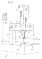
- gantry type CMM 11 shown in gantry design has a measuring table 1, on the columns 2, 3 are movable, which together with a cross member 4 form a portal of the CMM 11.
- the cross member 4 is connected at its opposite ends to the columns 2 and 3, which are mounted longitudinally displaceable on the measuring table 1.
- the cross member 4 is combined with a cross slide 7, which is air-bearing along the cross member 4 (in the X direction) is movable.
- the current position of the cross slide 7 relative to the cross member 4 can be determined by a scale division 6.
- On the cross slide 7 a movable sleeve in the vertical direction 8 is mounted, which is connected at its lower end via a mounting device 10 with a sensor device 5.
- a probe 9 is arranged detachably.
- an additional rotatable measuring table 13 is arranged, on which a measuring object can be arranged, which can be rotated by rotation of the measuring table 13 about a vertical axis of rotation.
- a magazine 14 is arranged on the measuring table 1, in which different probes can be arranged, which can be exchanged for the probe 9, or in the various Tastriche can be arranged, which can be exchanged for the worn by the probe 9 stylus.
- Fig. 1 schematically a controller 12 of the CMM 11, which can be realized for example by a computer which has software and at least one data memory 15 and which is connected via signal and control lines with controllable components of the coordinate measuring machine, in particular with drives.
- the controller 12 is connected via a measurement data connection with those elements of the CMM 11, which are used to determine the coordinate measurements. Since such elements and devices in the field of CMMs are well known, will not be discussed in more detail here.
- Fig. 2 shows a carrier 16 with a sub-carrier 17 attached thereto, which carries a stylus 18 with a measuring ball 19.
- the carrier 16 may, for example, instead of the sensor device 5 on the in Fig. 1 shown coordinate measuring machine 11 are attached.
- the sub-carrier is z. B. a rotary swivel joint, which on the in Fig. 2 lower right end lying a change plate 20, which allows replacement of the attached stylus 18.
- Fig. 5 shows a data structure, for example, in the data memory 15 of the computer or the controller 12 according to Fig. 1 is stored.
- the reference symbols with the lower case letter a at the end, that is to say 11a to 19a, relate to data groups which respectively belong to the component of the coordinate measuring machine 11 (FIG. Fig. 1 and Fig. 2 ) are assigned the same reference number but without the suffix a.
- 11a therefore designates the data group which is assigned to the coordinate measuring machine 11 itself, or the base machine, without the specially additionally arranged components, such as, for example, carrier 16.
- FIG. 12a designates the data group associated with the controller 12.
- Each of the data groups 11a-19a may include, but not necessarily, operating parameters and rules and / or information for determining the operating parameters, with the operating parameters, prescriptions, and information associated with the same data group of the respective component 11-19.
- At least one operating parameter value, a regulation for determining this operating parameter and / or information for determining this operating parameter can be stored in each of the data groups 11a to 19a. Since there are usually a variety of operating parameters, in the procedure described below for determining the operating parameters, the sequence of components can be repeated successively repeatedly for each of the operating parameters. However, the data of several or all operating parameters in the data groups can also be evaluated in one pass of the sequence. In the following, only one will simplify Operating parameters spoken. If a plurality of operating parameters are determined in one run of the sequence, the validity of the same operating parameter as in the previous step is of course checked in a following step or regulations and / or information on the same operating parameter are accepted as valid. However, it is also possible that information or values of another operating parameter are of importance when using such a regulation and are used.
- the method according to the invention in which the sequence of components of a configuration of a coordinate measuring machine is predetermined, can also be referred to as a layer model or layer method.
- the first corresponds to the representation of Fig. 3 lowest layer, the first component in the order. In the case of Fig. 3 this is the component coordinate measuring machine or machine.
- the bottom layer is therefore referred to as "base layer machine parameter" to indicate that the parameters of the machine are first used as the basis for determining the parameter.
- the parameter is the permissible maximum speed along the X axis of a Cartesian coordinate system of the coordinate measuring machine, for example according to the X axis Fig. 1 ,
- this value is accepted as the initially valid value of the operating parameter.
- a value is usually defined in the data group of the machine.
- the component rotary table or turntable 13 In the next higher layer or at the next location in the order of determination is the component rotary table or turntable 13. This is followed by the components magazine 14, carrier or carrier 16, sub-carrier or sub-carrier 17, sensor or Button 19. At the top of the layer structure or in the last position in the sequence of the components is the component control itself or the application software, with the operations on the hitherto valid Value of the operating parameter can be made, for example, to implement specifications of the user.
- An example of a rule for determining an operating parameter is the rule already contained in the lowest layer that the associated operating parameter in the higher layers can be lowered (or increased in the case of another operating parameter), but can not be increased (or increased). in the other case can be lowered).
- the maximum permissible speed of the measuring head may not be increased in higher layers, for example, but only lowered.
- Fig. 4 shows that at least in one of the layers different operating parameters can be considered, which can be classified in the already explained different parameter categories.
- the arrow "Evaluation" left in Fig. 4 does not mean that the parameters within the box should be evaluated in the order from bottom to top. Rather, the arrow refers to the fact that the operating parameters can be considered as part of one and the same layer in the evaluation, which in Fig. 3 is shown schematically.
Landscapes
- Physics & Mathematics (AREA)
- General Physics & Mathematics (AREA)
- Engineering & Computer Science (AREA)
- Automation & Control Theory (AREA)
- Length Measuring Devices With Unspecified Measuring Means (AREA)
- A Measuring Device Byusing Mechanical Method (AREA)
Claims (14)
- Procédé de commande d'un fonctionnement d'un appareil de mesure de coordonnées (11), au moins un paramètre de fonctionnement, tel que la vitesse maximale, l'accélération maximale, la limite d'une zone de déplacement ou la valeur limite d'une reconnaissance de signal, étant déterminé, lequel doit être valable pendant le fonctionnement,
caractérisé par les étapes suivantes :a) à une pluralité de composants (11, 12, 13, 14, 16, 17, 18, 19) de l'appareil de mesure de coordonnées (11) est associée respectivement ou peut être associée respectivement une valeur du paramètre de fonctionnement et/ou une prescription et/ou une information pour la détermination du paramètre de fonctionnement,b) pour la pluralité des composants (11, 12, 13, 14, 16, 17, 18, 19) est prescrit un ordre de détermination du paramètre de fonctionnement,c) lors de la détermination du paramètre de fonctionnement dans l'ordre prescrit de détermination, il est procédé comme suit pour chaque composant (11, 12, 13, 14, 16, 17, 18, 19), étant commencé par le composant (11) qui se trouve en première place dans l'ordre :- si au composant (11, 12, 13, 14, 16, 17, 18, 19) est associée une valeur du paramètre de fonctionnement, celle-ci est reprise comme valeur du paramètre de fonctionnement valable pour le fonctionnement,- si au composant (11, 12, 13, 14, 16, 17, 18, 19) n'est associée aucune valeur du paramètre de fonctionnement, une valeur du paramètre de fonctionnement valable jusqu'à présent reste valable en outre,- si un autre composant (12, 13, 14, 16, 17, 18, 19) est présent dans l'ordre, il est continué par ce composant. - Procédé selon la revendication précédente, lors de la détermination du paramètre de fonctionnement dans l'ordre prescrit selon l'étape c), étant procédé en outre ou en variante comme suit, étant commencé par le composant (11) qui se trouve en première place dans l'ordre :- si au composant est associée une prescription pour la détermination du paramètre de fonctionnement, cette prescription est réalisée et/ou reprise comme prescription valable et/ou,- si au composant (11, 12, 13, 14, 16, 17, 18, 19) est associée une information pour la détermination du paramètre de fonctionnement, l'information est reprise comme information valable,- si un autre composant (12, 13, 14, 16, 17, 18, 19) est présent dans l'ordre, il est continué par ce composant.
- Procédé selon la revendication précédente, à l'étape b) étant enregistré aussi au moins un composant (11, 12, 13, 14, 16, 17, 18, 19) ou un type de composant dans l'ordre qui ne fait pas partie de l'appareil de mesure de coordonnées (11) dans chaque configuration possible de l'appareil de mesure de coordonnées (11), et à l'étape c) étant pris en compte un composant (11, 12, 13, 14, 16, 17, 18, 19) ou un type de composant uniquement si les composants (11, 12, 13, 14, 16, 17, 18, 19) ou au moins un composant du type de composant est présent dans une configuration momentanée de l'appareil de mesure de coordonnées (11).
- Procédé selon l'une quelconque des revendications précédentes, à l'étape a) étant associées des valeurs du paramètre de fonctionnement à au moins l'un des composants (11, 12, 13, 14, 16, 17, 18, 19), la valeur étant fonction d'au moins un autre composant (11, 12, 13, 14, 16, 17, 18, 19) et/ou d'une combinaison de composants (11, 12, 13, 14, 16, 17, 18, 19), et/ou à au moins l'un des composants (11, 12, 13, 14, 16, 17, 18, 19) étant associée une prescription pour la détermination du paramètre de fonctionnement, la prescription étant fonction d'au moins un autre composant (11, 12, 13, 14, 16, 17, 18, 19) et/ou d'une combinaison de composants (11, 12, 13, 14, 16, 17, 18, 19).
- Procédé selon l'une quelconque des revendications précédentes, à l'étape a) étant associée une valeur du paramètre de fonctionnement et/ou une prescription et/ou une information pour la détermination du paramètre de fonctionnement à un type d'un composant (11, 12, 13, 14, 16, 17, 18, 19).
- Procédé selon l'une quelconque des revendications précédentes, une valeur du paramètre de fonctionnement et/ou une prescription et/ou une information pour la détermination du paramètre de fonctionnement étant associée à un exemplaire déterminé d'un composant (11, 12, 13, 14, 16, 17, 18, 19).
- Procédé selon l'une quelconque des revendications précédentes, si une configuration de l'appareil de mesure de coordonnées (11) s'est modifiée, l'étape c) étant réalisée de nouveau pour la configuration modifiée.
- Procédé selon l'une quelconque des revendications précédentes, l'un des composants (11, 12, 13, 14, 16, 17, 18, 19) pour lequel est prescrit l'ordre de détermination, est un programme (12) ou une partie de programme pour la commande du fonctionnement de l'appareil de mesure de coordonnées (11), un utilisateur pouvant faire une prescription pour le programme ou la partie de programme par rapport au paramètre de fonctionnement.
- Commande (12) pour un appareil de mesure de coordonnées (11), en particulier pour la réalisation d'un procédé selon l'une quelconque des revendications précédentes, la commande étant configurée (12) afin de réaliser sa fonction selon au moins un paramètre de fonctionnement de l'appareil de mesure de coordonnées (11), tel que la vitesse maximale, l'accélération maximale, la limite d'une zone de déplacement ou la valeur limite d'une reconnaissance de signal et la commande présentant un dispositif de détermination pour la détermination de l'au moins un paramètre de fonctionnement qui doit être valable pendant le fonctionnement,
caractérisée en ce que la commande est configuréea) afin d'associer à une pluralité de composants (11, 12, 13, 14, 16, 17, 18, 19) de l'appareil de mesure de coordonnées (11) respectivement une valeur du paramètre de fonctionnement et/ou une prescription et/ou une information pour la détermination du paramètre de fonctionnement ou d'utiliser une telle association,b) afin de prescrire pour la pluralité des composants (11, 12, 13, 14, 16, 17, 18, 19) un ordre de détermination du paramètre de fonctionnement ou de procéder selon un ordre prescrit de détermination du paramètre de fonctionnement,c) afin de procéder comme suit lors de la détermination du paramètre de fonctionnement dans l'ordre prescrit de détermination pour chaque composant (11, 12, 13, 14, 16, 17, 18, 19), étant commencé par le composant (12, 13, 14, 16, 17, 18, 19) qui se trouve en première place dans l'ordre :- si au composant (11, 12, 13, 14, 16, 17, 18, 19) est associée une valeur de paramètre de fonctionnement, celle-ci est reprise comme valeur du paramètre de fonctionnement valable pour le fonctionnement,- si au composant (11, 12, 13, 14, 16, 17, 18, 19) n'est associée aucune valeur de paramètre de fonctionnement, une valeur valable jusqu'à présent du paramètre de fonctionnement reste en outre valable,- si un autre composant (12, 13, 14, 16, 17, 18, 19) est présent dans l'ordre, il est continué par ce composant. - Commande selon la revendication précédente, la commande étant configurée de sorte que lors de la détermination du paramètre de fonctionnement dans l'ordre prescrit selon l'étape c), étant procédé en outre ou en variante comme suit, étant commencé par le composant (11) qui se trouve en première place dans l'ordre :- si au composant (11, 12, 13, 14, 16, 17, 18, 19) est associée une prescription pour la détermination du paramètre de fonctionnement, cette prescription est réalisée et/ou reprise comme prescription valable et/ou,- si au composant (11, 12, 13, 14, 16, 17, 18, 19) est associée une information pour la détermination du paramètre de fonctionnement, l'information est reprise comme information valable,- si un autre composant (12, 13, 14, 16, 17, 18, 19) est présent dans l'ordre, il est continué par ce composant.
- Commande selon l'une quelconque des revendications précédentes, la commande (12) présentant un programme (12) ou une partie de programme qui est réalisée pour la détermination de l'au moins un paramètre de fonctionnement et qui est l'un des composants (11, 12, 13, 14, 16, 17, 18, 19), pour lequel l'ordre de détermination est prescrit.
- Commande selon la revendication précédente, la commande (12) étant configurée de telle sorte qu'un utilisateur puisse faire une prescription pour le programme (12) ou pour la partie de programme par rapport au paramètre de fonctionnement.
- Appareil de mesure de coordonnées (11) avec une commande (12) selon l'une quelconque des trois revendications précédentes.
- Programme informatique (12) avec un code de programme pour la réalisation du procédé selon l'une quelconque des revendications précédentes, si le programme informatique s'exécute sur un ordinateur.
Applications Claiming Priority (2)
| Application Number | Priority Date | Filing Date | Title |
|---|---|---|---|
| DE102007004423A DE102007004423A1 (de) | 2007-01-23 | 2007-01-23 | Steuerung eines Betriebes eines Koordinatenmessgerätes |
| PCT/EP2008/000408 WO2008089929A1 (fr) | 2007-01-23 | 2008-01-21 | Commande d'un fonctionnement d'un appareil de mesure de coordonnées |
Publications (2)
| Publication Number | Publication Date |
|---|---|
| EP2115538A1 EP2115538A1 (fr) | 2009-11-11 |
| EP2115538B1 true EP2115538B1 (fr) | 2011-03-02 |
Family
ID=39402742
Family Applications (1)
| Application Number | Title | Priority Date | Filing Date |
|---|---|---|---|
| EP08707141A Active EP2115538B1 (fr) | 2007-01-23 | 2008-01-21 | Commande d'un fonctionnement d'un appareil de mesure de coordonnées |
Country Status (6)
| Country | Link |
|---|---|
| US (1) | US8600523B2 (fr) |
| EP (1) | EP2115538B1 (fr) |
| JP (1) | JP6016321B2 (fr) |
| AT (1) | ATE500541T1 (fr) |
| DE (2) | DE102007004423A1 (fr) |
| WO (1) | WO2008089929A1 (fr) |
Cited By (1)
| Publication number | Priority date | Publication date | Assignee | Title |
|---|---|---|---|---|
| US11047669B2 (en) | 2018-03-05 | 2021-06-29 | Carl Zeiss Industrielle Messtechnik Gmbh | Method and arrangement for increasing a throughput in workpiece measurement |
Families Citing this family (7)
| Publication number | Priority date | Publication date | Assignee | Title |
|---|---|---|---|---|
| JP5179602B2 (ja) * | 2010-02-08 | 2013-04-10 | アンリツ株式会社 | 測定パラメータ入力制御装置及び方法 |
| DE102010015780A1 (de) | 2010-04-20 | 2011-10-20 | Carl Zeiss Industrielle Messtechnik Gmbh | Betrieb einer Koordinatenmessmaschine oder einer Werkzeugmaschine |
| EP2384851B1 (fr) * | 2010-05-03 | 2018-01-03 | Tesa Sa | Système pour mesurer les coordonnées avec adapteur rotatif |
| CH710648A1 (de) | 2015-01-23 | 2016-07-29 | Erowa Ag | Messmaschine zum Vermessen von Werkstücken. |
| US11347368B2 (en) * | 2019-05-07 | 2022-05-31 | Hexagon Metrology, Inc. | Automated inspection process for batch production |
| CN113536656B (zh) * | 2020-04-21 | 2024-08-13 | 卡尔蔡司工业测量技术有限公司 | 用于确定测量测量物体的测量策略的方法和设备及程序 |
| CN112082445B (zh) * | 2020-09-16 | 2021-11-12 | 湖北恒隆汽车系统集团有限公司 | 一种转向螺杆螺旋弹道衰减变化的检测方法及检测装置 |
Family Cites Families (46)
| Publication number | Priority date | Publication date | Assignee | Title |
|---|---|---|---|---|
| US3267434A (en) * | 1961-07-05 | 1966-08-16 | Gen Electric | Information handling system |
| GB1526209A (en) * | 1974-12-23 | 1978-09-27 | Secretary Industry Brit | Automatic stitching machines |
| US4055787A (en) * | 1975-07-28 | 1977-10-25 | Giddings & Lewis, Inc. | Interruptable numerical contouring control system with return to path safeguards |
| US4034354A (en) * | 1975-11-21 | 1977-07-05 | The Bendix Corporation | Programmable interface controller for numerical machine systems |
| JPS5816983B2 (ja) * | 1977-08-26 | 1983-04-04 | 豊田工機株式会社 | 自動芯出装置 |
| DE3206891A1 (de) * | 1982-02-26 | 1983-09-15 | Robert Bosch Gmbh, 7000 Stuttgart | Verfahren zur fehlerdiagnose fuer speicherprogrammierbare steuerungen |
| US4639653A (en) * | 1985-04-15 | 1987-01-27 | Applied Microbotics Corporation | Method and apparatus for performing work in a three dimensional space |
| DE3637410A1 (de) | 1986-11-03 | 1988-05-11 | Zeiss Carl Fa | Verfahren zur messung von drehtischabweichungen |
| CA1299362C (fr) * | 1986-12-10 | 1992-04-28 | Gregory James Mcdonald | Systeme de mesure de coordonnees |
| DE3740070A1 (de) * | 1987-11-26 | 1989-06-08 | Zeiss Carl Fa | Dreh-schwenk-einrichtung fuer tastkoepfe von koordinatenmessgeraeten |
| JPH0715715Y2 (ja) * | 1989-10-19 | 1995-04-12 | 東芝機械株式会社 | 工作機械の位置補正装置 |
| JP3065768B2 (ja) * | 1992-02-07 | 2000-07-17 | 株式会社日立製作所 | 走査型トンネル顕微鏡、走査型原子間力顕微鏡及び類似の測定装置 |
| DE4245012B4 (de) * | 1992-04-14 | 2004-09-23 | Carl Zeiss | Verfahren zur Messung von Formelementen auf einem Koordinatenmeßgerät |
| US5753983A (en) * | 1992-06-16 | 1998-05-19 | 1012384 Ontario, Inc. | Multi-function control switch for electrically operating devices |
| US5453933A (en) * | 1993-09-08 | 1995-09-26 | Hurco Companies, Inc. | CNC control system |
| DE4330873A1 (de) * | 1993-09-13 | 1995-03-16 | Zeiss Carl Fa | Koordinatenmeßgerät mit einem Tastkopf und einer Elektronik zur Verarbeitung des Tastsignals |
| DE69424917T2 (de) * | 1993-11-03 | 2000-10-12 | Bridgestone Corp., Tokio/Tokyo | Verfahren und Vorrichtung zur ablativen Behandlung von elastomerischen Produkten |
| DE4342312A1 (de) * | 1993-12-11 | 1995-06-14 | Zeiss Carl Fa | Verfahren zur Korrektur von schwingungsbedingten Meßfehlern bei Koordinatenmeßgeräten |
| DE19529574A1 (de) * | 1995-08-11 | 1997-02-13 | Zeiss Carl Fa | Koordinatenmeßgerät mit einer Steuerung, die den Tastkopf des Meßgeräts nach Solldaten verfährt |
| FR2745649B1 (fr) * | 1996-03-01 | 1998-04-30 | Bull Sa | Systeme de configuration de logiciels preconfigures sur des systemes ouverts en reseau dans un environnement distribue et procede mis en oeuvre par un tel systeme |
| DE29612861U1 (de) * | 1996-07-24 | 1996-09-12 | Fa. Carl Zeiss, 89518 Heidenheim | Koordinatenmeßgerät mit Meßzeitoptimierung |
| JPH10103948A (ja) * | 1996-09-30 | 1998-04-24 | Tokyo Seimitsu Co Ltd | 表面粗さ形状測定機の測定条件設定方法及びその装置 |
| JPH11156672A (ja) * | 1997-08-25 | 1999-06-15 | Yoshiaki Kakino | 数値制御装置及びこれを備えた工作機械 |
| DE19809690A1 (de) * | 1998-03-06 | 1999-09-09 | Zeiss Carl Fa | Koordinatenmeßgerät mit Benutzerführung |
| EP1028306B1 (fr) | 1998-08-28 | 2008-10-15 | Mitutoyo Corporation | Dispositif et procede d'analyse et de generation d'un programme destine aux mesures de coordonnees et de proprietes de surface d'une piece |
| US6198246B1 (en) * | 1999-08-19 | 2001-03-06 | Siemens Energy & Automation, Inc. | Method and apparatus for tuning control system parameters |
| US6591146B1 (en) * | 1999-09-16 | 2003-07-08 | Hewlett-Packard Development Company L.C. | Method for learning switching linear dynamic system models from data |
| DE10055583B4 (de) * | 1999-12-09 | 2014-06-18 | Heidelberger Druckmaschinen Ag | Verfahren zur Planung und Ablaufsteuerung von Produktionsabläufen |
| GB0004194D0 (en) * | 2000-02-22 | 2000-04-12 | Nat Power Plc | System and method for monitoring a control process in a process plant |
| AU2001247336B2 (en) * | 2000-03-10 | 2006-02-02 | Smiths Detection, Inc. | Control for an industrial process using one or more multidimensional variables |
| US6961625B2 (en) * | 2000-04-04 | 2005-11-01 | Yamaha Hatsudoki Kabushiki Kaisha | Characteristic control device for control subject |
| JP2001350571A (ja) * | 2000-06-08 | 2001-12-21 | Canon Inc | コンピュータによって制御を行う装置の制御装置および制御方法 |
| JP4170567B2 (ja) * | 2000-07-07 | 2008-10-22 | 株式会社ソディック | 工作機械の移動装置および工作機械の移動装置の制御方法 |
| DE10111540A1 (de) * | 2001-03-10 | 2002-09-12 | Zeiss Carl | Koordinatenmeßgerät |
| EP1308810B1 (fr) * | 2001-09-05 | 2005-11-16 | Mikron Comp-Tec AG | Méthode et système d'assistance d'un opérateur lors du réglage des paramètres d'usinage |
| JP2003324055A (ja) * | 2002-04-30 | 2003-11-14 | Canon Inc | 管理システム及び装置及び方法並びに露光装置及びその制御方法 |
| DE10254010B4 (de) * | 2002-11-19 | 2009-01-02 | Siemens Ag | Verfahren zur automatischen Konfiguration einer Parametrieroberfläche von Werkzeugmaschinen oder Produktionsmaschinen |
| KR20050009912A (ko) * | 2003-07-18 | 2005-01-26 | 삼성전자주식회사 | 성능측정 시스템 |
| DE10340363A1 (de) * | 2003-09-02 | 2005-05-25 | Technische Universität Ilmenau | Verfahren zur automatischen optimalen Parametereinstellung von Beleuchtung, Fokus, Bildsensor und Auswerteverfahren optischer Antastsysteme |
| DE102004003941A1 (de) * | 2004-01-26 | 2005-08-11 | Carl Zeiss Industrielle Messtechnik Gmbh | Bestimmung von Koordinaten eines Werkstücks |
| JP4782990B2 (ja) * | 2004-05-31 | 2011-09-28 | 株式会社ミツトヨ | 表面倣い測定装置、表面倣い測定方法、表面倣い測定プログラムおよび記録媒体 |
| DE102004045196A1 (de) * | 2004-09-17 | 2006-03-30 | Siemens Ag | Verfahren zur Anpassung von Parametern einer Steuerungs- oder Regelungseinrichtung |
| DE102005016019B4 (de) * | 2005-04-07 | 2010-12-09 | Carl Zeiss Industrielle Messtechnik Gmbh | Koordinatenmeßsystem mit einem Tastsystem und Verfahren zur Einstellung der Empfindlichkeit des Tastsystems des Koordinatenmeßsystems |
| JP2006308476A (ja) * | 2005-04-28 | 2006-11-09 | Tokyo Seimitsu Co Ltd | 表面粗さ/形状測定装置 |
| DE102005032944A1 (de) * | 2005-07-14 | 2007-01-18 | Robert Bosch Gmbh | Verfahren und Softwaresystem zur Konfiguration eines modularen Systems |
| WO2010078487A2 (fr) * | 2008-12-31 | 2010-07-08 | Pacific Bearing Company | Machine à opérations de fraisage intégrées et simultanées |
-
2007
- 2007-01-23 DE DE102007004423A patent/DE102007004423A1/de not_active Ceased
-
2008
- 2008-01-21 US US12/524,197 patent/US8600523B2/en not_active Expired - Fee Related
- 2008-01-21 JP JP2009546677A patent/JP6016321B2/ja active Active
- 2008-01-21 DE DE502008002730T patent/DE502008002730D1/de active Active
- 2008-01-21 AT AT08707141T patent/ATE500541T1/de active
- 2008-01-21 WO PCT/EP2008/000408 patent/WO2008089929A1/fr not_active Ceased
- 2008-01-21 EP EP08707141A patent/EP2115538B1/fr active Active
Cited By (1)
| Publication number | Priority date | Publication date | Assignee | Title |
|---|---|---|---|---|
| US11047669B2 (en) | 2018-03-05 | 2021-06-29 | Carl Zeiss Industrielle Messtechnik Gmbh | Method and arrangement for increasing a throughput in workpiece measurement |
Also Published As
| Publication number | Publication date |
|---|---|
| EP2115538A1 (fr) | 2009-11-11 |
| US8600523B2 (en) | 2013-12-03 |
| JP2010517020A (ja) | 2010-05-20 |
| DE502008002730D1 (de) | 2011-04-14 |
| DE102007004423A1 (de) | 2008-07-31 |
| ATE500541T1 (de) | 2011-03-15 |
| JP6016321B2 (ja) | 2016-10-26 |
| US20100100199A1 (en) | 2010-04-22 |
| WO2008089929A1 (fr) | 2008-07-31 |
Similar Documents
| Publication | Publication Date | Title |
|---|---|---|
| EP2115538B1 (fr) | Commande d'un fonctionnement d'un appareil de mesure de coordonnées | |
| EP3286524B1 (fr) | Procédé et dispositif permettant de déterminer les propriétés dimensionnelles effectives d'un objet à mesurer | |
| DE3805500C2 (fr) | ||
| DE3627110C2 (fr) | ||
| DE112018006721T5 (de) | Prüfprogrammbearbeitungsumgebung mit automatischen durchsichtigkeitsoperationen für verdeckte werkstückmerkmale | |
| DE102012216908B4 (de) | Verfahren unter Verwendung einer Bildkorrelation zum Bestimmen von Positionsmessungen in einem Maschinenvisionssystem | |
| DE102012220884A1 (de) | Maschinensichtsystemprogramm-Bearbeitungsumgebung mit Echtzeitkontexterzeugungsmerkmalen | |
| EP3274654B1 (fr) | Procédé, dispositif et produit programme d'ordinateur de détermination de propriétés en matière de dimension d'un objet mesuré | |
| DE102012220882A1 (de) | System und Verfahren unter Verwendung eines Bearbeitungsinitialisierungsblocks in einer Teileprogramm-Bearbeitungsumgebung in einem Maschinenvisionssystem | |
| DE102016220127A1 (de) | Verfahren zum Betrieb eines Koordinatenmessgeräts | |
| DE102004019653B4 (de) | Simulationsvorrichtung | |
| EP4089363B1 (fr) | Procédé et dispositif de génération d'un plan d'essai pour l'essai d'un objet de mesure, procédé et dispositif d'essai d'un objet de mesure, ainsi que produit de programme informatique | |
| DE102020211699A1 (de) | Verfahren, Mikroskop und Computerprogramm zum Bestimmen einer Manipulationsposition im probennahen Bereich | |
| DE102016102579A1 (de) | Verfahren und Vorrichtung zum Bestimmen einer Vielzahl von Raumkoordinaten an einem Gegenstand | |
| EP3835900B1 (fr) | Procédé et dispositif d'essai de pièces | |
| EP1078305B1 (fr) | Appareil de mesure de coordonnees et procede pour en assurer la commande | |
| DE102017125677A1 (de) | Verfahren zum Messen eines Werkstückes mit einem Koordinatenmessgerät | |
| EP3875899B1 (fr) | Procédé, produit-programme d'ordinateur et dispositif d'aide à un utilisateur à la création d'un plan de mesure et/ou à la commande d'une mesure à effectuer | |
| DE102015016489A1 (de) | Numerische Steuerung | |
| DE3438007C2 (fr) | ||
| DE102017122627B4 (de) | Optisches Messsystem und Messverfahren | |
| WO1999058931A1 (fr) | Commande d'un appareil de mesure de coordonnees avec une caracteristique de verification et un element geometrique subsequent | |
| EP3889895A1 (fr) | Procédé de recherche des bords d'un objet de mesure | |
| DE10111130A1 (de) | Koordinatenmeßgerät mit einem Videotastkopf | |
| DE102013211914B3 (de) | Verfahren zur Vermessung eines Werkstückes mit einem Koordinatenmessgerät und Koordinatenmessgerät |
Legal Events
| Date | Code | Title | Description |
|---|---|---|---|
| PUAI | Public reference made under article 153(3) epc to a published international application that has entered the european phase |
Free format text: ORIGINAL CODE: 0009012 |
|
| 17P | Request for examination filed |
Effective date: 20090619 |
|
| AK | Designated contracting states |
Kind code of ref document: A1 Designated state(s): AT BE BG CH CY CZ DE DK EE ES FI FR GB GR HR HU IE IS IT LI LT LU LV MC MT NL NO PL PT RO SE SI SK TR |
|
| DAX | Request for extension of the european patent (deleted) | ||
| GRAP | Despatch of communication of intention to grant a patent |
Free format text: ORIGINAL CODE: EPIDOSNIGR1 |
|
| GRAS | Grant fee paid |
Free format text: ORIGINAL CODE: EPIDOSNIGR3 |
|
| GRAA | (expected) grant |
Free format text: ORIGINAL CODE: 0009210 |
|
| AK | Designated contracting states |
Kind code of ref document: B1 Designated state(s): AT BE BG CH CY CZ DE DK EE ES FI FR GB GR HR HU IE IS IT LI LT LU LV MC MT NL NO PL PT RO SE SI SK TR |
|
| REG | Reference to a national code |
Ref country code: GB Ref legal event code: FG4D Free format text: NOT ENGLISH |
|
| REG | Reference to a national code |
Ref country code: CH Ref legal event code: EP |
|
| REG | Reference to a national code |
Ref country code: IE Ref legal event code: FG4D Free format text: LANGUAGE OF EP DOCUMENT: GERMAN |
|
| REF | Corresponds to: |
Ref document number: 502008002730 Country of ref document: DE Date of ref document: 20110414 Kind code of ref document: P |
|
| REG | Reference to a national code |
Ref country code: DE Ref legal event code: R096 Ref document number: 502008002730 Country of ref document: DE Effective date: 20110414 |
|
| REG | Reference to a national code |
Ref country code: NL Ref legal event code: VDEP Effective date: 20110302 |
|
| PG25 | Lapsed in a contracting state [announced via postgrant information from national office to epo] |
Ref country code: NO Free format text: LAPSE BECAUSE OF FAILURE TO SUBMIT A TRANSLATION OF THE DESCRIPTION OR TO PAY THE FEE WITHIN THE PRESCRIBED TIME-LIMIT Effective date: 20110602 Ref country code: GR Free format text: LAPSE BECAUSE OF FAILURE TO SUBMIT A TRANSLATION OF THE DESCRIPTION OR TO PAY THE FEE WITHIN THE PRESCRIBED TIME-LIMIT Effective date: 20110603 Ref country code: LV Free format text: LAPSE BECAUSE OF FAILURE TO SUBMIT A TRANSLATION OF THE DESCRIPTION OR TO PAY THE FEE WITHIN THE PRESCRIBED TIME-LIMIT Effective date: 20110302 Ref country code: ES Free format text: LAPSE BECAUSE OF FAILURE TO SUBMIT A TRANSLATION OF THE DESCRIPTION OR TO PAY THE FEE WITHIN THE PRESCRIBED TIME-LIMIT Effective date: 20110613 Ref country code: LT Free format text: LAPSE BECAUSE OF FAILURE TO SUBMIT A TRANSLATION OF THE DESCRIPTION OR TO PAY THE FEE WITHIN THE PRESCRIBED TIME-LIMIT Effective date: 20110302 Ref country code: SE Free format text: LAPSE BECAUSE OF FAILURE TO SUBMIT A TRANSLATION OF THE DESCRIPTION OR TO PAY THE FEE WITHIN THE PRESCRIBED TIME-LIMIT Effective date: 20110302 Ref country code: HR Free format text: LAPSE BECAUSE OF FAILURE TO SUBMIT A TRANSLATION OF THE DESCRIPTION OR TO PAY THE FEE WITHIN THE PRESCRIBED TIME-LIMIT Effective date: 20110302 |
|
| LTIE | Lt: invalidation of european patent or patent extension |
Effective date: 20110302 |
|
| PG25 | Lapsed in a contracting state [announced via postgrant information from national office to epo] |
Ref country code: SI Free format text: LAPSE BECAUSE OF FAILURE TO SUBMIT A TRANSLATION OF THE DESCRIPTION OR TO PAY THE FEE WITHIN THE PRESCRIBED TIME-LIMIT Effective date: 20110302 Ref country code: NL Free format text: LAPSE BECAUSE OF FAILURE TO SUBMIT A TRANSLATION OF THE DESCRIPTION OR TO PAY THE FEE WITHIN THE PRESCRIBED TIME-LIMIT Effective date: 20110302 Ref country code: BG Free format text: LAPSE BECAUSE OF FAILURE TO SUBMIT A TRANSLATION OF THE DESCRIPTION OR TO PAY THE FEE WITHIN THE PRESCRIBED TIME-LIMIT Effective date: 20110602 Ref country code: FI Free format text: LAPSE BECAUSE OF FAILURE TO SUBMIT A TRANSLATION OF THE DESCRIPTION OR TO PAY THE FEE WITHIN THE PRESCRIBED TIME-LIMIT Effective date: 20110302 Ref country code: CY Free format text: LAPSE BECAUSE OF FAILURE TO SUBMIT A TRANSLATION OF THE DESCRIPTION OR TO PAY THE FEE WITHIN THE PRESCRIBED TIME-LIMIT Effective date: 20110302 |
|
| REG | Reference to a national code |
Ref country code: IE Ref legal event code: FD4D |
|
| PG25 | Lapsed in a contracting state [announced via postgrant information from national office to epo] |
Ref country code: EE Free format text: LAPSE BECAUSE OF FAILURE TO SUBMIT A TRANSLATION OF THE DESCRIPTION OR TO PAY THE FEE WITHIN THE PRESCRIBED TIME-LIMIT Effective date: 20110302 Ref country code: PT Free format text: LAPSE BECAUSE OF FAILURE TO SUBMIT A TRANSLATION OF THE DESCRIPTION OR TO PAY THE FEE WITHIN THE PRESCRIBED TIME-LIMIT Effective date: 20110704 Ref country code: IE Free format text: LAPSE BECAUSE OF FAILURE TO SUBMIT A TRANSLATION OF THE DESCRIPTION OR TO PAY THE FEE WITHIN THE PRESCRIBED TIME-LIMIT Effective date: 20110302 |
|
| PG25 | Lapsed in a contracting state [announced via postgrant information from national office to epo] |
Ref country code: SK Free format text: LAPSE BECAUSE OF FAILURE TO SUBMIT A TRANSLATION OF THE DESCRIPTION OR TO PAY THE FEE WITHIN THE PRESCRIBED TIME-LIMIT Effective date: 20110302 Ref country code: CZ Free format text: LAPSE BECAUSE OF FAILURE TO SUBMIT A TRANSLATION OF THE DESCRIPTION OR TO PAY THE FEE WITHIN THE PRESCRIBED TIME-LIMIT Effective date: 20110302 Ref country code: IS Free format text: LAPSE BECAUSE OF FAILURE TO SUBMIT A TRANSLATION OF THE DESCRIPTION OR TO PAY THE FEE WITHIN THE PRESCRIBED TIME-LIMIT Effective date: 20110702 Ref country code: RO Free format text: LAPSE BECAUSE OF FAILURE TO SUBMIT A TRANSLATION OF THE DESCRIPTION OR TO PAY THE FEE WITHIN THE PRESCRIBED TIME-LIMIT Effective date: 20110302 |
|
| PLBE | No opposition filed within time limit |
Free format text: ORIGINAL CODE: 0009261 |
|
| STAA | Information on the status of an ep patent application or granted ep patent |
Free format text: STATUS: NO OPPOSITION FILED WITHIN TIME LIMIT |
|
| 26N | No opposition filed |
Effective date: 20111205 |
|
| PG25 | Lapsed in a contracting state [announced via postgrant information from national office to epo] |
Ref country code: DK Free format text: LAPSE BECAUSE OF FAILURE TO SUBMIT A TRANSLATION OF THE DESCRIPTION OR TO PAY THE FEE WITHIN THE PRESCRIBED TIME-LIMIT Effective date: 20110302 Ref country code: PL Free format text: LAPSE BECAUSE OF FAILURE TO SUBMIT A TRANSLATION OF THE DESCRIPTION OR TO PAY THE FEE WITHIN THE PRESCRIBED TIME-LIMIT Effective date: 20110302 |
|
| REG | Reference to a national code |
Ref country code: DE Ref legal event code: R097 Ref document number: 502008002730 Country of ref document: DE Effective date: 20111205 |
|
| BERE | Be: lapsed |
Owner name: CARL ZEISS INDUSTRIELLE MESSTECHNIK G.M.B.H. Effective date: 20120131 |
|
| PG25 | Lapsed in a contracting state [announced via postgrant information from national office to epo] |
Ref country code: MC Free format text: LAPSE BECAUSE OF NON-PAYMENT OF DUE FEES Effective date: 20120131 |
|
| REG | Reference to a national code |
Ref country code: CH Ref legal event code: PL |
|
| PG25 | Lapsed in a contracting state [announced via postgrant information from national office to epo] |
Ref country code: LI Free format text: LAPSE BECAUSE OF NON-PAYMENT OF DUE FEES Effective date: 20120131 Ref country code: CH Free format text: LAPSE BECAUSE OF NON-PAYMENT OF DUE FEES Effective date: 20120131 |
|
| PG25 | Lapsed in a contracting state [announced via postgrant information from national office to epo] |
Ref country code: BE Free format text: LAPSE BECAUSE OF NON-PAYMENT OF DUE FEES Effective date: 20120131 |
|
| PGFP | Annual fee paid to national office [announced via postgrant information from national office to epo] |
Ref country code: FR Payment date: 20130213 Year of fee payment: 6 |
|
| PG25 | Lapsed in a contracting state [announced via postgrant information from national office to epo] |
Ref country code: MT Free format text: LAPSE BECAUSE OF FAILURE TO SUBMIT A TRANSLATION OF THE DESCRIPTION OR TO PAY THE FEE WITHIN THE PRESCRIBED TIME-LIMIT Effective date: 20110302 |
|
| REG | Reference to a national code |
Ref country code: AT Ref legal event code: MM01 Ref document number: 500541 Country of ref document: AT Kind code of ref document: T Effective date: 20130121 |
|
| PG25 | Lapsed in a contracting state [announced via postgrant information from national office to epo] |
Ref country code: TR Free format text: LAPSE BECAUSE OF FAILURE TO SUBMIT A TRANSLATION OF THE DESCRIPTION OR TO PAY THE FEE WITHIN THE PRESCRIBED TIME-LIMIT Effective date: 20110302 |
|
| PG25 | Lapsed in a contracting state [announced via postgrant information from national office to epo] |
Ref country code: LU Free format text: LAPSE BECAUSE OF NON-PAYMENT OF DUE FEES Effective date: 20120121 Ref country code: AT Free format text: LAPSE BECAUSE OF NON-PAYMENT OF DUE FEES Effective date: 20130121 |
|
| PG25 | Lapsed in a contracting state [announced via postgrant information from national office to epo] |
Ref country code: HU Free format text: LAPSE BECAUSE OF FAILURE TO SUBMIT A TRANSLATION OF THE DESCRIPTION OR TO PAY THE FEE WITHIN THE PRESCRIBED TIME-LIMIT Effective date: 20080121 |
|
| REG | Reference to a national code |
Ref country code: FR Ref legal event code: ST Effective date: 20140930 |
|
| PG25 | Lapsed in a contracting state [announced via postgrant information from national office to epo] |
Ref country code: FR Free format text: LAPSE BECAUSE OF NON-PAYMENT OF DUE FEES Effective date: 20140131 |
|
| P01 | Opt-out of the competence of the unified patent court (upc) registered |
Effective date: 20230525 |
|
| PGFP | Annual fee paid to national office [announced via postgrant information from national office to epo] |
Ref country code: GB Payment date: 20260123 Year of fee payment: 19 |
|
| PGFP | Annual fee paid to national office [announced via postgrant information from national office to epo] |
Ref country code: DE Payment date: 20260121 Year of fee payment: 19 |
|
| PGFP | Annual fee paid to national office [announced via postgrant information from national office to epo] |
Ref country code: IT Payment date: 20260126 Year of fee payment: 19 |