EP2116120B1 - Méthode de commande d'une combinaison tracteur-outil agricole comprenant au moins un équipement échangeable - Google Patents
Méthode de commande d'une combinaison tracteur-outil agricole comprenant au moins un équipement échangeable Download PDFInfo
- Publication number
- EP2116120B1 EP2116120B1 EP09005439.6A EP09005439A EP2116120B1 EP 2116120 B1 EP2116120 B1 EP 2116120B1 EP 09005439 A EP09005439 A EP 09005439A EP 2116120 B1 EP2116120 B1 EP 2116120B1
- Authority
- EP
- European Patent Office
- Prior art keywords
- control
- tractor
- working
- operating
- way
- Prior art date
- Legal status (The legal status is an assumption and is not a legal conclusion. Google has not performed a legal analysis and makes no representation as to the accuracy of the status listed.)
- Active
Links
Images


Classifications
-
- A—HUMAN NECESSITIES
- A01—AGRICULTURE; FORESTRY; ANIMAL HUSBANDRY; HUNTING; TRAPPING; FISHING
- A01B—SOIL WORKING IN AGRICULTURE OR FORESTRY; PARTS, DETAILS, OR ACCESSORIES OF AGRICULTURAL MACHINES OR IMPLEMENTS, IN GENERAL
- A01B63/00—Lifting or adjusting devices or arrangements for agricultural machines or implements
Definitions
- the invention relates to a method for operating a controller for a tractor unit combination in agriculture according to the preamble of the independent claim 1.
- Cultivated, towed or semi-mounted agricultural machines for attachment to agricultural tractors are generally working machines, which are referred to as interchangeable equipment in accordance with the EC Machinery Directive. This means that these interchangeable equipment do not have their own drive system and therefore only become a usable and therefore complete machine in combination with a tractor.
- the driver of these machines is thus in a control-technical interaction, on the one hand with the tractor as a mobile machine and the power source combustion engine as a drive unit and on the other hand with the interchangeable equipment that has picked up its tractor, and continue with the environment in which this unit moves and is deployed.
- the human being as a driver is thus part of the mobile unit "man-machine” and, at the same time, control-technically part of the cybernetic system "tractor-interchangeable equipment", which he masters safely and safely when used properly and for himself to use his environment.
- the tractor as the universal drive machine in agriculture, has interfaces as an adapter for receiving and controlling the interchangeable equipment.
- connection points such as three-point power lift or PTO for power transmission, fluidic connectors, such as hydraulic pneumatic taps or electrical connectors, but also connection points such as ISO bus connector for transmitting control signals, actuation of actuators or Returning information content for obtaining information for displaying it on suitable display devices, such as displays.
- This also includes the coupling of job computers with control and display devices and their coupling with the tractor's own control and display devices, such as displays with multifunction buttons to trigger control signals for the tractor itself or for job computer part of the "tractor-interchangeable equipment".
- the classic adjusting devices such as manually operated or electrically actuatable directional control valves on the control console placed laterally from the driver's seat, are also available as hydraulic control devices of control devices on board the tractor. These control signals can also be actuated, for example, by the control lever - also known as the joy stick.
- the choice of the type of actuation and the activatable controls themselves is left to the driver in modern tractors, who can choose between different options.
- the EP 1 044 591 A discloses such a head-land management asnosmanaqementsystem whose control unit comprises means for executing a learning mode, in particular for the so-called headland.
- the DE 199 43 561 discloses a tractor that describes the technical requirements of a head-land management in connection with the application of the classical agricultural bus system (LBS) in conjunction with a job computer of the tractor and optionally in conjunction with a device-side job computer.
- LBS classical agricultural bus system
- the primary goal is to give the driver a control that relieves him cognitively in terms of the applied concentration on control tasks. At the same time, this should also make a contribution to increasing occupational safety in dealing with these machine combinations.
- the tractor unit combination comprises two control modes such that with the one control mode at least one drive unit or one or more actuators either manually via a control terminal and its control keys software supported by the device side job computer, or alternatively with the second control mode manually via the control valves or whose valve disks of the control valve block of the working hydraulics of the tractor can be actuated, wherein both control modes are concatenated and connected in parallel active.
- the invention provides to combine the advantages of manual hand control of a tractor hydraulics with the advantages of a complexity-oriented microprocessor control of one or more job computers of interchangeable equipment such that it is possible to associate a preselectable microprocessor-controlled control mode with a manually operated hand control operator of the tractor hydraulics in that this control mode is assigned to this operating element in self-holding and thus the complex control process can be triggered by the actuation of this operating element.
- the assignment of this control mode in latching with respect to the control of the tractor hydraulic system is maintained until another control command is triggered by actuation of a control element of the control terminal of the microprocessor control, which thus also terminates the latching of the assignment of the control mode.
- control commands which are triggered by controls of the control terminal of the microprocessor control, priority over the control commands, triggerable in self-holding control mode of the control element of the manual control of the tractor hydraulics.
- This change of control modes is particularly advantageous when it is interchangeable equipment with large working widths, as is the case for example with large harvesters such as mowers or rakes, and the multi-part folding work units that can be operated by separate actuators, and that they have to be excavated at the headland and returned to their working position after maneuvering in the headlands, so that the driver has to carry out constantly recurring and identical control sequences.
- the inventive and associated ergonomic advantage for the driver is that he does not constantly reorient his line of sight at the end of the field again on the control terminal and must focus on the selection and operation of the corresponding control buttons, so that his arm supported on the control panel can lie and thus he can maintain contact with the control of the tractor hydraulics.
- the choice of the right control of the tractor hydraulics comes to him ergonomically alone by the fact that his trained and trained sense of touch him very helpful comes along, since it is in this type of operation in his daily working environment virtually recurring device-independent Repetitions of operations and which greatly enhances the operator safety.
- the invention is by no means limited to the control of the lifting or lowering operations at the field end, but also to control operations during operation between the Vorgeick, such as the mowing of remnants of field edges that can not be done with all available mowing units because otherwise already mown green fodder is again caught by the mowing units and unnecessarily crushed and whirled up. Again, it is important to create an ergonomically improved situation to the effect that the driver finds with the least control effort in the most comfortable and safest control mode back.
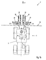
- Fig.1 shows a combination shown simplistic ⁇ as a working machine 53 formed of a tractor 1 and a replaceable equipment 2 with three working units 26,27,28 using the example of a three-piece mower in a plan view of the working plane, wherein Fig.1 a the hydraulic actuators for actuating the working units are shown with. 1b shows shows according to Fig.1 a the hydraulic actuators designed as hydraulic cylinders 20,21,22,22 ', 23,24,25,25') considered to operate the working units 26,27,28 isolated, wherein for reasons of clarity, the working units are not shown.
- Each of the working units 26,27,28 can be lifted or folded from the ground out of the working position in a conventional manner either in a headland position or in a transport position for road transport.
- the headland position is an intermediate position between the clean working position, in which all work units are supported on the ground and a raised intermediate position, and the transport position.
- the headland position is used to disengage the work tools from their assigned work task to turn the tractor at the field end and to maneuver it in the new direction of travel.
- the two outer work units left and right 26,27 are guided on their cantilever arms 29,30, wherein the Cantilever arms 29,30 of hydraulic cylinders 20,21 are pivotable about pivot axes 46,47 and thus can be lifted into their headland, or transport position from the ground.
- the average working unit 28 can now be lifted from a headland and transport position now by the hydraulic cylinders 22,22 'and pivotable about pivot axes 48,49 from the ground.
- the outer work units left and right 26,27 are additionally weight relieved of prestressed hydraulic cylinders 23,24 and the average working unit 28 of prestressed hydraulic cylinders 25,25 'and thus take over a soil pressure relief to protect the remaining green feed stock on the ground.
- the interchangeable equipment 2 is received by the three-point linkage 5 as an interface 19 between the tractor 1 and the interchangeable equipment 2.
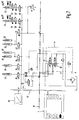
- Fig.2 shows in a symbolized representation of the system tractor 1 / multi-part interchangeable equipment 2 as a total machine 53 in its normal position, ie none of the controls of the control tractor 1 / multi-part interchangeable equipment 2 is activated and all controls and controls are in the non-actuated state.
- the tractor 1 as a mobile drive and energy source for receiving the interchangeable equipment 2 includes the driver's cab 3 as a control station of the driver, in accordance with the EN ISO 12100 also simultaneously the user of the machine - in this specific case the combination tractor 2 / interchangeable equipment 1 - and that it must be protected, in particular, from risks that may arise from potential sources of danger,
- the driver is located during operation and the transport journey within the cab 3 on his driver's seat 45.
- the cab 3 is also the control station overall tractor / interchangeable equipment and on this are therefore also the controls of the two control systems 4,15, namely the controls Valve disks 31,32 of the control block 4 of the working hydraulics and the operating terminal 7 with its function keys 9,10,11,12,13,14,15 the job computer control 15th
- the block of manual control valves 4 of the working hydraulics for the interchangeable equipment 2 and on the other hand, the control terminal 7 with its function keys 9,10,11,12,13,14,15 and its optical display 17 running as Display, as shown enlarged in Fig. 2a, wherein both controls 4,15 which concerns the actuators and the actuators of the interchangeable equipment, access the working hydraulics with the hydraulic pump 6 of the tractor 1 back.
- the tractor 1 On board the tractor 1 is also the hydraulic pump 6 to the pressure oil supply to the working hydraulics, via the pressure line P, the tank return line T, and the valve discs 31,32 of the manual control valve block 4 and the taps P1, P2, T at the interface 19 with the electromagnetic actuated directional valves 33,34,34 ', 35,35', 36,36 '37,37 ', which are part of the interchangeable equipment 2 and the control of the hydraulic cylinders 20,21,22,22', 23,24,25 Serve, is connected.
- the interchangeable equipment 2 comprises at least one device-side job computer 18, which via a field bus 17, preferably an ISO bus, with the operating terminal 7 and the electrically operated directional valves 33,34,34 ', 35,35', 36, 36'37,37 'is connected. It is advantageous, in particular for reasons of safety, to equip the interchangeable equipment 2 with at least two job computers 18, 18 ', which check each other for functional reliability and which can additionally be configured redundantly to each other, which determines the functional reliability and thus the diagnostic coverage increased in case of failure of any of the electronic component.
- the control according to the invention is designed so that it is designed as a duo-mode control.
- the tractor unit combination 50 comprises at least two control modes such that with this control on the one hand at least one drive unit or actuators 20, 22, 22 ', 23, 24, 25, 25' either via the operating terminal 7 and its operating keys 8, 9, 10,11,12,13,14,15 software supported by the device-side job computer 18,18 'or alternatively manually via the control valves in manual mode via the valve disks 31,32 of the control valve block 4 of the working hydraulics of the tractor is actuated, both control modes are active in parallel.
- valve discs 31,32 itself also be electrically actuated, and this can be controlled depending on the equipment level of a tractor, for example, by a joy stick.
- the decisive factor for the working hydraulic control valve block control mode is that the driver can access the controls of the tractor in order to trigger the essential control commands during the working run and the driver's steering hand can always remain near these controls without his having to pay attention must direct the operating buttons of the operator terminal.
- the control is configured in the control mode working hydraulic valve block such that at least one device-side job computer 18, 18 'is included in the process and monitoring of the manually triggered control commands via at least one of the valve disks 31, 32.
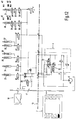
- Figure 3 shows the control system in the initial situation in transport position, ie in the position that results when the field is reached after driving on public roads.
- the external work units are folded up in the transport position, so that the upper position sensors 42,42 'detect this starting position and the job computer 18 report this condition.
- the valve disc 31 is brought into switching position as in Fig. 4 so that the entire system of the controller can be supplied with pressure oil.
- the valve disc 31 remains in latching locked so that so that the mode working position is established, as long as the valve disc 31 remains in this Verasteten position.
- the working position achieved is detected by the position sensors 44, 44 ', which report their condition to the job computer 18 as a high signal and input signals.
- this input signal is applied to the job computer in latching and stored until the end of the division of labor is brought about by the control key 14, and which causes the working units from the working position back to the transport position.
- the respective state of the working units can be communicated via visual display 16 (display) additionally visualized to the driver.
- both control systems 4,15 on the one hand designed as a control block 4 with at least two valve discs C, and on the other hand designed as job computer control 15, based on the microprocessor-controlled job computer 18,18 ', networked miteinender control technology and are connected in parallel active.
- both control systems 4,15 takes place on the one hand via the valve disks 18,18 'of the working hydraulics and on the other hand via the electrically controllable directional valves 33,34,34', 35,35 ', 36,36 '37,37' and the position sensors 42,42 ', 43,43', 44 and the pressure sensor 41, which give the job computer 18,18 'information about the current state of the interchangeable equipment 2.
- Both control systems are always active in the working mode independently active and independently operable.
- FIG 5 is the switching position of the controller in the working position from which the lifting of the working units is to be started in the headland position shown.
- This lifting can alternatively be performed either by pressing the corresponding control button 13 on the control terminal 7 or by operating the valve disc 32.
- the valve disc 32 is actuated, which is illustrated by the changed valve position.
- the blackened areas on the valves and position sensors mean that they are in the excited state. All other directional valves are also blackened according to their non-energized valve positions and shown in their respective energized position.
- the pressure sensor 41 which can distinguish between a low pressure p and a high pressure p +. It can be a simple pressure switch or a single pressure switch Bus-capable sensor that can create its print state to the input of the job computer.
- FIG. 6 shows the switching position of the control in the headland position reached and Figure 7 shows the switching position of the controller out of the position of the headland position to lower the work units back to the working position.
- Fig. 8 shows the switch position of the control again returned in the position all work units in working position on the ground.
- Figure 9 shows the switching position of the control start of Einzelaushubs the right-hand unit 27 for transfer to the headland position, which is triggered by a pressure of the control button 10 on the control terminal 7. After reaching the headland position or the position sensor 43 'of the excavation is stopped automatically.
- Figure 10 shows the switching position of the controller in the Situation Single excavation of the right working unit in the raised headland position. Such an operation may be required, for example, to override an obstacle.
- Figure 11 shows the switching position of the control start of the remaining work units 26,28 in the headland position, with the right unit 27 already in the headland position, as under Figure 9 and Figure 10 described is located.
- the triggering of this control command is actuated by the valve disk 32 of the control block 4 of the working hydraulics.
- the control button 13 of the control terminal 7 could be actuated, which can trigger the same control process.
- Figure 12 shows this switching position of the controller in the situation all mowers are located in the headland position.
- the working units can be lowered back into the working position either either by actuation of the valve disk 32 in the corresponding position, or even alternatively by actuation of the operating key 11 of the operating terminal 7.
- control is also a method of controlling the overall machine tractor / interchangeable equipment.
Landscapes
- Life Sciences & Earth Sciences (AREA)
- Engineering & Computer Science (AREA)
- Mechanical Engineering (AREA)
- Soil Sciences (AREA)
- Environmental Sciences (AREA)
- Lifting Devices For Agricultural Implements (AREA)
- Control By Computers (AREA)
Claims (12)
- Procédé d'actionnement d'un moyen de commande pour un ensemble tracteur-outil (1, 2) comprenant au moins un équipement échangeable (2), lesquels forment par leur action conjointe une machine de travail agricole, le tracteur (1) comportant un circuit hydraulique de fonctionnement avec au moins un moyen de commande conformé en bloc de commande (4) avec au moins deux valves directionnelles, de préférence deux segments de bloc de valves (31, 32), l'équipement échangeable (2) pouvant être couplé par l'intermédiaire d'au moins une prise de force hydraulique au circuit hydraulique de fonctionnement du tracteur (1), et l'équipement échangeable (2) comportant un moyen de commande (15) en forme de calculateur de tâches commandé par microprocesseur (18, 18'), lequel est relié à une unité d'actionnement (7) de manière télécommandée depuis la cabine de conduite (3) du tracteur (1), les instructions de commande destinées à commander l'équipement échangeable (2) pouvant être émises soit par l'unité d'actionnement (7) soit par le bloc de commande (4) et agissant sur des actionneurs et/ou des unités d'entraînement et/ou des mécanismes de positionnement de l'équipement échangeable (2), caractérisé en ce que l'ensemble tracteur-outil (50) comporte un moyen de commande à deux modes (51) comprenant deux modes de commande, de façon qu'au moins une unité d'entraînement ou un ou plusieurs mécanismes de positionnement soient actionnables dans l'un des modes de commande manuellement par l'intermédiaire d'un terminal d'actionnement (7) et de ses touches d'actionnement (9, 10, 11, 12, 13) sous assistance logicielle par l'intermédiaire du calculateur de tâches côté outil (18, 18') ou, selon une variante, dans le second mode de commande manuellement par l'intermédiaire des valves de commande, respectivement de leurs segments de bloc de valves (31, 32) du bloc de valves de commande (4) du circuit hydraulique de fonctionnement du tracteur (1), les deux modes de commande étant enchaînés et montés activement en parallèle, le moyen de commande manuelle d'un circuit hydraulique de tracteur étant combiné avec le moyen de commande à microprocesseur orienté complexité d'un ou de plusieurs calculateurs de tâches (18, 18') d'un équipement échangeable, de sorte qu'il est possible d'assigner un mode de commande présélectionnable, commandé par microprocesseur, à un élément d'actionnement à action manuelle du moyen de commande manuel du circuit hydraulique de tracteur, de façon que ce mode de commande soit assigné à cet élément d'actionnement en auto-maintien, l'actionnement de cet élément d'actionnement permettant de déclencher l'opération de commande complexe, l'assignation de ce mode de commande en auto-maintien par rapport à l'unité d'actionnement du circuit hydraulique de tracteur restant maintenue jusqu'à ce que soit déclenchée, par actionnement d'un élément d'actionnement du terminal d'actionnement (7) du moyen de commande à microprocesseur, une autre instruction de commande qui met simultanément fin à l'auto-maintien de l'assignation du mode de commande.
- Procédé selon la revendication 1, caractérisé en ce que les deux systèmes de commande (4, 15), celui du circuit hydraulique de fonctionnement, conformé en bloc de commande (4) avec au moins deux segments de bloc de valves (31, 32), et celui du moyen de commande à calculateur de tâches (15) avec au moins un calculateur de tâches côté outil (18, 18'), sont actionnables parallèlement l'un à l'autre, les deux systèmes de commande (4, 15) étant mis en réseau entre eux et montés activement en parallèle l'un à l'autre.
- Procédé selon la revendication 1, caractérisé en ce que la mise en réseau de deux systèmes de commande (4, 15) s'effectue, d'une part, par l'intermédiaire des segments de bloc de valves (31, 32) du circuit hydraulique de fonctionnement du tracteur (1) et, d'autre part, par l'intermédiaire de valves directionnelles commandées électriquement (34, 34', 35, 35', 37, 37 ; 38, 39, 40), d'au moins un capteur de position (42, 42', 43, 43', 44) et d'au moins un capteur de pression (41).
- Procédé selon la revendication 1, caractérisé en ce que le montage en parallèle des deux systèmes de commande (4, 15) s'effectue, d'une part, par l'intermédiaire des segments de bloc de valves (31, 32) du circuit hydraulique de fonctionnement du tracteur (1) et, d'autre part, par l'intermédiaire de valves directionnelles commandées électriquement (34, 34', 35, 35', 37, 37 ; 38, 39, 40), d'au moins un capteur de position (42, 42', 43, 43', 44) et d'au moins un capteur de pression (41).
- Procédé selon la revendication 1, caractérisé en ce qu'en mode de travail les deux systèmes de commande (4, 15) sont toujours montés activement indépendamment l'un de l'autre.
- Procédé selon la revendication 1, caractérisé en ce que le moyen de commande comprend un terminal d'actionnement (7).
- Procédé selon la revendication 1, caractérisé en ce que le terminal d'actionnement (7) fait partie de l'équipement échangeable (2).
- Procédé selon la revendication 1, caractérisé en ce que le terminal d'actionnement (7) fait partie de l'équipement du tracteur (1).
- Procédé selon la revendication 1, caractérisé en ce que le moyen de commande comprend un bus de champ (17).
- Procédé selon la revendication 1, caractérisé en ce que le moyen de commande (4, 15) comprend au moins un capteur de pression (41) qui génère au moins un signal d'entrée pour le calculateur de tâches (18, 18').
- Procédé selon la revendication 1, caractérisé en ce que le moyen de commande (4, 15) comprend au moins un capteur de position (42, 42', 43, 43', 44) qui génère au moins un signal d'entrée pour le calculateur de tâches (18, 18').
- Procédé selon la revendication 1, caractérisé en ce que l'équipement échangeable (2) comprend un mécanisme de coupe avec au moins deux unités de travail (26, 27).
Priority Applications (1)
| Application Number | Priority Date | Filing Date | Title |
|---|---|---|---|
| SI200931481A SI2116120T1 (sl) | 2008-05-09 | 2009-04-16 | Postopek za delovanje krmilja za kombinacijo traktorja in traktorskega priključka z vsaj enim zamenljivim traktorskim priključkom |
Applications Claiming Priority (1)
| Application Number | Priority Date | Filing Date | Title |
|---|---|---|---|
| DE200810023068 DE102008023068A1 (de) | 2008-05-09 | 2008-05-09 | Steuerung für angebaute, gezogene oder aufgesattelte Landmaschinen, als ausechselbare Ausrüstung in Verbindung mit Traktoren |
Publications (2)
| Publication Number | Publication Date |
|---|---|
| EP2116120A1 EP2116120A1 (fr) | 2009-11-11 |
| EP2116120B1 true EP2116120B1 (fr) | 2016-05-11 |
Family
ID=39942487
Family Applications (1)
| Application Number | Title | Priority Date | Filing Date |
|---|---|---|---|
| EP09005439.6A Active EP2116120B1 (fr) | 2008-05-09 | 2009-04-16 | Méthode de commande d'une combinaison tracteur-outil agricole comprenant au moins un équipement échangeable |
Country Status (3)
| Country | Link |
|---|---|
| EP (1) | EP2116120B1 (fr) |
| DE (2) | DE102008023068A1 (fr) |
| SI (1) | SI2116120T1 (fr) |
Cited By (1)
| Publication number | Priority date | Publication date | Assignee | Title |
|---|---|---|---|---|
| DE102018124705A1 (de) * | 2018-10-08 | 2020-04-09 | Lemken Gmbh & Co. Kg | Nachrüstkit zum Anbau an ein landwirtschaftliches Gerät |
Families Citing this family (8)
| Publication number | Priority date | Publication date | Assignee | Title |
|---|---|---|---|---|
| DE102010032125B4 (de) * | 2010-07-24 | 2017-05-04 | Hilde Schlögl | Steuerungskasten sowie Steuervorrichtung für Nutzfahrzeuge |
| FR2965454B1 (fr) | 2010-10-05 | 2012-09-07 | Exel Ind | Engin agricole de pulverisation et procede de pulverisation d'un liquide phytosanitaire sur un terrain cultive au moyen d'un tel engin |
| DE102010048819A1 (de) | 2010-10-20 | 2012-04-26 | Roland Lipp | Hochgeschwindigkeits-Fernverkehrssystem zum Transport von Personen und/oder Lasten |
| CN103109611A (zh) * | 2011-11-17 | 2013-05-22 | 常州联发凯迪机械有限公司 | 拖拉机分配器操纵机构 |
| FR3005912B1 (fr) * | 2013-05-24 | 2016-12-02 | Etablissements Emily | Boitier de commande a double pupitre |
| WO2015113752A1 (fr) | 2014-01-31 | 2015-08-06 | AgBRAIN - AGRITECHNICAL BASIC RESEARCH FOR ADVANCED INNOVATION GMBH | Terminal de commande d'une machine agricole équipé d'un logiciel hyperviseur |
| SE540462C2 (sv) * | 2015-06-18 | 2018-09-18 | Vaederstad Holding Ab | Lantbruksredskap samt förfarande för matning av hydraulisk kraft till ett lantbruksredskap |
| SI25059A (sl) * | 2015-09-11 | 2017-03-31 | Univerza V Mariboru | Metoda in naprava za izrabo nizkotemperaturnih virov plinskih kotlov z visokotemperaturno toplotno črpalko po konceptu voda/voda |
Family Cites Families (3)
| Publication number | Priority date | Publication date | Assignee | Title |
|---|---|---|---|---|
| US6292729B2 (en) * | 1999-04-14 | 2001-09-18 | Deere & Company | Vehicle function management system |
| DE19943561B4 (de) | 1999-09-13 | 2017-04-06 | Gebr. Pöttinger GmbH | Landwirtschaftlicher Schlepper für unterschiedlich angehängte oder angebaute Geräte |
| EP1666996B1 (fr) * | 2002-02-26 | 2013-08-14 | CLAAS Selbstfahrende Erntemaschinen GmbH | Procédé destiné à la commande de machines agricoles |
-
2008
- 2008-05-09 DE DE200810023068 patent/DE102008023068A1/de not_active Withdrawn
- 2008-05-09 DE DE202008007912U patent/DE202008007912U1/de not_active Expired - Lifetime
-
2009
- 2009-04-16 SI SI200931481A patent/SI2116120T1/sl unknown
- 2009-04-16 EP EP09005439.6A patent/EP2116120B1/fr active Active
Cited By (1)
| Publication number | Priority date | Publication date | Assignee | Title |
|---|---|---|---|---|
| DE102018124705A1 (de) * | 2018-10-08 | 2020-04-09 | Lemken Gmbh & Co. Kg | Nachrüstkit zum Anbau an ein landwirtschaftliches Gerät |
Also Published As
| Publication number | Publication date |
|---|---|
| DE202008007912U1 (de) | 2008-11-06 |
| DE102008023068A1 (de) | 2009-11-12 |
| EP2116120A1 (fr) | 2009-11-11 |
| SI2116120T1 (sl) | 2016-09-30 |
Similar Documents
| Publication | Publication Date | Title |
|---|---|---|
| EP2116120B1 (fr) | Méthode de commande d'une combinaison tracteur-outil agricole comprenant au moins un équipement échangeable | |
| EP0590692B1 (fr) | Système de commande pour le réglage de position de dispositifs d'attelage | |
| EP3245856B1 (fr) | Système de contrôle d'une interface d'appareil d'un engin agricole | |
| EP2014504B1 (fr) | Dispositif de commande destiné à la commande d'au moins une taille d'état d'un véhicule utilitaire agricole ou industriel | |
| EP1988222B1 (fr) | Dispositif de commande | |
| EP1044591A2 (fr) | Système de gestion de la fonction pour vehicules | |
| EP1270306B1 (fr) | Commande de démarrage et d'arrêt d'une prise de force d'un véhicule agricole | |
| DE102005058672A1 (de) | Konfigurierbares Hydrauliksystem für einen landwirtschaftlichen Traktor und eine Arbeitsgerätekombination | |
| DE102010047068A1 (de) | Heuwerbungsmaschine zum Wenden vom am Boden liegenden Erntegut | |
| EP0820688B1 (fr) | Dispositif pour le contrôle au minimum d'un actionneur d'un véhicule utilitaire | |
| EP3616488B1 (fr) | Dispositif de commande adaptatif et procédé d'adaptation d'un dispositif de commande | |
| DE102010008487A1 (de) | Zugmaschine mit externer Steuerung | |
| DE102019208346A1 (de) | Landwirtschaftlicher Traktor mit einem an diesen ankuppelbaren Anbaugerät sowie Verfahren zum Betrieb eines landwirtschaftlichen Traktors mit einem an diesen ankuppelbaren Anbaugerät | |
| DE102018114882A1 (de) | Selbstfahrendes Rasenpflegegeräte-Trägerfahrzeug | |
| EP3798104A1 (fr) | Véhicule agricole | |
| EP1622443B1 (fr) | Dispositif et procede de commande du systeme de levage d'un vehicule agricole | |
| DE102015224747A1 (de) | Feldrandbereich-betriebssteuerungssystem | |
| DE102006045270B3 (de) | Mähmaschine | |
| EP4438444B1 (fr) | Procédé de fonctionnement d'une direction hydrostatique de véhicule | |
| EP4272524B1 (fr) | Combinaison de véhicule agricole | |
| EP3769600B1 (fr) | Engin de travail agricole | |
| EP4092200A1 (fr) | Engin de travail agricole | |
| EP1239208A2 (fr) | Circuit électro-hydraulique pour laisser échapper la pression dans les raccords rapides | |
| DE102022100543A1 (de) | Fernsteuerbare selbstfahrende Rasenpflegevorrichtung | |
| EP4032787A1 (fr) | Machine de travail agricole, ainsi que dispositif de commande |
Legal Events
| Date | Code | Title | Description |
|---|---|---|---|
| PUAI | Public reference made under article 153(3) epc to a published international application that has entered the european phase |
Free format text: ORIGINAL CODE: 0009012 |
|
| AK | Designated contracting states |
Kind code of ref document: A1 Designated state(s): AT BE BG CH CY CZ DE DK EE ES FI FR GB GR HR HU IE IS IT LI LT LU LV MC MK MT NL NO PL PT RO SE SI SK TR |
|
| 17P | Request for examination filed |
Effective date: 20100511 |
|
| 17Q | First examination report despatched |
Effective date: 20100624 |
|
| GRAP | Despatch of communication of intention to grant a patent |
Free format text: ORIGINAL CODE: EPIDOSNIGR1 |
|
| INTG | Intention to grant announced |
Effective date: 20151222 |
|
| GRAS | Grant fee paid |
Free format text: ORIGINAL CODE: EPIDOSNIGR3 |
|
| GRAA | (expected) grant |
Free format text: ORIGINAL CODE: 0009210 |
|
| AK | Designated contracting states |
Kind code of ref document: B1 Designated state(s): AT BE BG CH CY CZ DE DK EE ES FI FR GB GR HR HU IE IS IT LI LT LU LV MC MK MT NL NO PL PT RO SE SI SK TR |
|
| REG | Reference to a national code |
Ref country code: GB Ref legal event code: FG4D Free format text: NOT ENGLISH |
|
| REG | Reference to a national code |
Ref country code: CH Ref legal event code: EP |
|
| REG | Reference to a national code |
Ref country code: AT Ref legal event code: REF Ref document number: 797872 Country of ref document: AT Kind code of ref document: T Effective date: 20160515 |
|
| REG | Reference to a national code |
Ref country code: IE Ref legal event code: FG4D Free format text: LANGUAGE OF EP DOCUMENT: GERMAN |
|
| REG | Reference to a national code |
Ref country code: DE Ref legal event code: R096 Ref document number: 502009012551 Country of ref document: DE |
|
| REG | Reference to a national code |
Ref country code: NL Ref legal event code: FP |
|
| REG | Reference to a national code |
Ref country code: LT Ref legal event code: MG4D |
|
| PG25 | Lapsed in a contracting state [announced via postgrant information from national office to epo] |
Ref country code: FI Free format text: LAPSE BECAUSE OF FAILURE TO SUBMIT A TRANSLATION OF THE DESCRIPTION OR TO PAY THE FEE WITHIN THE PRESCRIBED TIME-LIMIT Effective date: 20160511 Ref country code: LT Free format text: LAPSE BECAUSE OF FAILURE TO SUBMIT A TRANSLATION OF THE DESCRIPTION OR TO PAY THE FEE WITHIN THE PRESCRIBED TIME-LIMIT Effective date: 20160511 Ref country code: NO Free format text: LAPSE BECAUSE OF FAILURE TO SUBMIT A TRANSLATION OF THE DESCRIPTION OR TO PAY THE FEE WITHIN THE PRESCRIBED TIME-LIMIT Effective date: 20160811 |
|
| PG25 | Lapsed in a contracting state [announced via postgrant information from national office to epo] |
Ref country code: SE Free format text: LAPSE BECAUSE OF FAILURE TO SUBMIT A TRANSLATION OF THE DESCRIPTION OR TO PAY THE FEE WITHIN THE PRESCRIBED TIME-LIMIT Effective date: 20160511 Ref country code: ES Free format text: LAPSE BECAUSE OF FAILURE TO SUBMIT A TRANSLATION OF THE DESCRIPTION OR TO PAY THE FEE WITHIN THE PRESCRIBED TIME-LIMIT Effective date: 20160511 Ref country code: HR Free format text: LAPSE BECAUSE OF FAILURE TO SUBMIT A TRANSLATION OF THE DESCRIPTION OR TO PAY THE FEE WITHIN THE PRESCRIBED TIME-LIMIT Effective date: 20160511 Ref country code: LV Free format text: LAPSE BECAUSE OF FAILURE TO SUBMIT A TRANSLATION OF THE DESCRIPTION OR TO PAY THE FEE WITHIN THE PRESCRIBED TIME-LIMIT Effective date: 20160511 Ref country code: PT Free format text: LAPSE BECAUSE OF FAILURE TO SUBMIT A TRANSLATION OF THE DESCRIPTION OR TO PAY THE FEE WITHIN THE PRESCRIBED TIME-LIMIT Effective date: 20160912 Ref country code: GR Free format text: LAPSE BECAUSE OF FAILURE TO SUBMIT A TRANSLATION OF THE DESCRIPTION OR TO PAY THE FEE WITHIN THE PRESCRIBED TIME-LIMIT Effective date: 20160812 |
|
| PG25 | Lapsed in a contracting state [announced via postgrant information from national office to epo] |
Ref country code: IT Free format text: LAPSE BECAUSE OF FAILURE TO SUBMIT A TRANSLATION OF THE DESCRIPTION OR TO PAY THE FEE WITHIN THE PRESCRIBED TIME-LIMIT Effective date: 20160511 |
|
| PG25 | Lapsed in a contracting state [announced via postgrant information from national office to epo] |
Ref country code: SK Free format text: LAPSE BECAUSE OF FAILURE TO SUBMIT A TRANSLATION OF THE DESCRIPTION OR TO PAY THE FEE WITHIN THE PRESCRIBED TIME-LIMIT Effective date: 20160511 Ref country code: CZ Free format text: LAPSE BECAUSE OF FAILURE TO SUBMIT A TRANSLATION OF THE DESCRIPTION OR TO PAY THE FEE WITHIN THE PRESCRIBED TIME-LIMIT Effective date: 20160511 Ref country code: RO Free format text: LAPSE BECAUSE OF FAILURE TO SUBMIT A TRANSLATION OF THE DESCRIPTION OR TO PAY THE FEE WITHIN THE PRESCRIBED TIME-LIMIT Effective date: 20160511 Ref country code: DK Free format text: LAPSE BECAUSE OF FAILURE TO SUBMIT A TRANSLATION OF THE DESCRIPTION OR TO PAY THE FEE WITHIN THE PRESCRIBED TIME-LIMIT Effective date: 20160511 Ref country code: EE Free format text: LAPSE BECAUSE OF FAILURE TO SUBMIT A TRANSLATION OF THE DESCRIPTION OR TO PAY THE FEE WITHIN THE PRESCRIBED TIME-LIMIT Effective date: 20160511 |
|
| REG | Reference to a national code |
Ref country code: DE Ref legal event code: R097 Ref document number: 502009012551 Country of ref document: DE |
|
| PG25 | Lapsed in a contracting state [announced via postgrant information from national office to epo] |
Ref country code: PL Free format text: LAPSE BECAUSE OF FAILURE TO SUBMIT A TRANSLATION OF THE DESCRIPTION OR TO PAY THE FEE WITHIN THE PRESCRIBED TIME-LIMIT Effective date: 20160511 |
|
| PLBE | No opposition filed within time limit |
Free format text: ORIGINAL CODE: 0009261 |
|
| STAA | Information on the status of an ep patent application or granted ep patent |
Free format text: STATUS: NO OPPOSITION FILED WITHIN TIME LIMIT |
|
| 26N | No opposition filed |
Effective date: 20170214 |
|
| REG | Reference to a national code |
Ref country code: FR Ref legal event code: PLFP Year of fee payment: 9 |
|
| PG25 | Lapsed in a contracting state [announced via postgrant information from national office to epo] |
Ref country code: MC Free format text: LAPSE BECAUSE OF FAILURE TO SUBMIT A TRANSLATION OF THE DESCRIPTION OR TO PAY THE FEE WITHIN THE PRESCRIBED TIME-LIMIT Effective date: 20160511 |
|
| REG | Reference to a national code |
Ref country code: CH Ref legal event code: PL |
|
| GBPC | Gb: european patent ceased through non-payment of renewal fee |
Effective date: 20170416 |
|
| REG | Reference to a national code |
Ref country code: IE Ref legal event code: MM4A |
|
| PG25 | Lapsed in a contracting state [announced via postgrant information from national office to epo] |
Ref country code: LU Free format text: LAPSE BECAUSE OF NON-PAYMENT OF DUE FEES Effective date: 20170416 Ref country code: GB Free format text: LAPSE BECAUSE OF NON-PAYMENT OF DUE FEES Effective date: 20170416 Ref country code: CH Free format text: LAPSE BECAUSE OF NON-PAYMENT OF DUE FEES Effective date: 20170430 Ref country code: LI Free format text: LAPSE BECAUSE OF NON-PAYMENT OF DUE FEES Effective date: 20170430 |
|
| REG | Reference to a national code |
Ref country code: BE Ref legal event code: MM Effective date: 20170430 |
|
| REG | Reference to a national code |
Ref country code: FR Ref legal event code: PLFP Year of fee payment: 10 |
|
| PG25 | Lapsed in a contracting state [announced via postgrant information from national office to epo] |
Ref country code: IE Free format text: LAPSE BECAUSE OF NON-PAYMENT OF DUE FEES Effective date: 20170416 |
|
| PG25 | Lapsed in a contracting state [announced via postgrant information from national office to epo] |
Ref country code: BE Free format text: LAPSE BECAUSE OF NON-PAYMENT OF DUE FEES Effective date: 20170430 |
|
| PG25 | Lapsed in a contracting state [announced via postgrant information from national office to epo] |
Ref country code: MT Free format text: LAPSE BECAUSE OF FAILURE TO SUBMIT A TRANSLATION OF THE DESCRIPTION OR TO PAY THE FEE WITHIN THE PRESCRIBED TIME-LIMIT Effective date: 20160511 |
|
| PG25 | Lapsed in a contracting state [announced via postgrant information from national office to epo] |
Ref country code: HU Free format text: LAPSE BECAUSE OF FAILURE TO SUBMIT A TRANSLATION OF THE DESCRIPTION OR TO PAY THE FEE WITHIN THE PRESCRIBED TIME-LIMIT; INVALID AB INITIO Effective date: 20090416 |
|
| PG25 | Lapsed in a contracting state [announced via postgrant information from national office to epo] |
Ref country code: BG Free format text: LAPSE BECAUSE OF FAILURE TO SUBMIT A TRANSLATION OF THE DESCRIPTION OR TO PAY THE FEE WITHIN THE PRESCRIBED TIME-LIMIT Effective date: 20160511 |
|
| PG25 | Lapsed in a contracting state [announced via postgrant information from national office to epo] |
Ref country code: CY Free format text: LAPSE BECAUSE OF NON-PAYMENT OF DUE FEES Effective date: 20160511 |
|
| PG25 | Lapsed in a contracting state [announced via postgrant information from national office to epo] |
Ref country code: MK Free format text: LAPSE BECAUSE OF FAILURE TO SUBMIT A TRANSLATION OF THE DESCRIPTION OR TO PAY THE FEE WITHIN THE PRESCRIBED TIME-LIMIT Effective date: 20160511 |
|
| PG25 | Lapsed in a contracting state [announced via postgrant information from national office to epo] |
Ref country code: TR Free format text: LAPSE BECAUSE OF FAILURE TO SUBMIT A TRANSLATION OF THE DESCRIPTION OR TO PAY THE FEE WITHIN THE PRESCRIBED TIME-LIMIT Effective date: 20160511 |
|
| PG25 | Lapsed in a contracting state [announced via postgrant information from national office to epo] |
Ref country code: IS Free format text: LAPSE BECAUSE OF FAILURE TO SUBMIT A TRANSLATION OF THE DESCRIPTION OR TO PAY THE FEE WITHIN THE PRESCRIBED TIME-LIMIT Effective date: 20160911 |
|
| PGFP | Annual fee paid to national office [announced via postgrant information from national office to epo] |
Ref country code: NL Payment date: 20220420 Year of fee payment: 14 |
|
| P01 | Opt-out of the competence of the unified patent court (upc) registered |
Effective date: 20230510 |
|
| REG | Reference to a national code |
Ref country code: NL Ref legal event code: MM Effective date: 20230501 |
|
| PG25 | Lapsed in a contracting state [announced via postgrant information from national office to epo] |
Ref country code: NL Free format text: LAPSE BECAUSE OF NON-PAYMENT OF DUE FEES Effective date: 20230501 |
|
| PGFP | Annual fee paid to national office [announced via postgrant information from national office to epo] |
Ref country code: SI Payment date: 20250403 Year of fee payment: 17 |
|
| PGFP | Annual fee paid to national office [announced via postgrant information from national office to epo] |
Ref country code: DE Payment date: 20250422 Year of fee payment: 17 |
|
| PGFP | Annual fee paid to national office [announced via postgrant information from national office to epo] |
Ref country code: FR Payment date: 20250424 Year of fee payment: 17 |
|
| PGFP | Annual fee paid to national office [announced via postgrant information from national office to epo] |
Ref country code: AT Payment date: 20250423 Year of fee payment: 17 |