EP2014504B1 - Dispositif de commande destiné à la commande d'au moins une taille d'état d'un véhicule utilitaire agricole ou industriel - Google Patents
Dispositif de commande destiné à la commande d'au moins une taille d'état d'un véhicule utilitaire agricole ou industriel Download PDFInfo
- Publication number
- EP2014504B1 EP2014504B1 EP08160006A EP08160006A EP2014504B1 EP 2014504 B1 EP2014504 B1 EP 2014504B1 EP 08160006 A EP08160006 A EP 08160006A EP 08160006 A EP08160006 A EP 08160006A EP 2014504 B1 EP2014504 B1 EP 2014504B1
- Authority
- EP
- European Patent Office
- Prior art keywords
- steering wheel
- force
- operating
- utility vehicle
- operator
- Prior art date
- Legal status (The legal status is an assumption and is not a legal conclusion. Google has not performed a legal analysis and makes no representation as to the accuracy of the status listed.)
- Active
Links
Images

Classifications
-
- A—HUMAN NECESSITIES
- A01—AGRICULTURE; FORESTRY; ANIMAL HUSBANDRY; HUNTING; TRAPPING; FISHING
- A01D—HARVESTING; MOWING
- A01D41/00—Combines, i.e. harvesters or mowers combined with threshing devices
- A01D41/12—Details of combines
- A01D41/127—Control or measuring arrangements specially adapted for combines
-
- A—HUMAN NECESSITIES
- A01—AGRICULTURE; FORESTRY; ANIMAL HUSBANDRY; HUNTING; TRAPPING; FISHING
- A01D—HARVESTING; MOWING
- A01D75/00—Accessories for harvesters or mowers
- A01D75/18—Safety devices for parts of the machines
-
- B—PERFORMING OPERATIONS; TRANSPORTING
- B60—VEHICLES IN GENERAL
- B60K—ARRANGEMENT OR MOUNTING OF PROPULSION UNITS OR OF TRANSMISSIONS IN VEHICLES; ARRANGEMENT OR MOUNTING OF PLURAL DIVERSE PRIME-MOVERS IN VEHICLES; AUXILIARY DRIVES FOR VEHICLES; INSTRUMENTATION OR DASHBOARDS FOR VEHICLES; ARRANGEMENTS IN CONNECTION WITH COOLING, AIR INTAKE, GAS EXHAUST OR FUEL SUPPLY OF PROPULSION UNITS IN VEHICLES
- B60K35/00—Instruments specially adapted for vehicles; Arrangement of instruments in or on vehicles
- B60K35/20—Output arrangements, i.e. from vehicle to user, associated with vehicle functions or specially adapted therefor
- B60K35/25—Output arrangements, i.e. from vehicle to user, associated with vehicle functions or specially adapted therefor using haptic output
-
- B—PERFORMING OPERATIONS; TRANSPORTING
- B60—VEHICLES IN GENERAL
- B60Q—ARRANGEMENT OF SIGNALLING OR LIGHTING DEVICES, THE MOUNTING OR SUPPORTING THEREOF OR CIRCUITS THEREFOR, FOR VEHICLES IN GENERAL
- B60Q9/00—Arrangement or adaptation of signal devices not provided for in one of main groups B60Q1/00 - B60Q7/00, e.g. haptic signalling
-
- B—PERFORMING OPERATIONS; TRANSPORTING
- B60—VEHICLES IN GENERAL
- B60Q—ARRANGEMENT OF SIGNALLING OR LIGHTING DEVICES, THE MOUNTING OR SUPPORTING THEREOF OR CIRCUITS THEREFOR, FOR VEHICLES IN GENERAL
- B60Q2800/00—Features related to particular types of vehicles not otherwise provided for
- B60Q2800/20—Utility vehicles, e.g. for agriculture, construction work
-
- B—PERFORMING OPERATIONS; TRANSPORTING
- B60—VEHICLES IN GENERAL
- B60W—CONJOINT CONTROL OF VEHICLE SUB-UNITS OF DIFFERENT TYPE OR DIFFERENT FUNCTION; CONTROL SYSTEMS SPECIALLY ADAPTED FOR HYBRID VEHICLES; ROAD VEHICLE DRIVE CONTROL SYSTEMS FOR PURPOSES NOT RELATED TO THE CONTROL OF A PARTICULAR SUB-UNIT
- B60W10/00—Conjoint control of vehicle sub-units of different type or different function
- B60W10/20—Conjoint control of vehicle sub-units of different type or different function including control of steering systems
-
- B—PERFORMING OPERATIONS; TRANSPORTING
- B60—VEHICLES IN GENERAL
- B60W—CONJOINT CONTROL OF VEHICLE SUB-UNITS OF DIFFERENT TYPE OR DIFFERENT FUNCTION; CONTROL SYSTEMS SPECIALLY ADAPTED FOR HYBRID VEHICLES; ROAD VEHICLE DRIVE CONTROL SYSTEMS FOR PURPOSES NOT RELATED TO THE CONTROL OF A PARTICULAR SUB-UNIT
- B60W40/00—Estimation or calculation of non-directly measurable driving parameters for road vehicle drive control systems not related to the control of a particular sub unit, e.g. by using mathematical models
- B60W40/12—Estimation or calculation of non-directly measurable driving parameters for road vehicle drive control systems not related to the control of a particular sub unit, e.g. by using mathematical models related to parameters of the vehicle itself, e.g. tyre models
- B60W40/13—Load or weight
- B60W2040/1307—Load distribution on each wheel suspension
-
- B—PERFORMING OPERATIONS; TRANSPORTING
- B60—VEHICLES IN GENERAL
- B60W—CONJOINT CONTROL OF VEHICLE SUB-UNITS OF DIFFERENT TYPE OR DIFFERENT FUNCTION; CONTROL SYSTEMS SPECIALLY ADAPTED FOR HYBRID VEHICLES; ROAD VEHICLE DRIVE CONTROL SYSTEMS FOR PURPOSES NOT RELATED TO THE CONTROL OF A PARTICULAR SUB-UNIT
- B60W40/00—Estimation or calculation of non-directly measurable driving parameters for road vehicle drive control systems not related to the control of a particular sub unit, e.g. by using mathematical models
- B60W40/02—Estimation or calculation of non-directly measurable driving parameters for road vehicle drive control systems not related to the control of a particular sub unit, e.g. by using mathematical models related to ambient conditions
- B60W40/06—Road conditions
-
- B—PERFORMING OPERATIONS; TRANSPORTING
- B60—VEHICLES IN GENERAL
- B60W—CONJOINT CONTROL OF VEHICLE SUB-UNITS OF DIFFERENT TYPE OR DIFFERENT FUNCTION; CONTROL SYSTEMS SPECIALLY ADAPTED FOR HYBRID VEHICLES; ROAD VEHICLE DRIVE CONTROL SYSTEMS FOR PURPOSES NOT RELATED TO THE CONTROL OF A PARTICULAR SUB-UNIT
- B60W40/00—Estimation or calculation of non-directly measurable driving parameters for road vehicle drive control systems not related to the control of a particular sub unit, e.g. by using mathematical models
- B60W40/10—Estimation or calculation of non-directly measurable driving parameters for road vehicle drive control systems not related to the control of a particular sub unit, e.g. by using mathematical models related to vehicle motion
- B60W40/1005—Driving resistance
-
- B—PERFORMING OPERATIONS; TRANSPORTING
- B60—VEHICLES IN GENERAL
- B60W—CONJOINT CONTROL OF VEHICLE SUB-UNITS OF DIFFERENT TYPE OR DIFFERENT FUNCTION; CONTROL SYSTEMS SPECIALLY ADAPTED FOR HYBRID VEHICLES; ROAD VEHICLE DRIVE CONTROL SYSTEMS FOR PURPOSES NOT RELATED TO THE CONTROL OF A PARTICULAR SUB-UNIT
- B60W50/00—Details of control systems for road vehicle drive control not related to the control of a particular sub-unit, e.g. process diagnostic or vehicle driver interfaces
- B60W50/08—Interaction between the driver and the control system
- B60W50/14—Means for informing the driver, warning the driver or prompting a driver intervention
- B60W50/16—Tactile feedback to the driver, e.g. vibration or force feedback to the driver on the steering wheel or the accelerator pedal
-
- B—PERFORMING OPERATIONS; TRANSPORTING
- B60—VEHICLES IN GENERAL
- B60Y—INDEXING SCHEME RELATING TO ASPECTS CROSS-CUTTING VEHICLE TECHNOLOGY
- B60Y2200/00—Type of vehicle
- B60Y2200/40—Special vehicles
- B60Y2200/41—Construction vehicles, e.g. graders, excavators
Definitions
- the present invention relates to an operating device for controlling at least one state variable of an agricultural or industrial utility vehicle. With a steering wheel of the operating device, the direction of travel of the commercial vehicle is adjustable by an operator. Furthermore, the present invention relates to a method for controlling at least one state variable of an agricultural or industrial utility vehicle.
- Such operating devices have long been known from the prior art. With them, for example, the speed, the steering, a work function or a gear setting of the commercial vehicle can be adjusted.
- a commercial vehicle in this context come in particular agricultural vehicles, ie. Tractors, harvesters, combine harvesters, forage harvesters and self-propelled sprayers, but also industrial trucks, such as construction vehicles, bulldozers, bulldozers, backhoes, loaders, dump trucks, cranes and telescopic loaders in question.
- the controls are mechanically connected to the machine part provided by them, for example, the steering wheel via the steering shaft with the steering linkage. If such a mechanical connection is eliminated due to an electronic control of the respective component, there is no corresponding feedback about the states of the machine part and the machine or the vehicle to be simulated to the operator.
- the technology known from simulator technology is used by applying forces to the steering wheel with the aid of an adjusting device, which is controlled by a suitable control device, in such a way that an operating characteristic customary for the steering wheel can be generated. As a result, an operator as realistic as possible operation of the respective controlled function is simulated.
- warning display elements Any further assistance in the operation of a commercial vehicle is brought to the user visually or possibly acoustically by warning display elements, if necessary.
- warning lights are provided, which indicate a critical condition of the commercial vehicle, such as the excessive temperature of the engine oil or the coolant over a predetermined upper limit.
- the present invention is therefore an object of the invention to provide an operating device of the type mentioned and further, by which the aforementioned problems are overcome.
- an operator of a commercial vehicle to be given further support in the operation of the commercial vehicle, with which an operator also on a critical or non-optimal operating state of the commercial vehicle is made known in an improved manner.
- an operating device of the type mentioned on a steering wheel an adjusting device, at least one sensor and a control device.
- the steering wheel is operable to adjust the direction of travel of the utility vehicle by the operator.
- the adjusting device or an actuator the steering wheel can be acted upon by a force.
- a variable representing a state variable of the commercial vehicle can be detected and transmitted to the control device.
- the control device a state variable of the current operating state of the commercial vehicle can be determined.
- control device can be actuated by the control device in such a way that the steering wheel can be acted upon by a predefinable changed force in order to make the operator aware of an unsafe operating state of the commercial vehicle or an unsafe operating state of at least one working function of the commercial vehicle.
- the changed force can be, for example, a constant force or a variable force.
- an operation of the commercial vehicle can be simplified and optimized, in particular, if the operator is not shown an unstable or non-optimal operating state merely by means of visual indicating instruments.
- the utility vehicle a speed measuring instrument for displaying the speed of the internal combustion engine. If the internal combustion engine is permanently operated at an increased speed, which is above the maximum permissible speed for continuous operation, there is no further indication in a conventional commercial vehicle, apart from increased noise development of the internal combustion engine, which in a relatively well soundproof cabin of the commercial vehicle also acoustically can not be perceived in all cases. This can lead to engine damage and therefore result in a longer downtime of the utility vehicle and thus high costs.
- an operating and / or visual warning device is used to make the operator aware of such an operating state of the commercial vehicle in a tactile manner. This is particularly advantageous if the operator has to react in any way in any way, in order to be able to prevent, for example, an overload of a component of the commercial vehicle or an accident of the commercial vehicle in a timely manner.
- the control device can use the signal of the at least one sensor to calculate in which direction or position the steering wheel would be moved in order to achieve the desired purpose.
- the trend of the effects caused by the adjustment of a state quantity is known. It determines the position and / or adjustment of the steering wheel, which would result in a safe operating condition.
- the adjusting device is driven according to the result of a comparison between the calculated favorable direction of movement and / or position and the current direction of movement and / or position of the steering wheel.
- the control device is preferably further supplied with information about the detected by means of a steering wheel position sensor current position of the steering wheel, which can be taken into account in the calculation of the desirable or undesirable adjustment direction or position of the steering wheel. In some applications, however, the consideration of the position of the steering wheel is not required. It is also conceivable that the control device derives information about the position of the steering wheel and / or its direction of movement from the signal of the at least one sensor or its change.
- the adjusting device can basically be operated in two different ways. On the one hand, it can produce an adjustment resistance or amplitude and / or frequency of the mechanical excitation of the steering wheel which is proportional to the difference between the current position of the steering wheel and a calculated optimum position of the steering wheel. On the other hand, the adjusting device can act in a different way on the steering wheel, which depends steadily and preferably monotonically rising from this difference. So if the steering wheel is set particularly unfavorable, it is very difficult to spend it in an even less favorable position, or it vibrates quite strong and / or fast. In the opposite direction, however, it can be easily moved, or the vibrations go away or disappear.
- the actuating device is only effective when the difference exceeds a certain threshold.
- the adjusting device cause a stepwise increasing adjustment resistance or change the amplitude and / or frequency of the mechanical excitation in steps.
- the adjustment resistance or the amplitude and / or frequency of the mechanical excitation of the steering wheel thus increases in at least one stage in this embodiment.
- control device can also be controllable with the control device such that the steering wheel can be acted upon by a predeterminable changed force in order to make the operator aware of a non-optimal operating state of the commercial vehicle or a non-optimal operating state of at least one work function.
- the operating characteristic of the steering wheel is made changeable by the application of the steering wheel with a presettable changed force.
- the steering wheel can be acted upon with a force such that this can be actuated by the operator only with an increased expenditure of force.
- the force with which the steering wheel is acted upon by the adjusting device in a normal operating state of the commercial vehicle increased by a constant value (offset), if there is no optimal and / or safe operating state of the commercial vehicle.
- a state variable of the commercial vehicle may, for example, the speed, the acceleration, the direction of travel, the currently set steering angle, the deviation from a predetermined direction, the spatial position of the utility vehicle, the yawing or yawing moment of the commercial vehicle, the spatial position of an obstacle, the speed of a Engine or transmission shaft, the speed of at least one wheel, the torque transmitted by a shaft, the output torque of a drive unit, the power or capacity of a drive unit, energy consumption or fuel consumption of a consumer, the slippage of the utility vehicle above the ground, a Axle load, the pressure or the volume flow or the volume flow change of a hydraulic fluid, the extension path of a cylinder, the driving condition, the driving force of the commercial vehicle and / or the force acting on the utility vehicle power of a trailer and / or a working device.
- a force acting on the utility vehicle may in particular be a tensile force, a lateral force and / or a support force.
- at least one sensor can be provided, with which a variable can be detected, which determines the speed, the acceleration, the direction of travel, the currently set steering angle, the deviation from a given direction of travel, the spatial position of the commercial vehicle (relative to a reference system). and / or determining the spatial position of an obstacle.
- the size of the at least one sensor can also be used to detect the speed of a motor or gear shaft, the speed of at least one wheel, the torque transmitted by a shaft, the torque output by a drive unit, the power or the load of a drive unit , the energy consumption or the fuel consumption of a consumer, the slip of the commercial vehicle above the ground, the nature of the ground, an axle load, the weight of an operator, the pressure or the volume flow or a change in volume flow of a hydraulic fluid, the extension of a cylinder, in particular the steering cylinder, the force acting on the commercial vehicle of a trailer and / or a working device, in particular a tensile force, a transverse force and / or a supporting force, the driving state and / or the driving force of the commercial vehicle allows.
- the at least one sensor will be designed such that it detects or detects a corresponding quantity. Then, a dependent of the detected size (electric) signal is generated, which is transmitted to the control device. With the control device, a signal or a signal sequence can then be generated as a function of the current operating state of the vehicle and hereby the at least one actuating device can be correspondingly activated.
- the adjusting device has at least one actuator.
- the actuator may be electrically, pneumatically or hydraulically actuated.
- the actuator can act on the steering wheel depending on its operation with a variable or variable force.
- the adjusting device may further comprise a further actuator, which acts on the steering wheel with a constant force or with a constant force characteristic.
- An optimal operating state of the commercial vehicle is present in particular when the commercial vehicle has a minimized fuel consumption and / or when the driving speed or the efficiency of the commercial vehicle or individual components thereof is or are optimally adapted to the current operating state of the commercial vehicle.
- individual components or the entire commercial vehicle are adjusted such that their or their efficiency for the current operating state of the commercial vehicle is optimized or adapted to it.
- a current operating state can be, for example, plowing with a tractor, in which case a plow is adapted to the tractor.
- another current operating state may include sewing Plant seeds concern when a seeder is adapted to the tractor.
- An optimal operating state is also sought in the case in which the material processed and / or processed with the utility vehicle and optionally with an implement adapted to the utility vehicle has an optimum throughput or turnover.
- An example of this may be a tractor with a round baler adapted to the tractor.
- the round baler is operated in such a way that the hay picked up by the round baler is picked up at a maximum conveying speed (maximum throughput) without causing blockage.
- Another example of an optimal operating state is when the route of the commercial vehicle has a minimum deviation from a predefinable target route.
- a desired route can be calculated, for example, with an application program executed on a computer of the utility vehicle in conjunction with a navigation system and thus predefined. Feedback with a system for determining the position of the commercial vehicle (for example GPS) and a comparison to the current actual position of the commercial vehicle is a prerequisite for this.
- a safe operating state of the commercial vehicle is present in particular when the engine utilization, the inclination of the commercial vehicle with respect to the horizontal, the yaw moment, the ballasting of the commercial vehicle with an optionally adapted working equipment, the prevailing in the drive train torque load or the present in the drive train speed rotating components and / or the speed of the commercial vehicle (even when cornering) does not exceed a corresponding predetermined limit.
- Further safety-relevant parameters are, for example, the engine oil temperature mentioned at the beginning, the temperature of the coolant liquid the internal combustion engine of the commercial vehicle or the pressure of a hydraulic brake system. Accordingly, a safe operating state of the commercial vehicle is present if the corresponding predefinable limit values are not exceeded or fallen below.
- a safe operating state of the commercial vehicle is also present when there is no obstacle in the driving range or effective range of the commercial vehicle.
- an unsafe operating state is present when the corresponding predefinable limit values are exceeded or fallen short of and / or if an obstacle is located in the driving range or effective range of the commercial vehicle.
- the operating device according to the invention for a safe and / or optimal operation of the utility vehicle is helpful.
- This can be especially relevant for trailers located on the commercial vehicle (eg a syringe with an extended spray boom), which roll and / or yaw movements, for example due to uneven ground and this can bring the combination of commercial vehicle and trailer in a dangerous overall condition, in particular when cornering.
- the steering wheel can be acted upon by a force such that the operator is guided to a deflection of the steering wheel in the sense of a smaller turning radius of the vehicle.
- the adjusting device can be controlled by the control device such that the adjusting device acts on the steering wheel with a substantially constant force.
- Such a procedure may relate in particular to the condition of the steering wheel in which it is in the neutral position and is not operated by an operator.
- the adjusting device can act on the steering wheel with a predeterminable force curve.
- the predeterminable force curve can have a continuous analytical function as a function of the actuation path or the deflection of the steering wheel.
- the analytical function can change over time and thereby take account of a changed operating state of the commercial vehicle.
- the actuating device acts on the steering wheel located in the neutral position or in any position with a time-varying force.
- This is helpful, in particular, in operating states in which the respectively present state variable or the respectively present critical variable can not be perceived directly by the operator.
- This may, for example, relate to the torque which is transmitted in the case of a tractor via the power take-off shaft to an implement adapted to the tractor and which exceeds a predefinable limit value.
- the steering wheel can be acted upon by the adjusting device with a time-varying force in such a way that the steering wheel performs a kind of shaking movement and makes the operator aware of a critical operating state in a tactile manner.
- the steering wheel is acted upon by a predeterminable changed force when there is an operating state deviating from the optimum operating state. Also quite generally and also according to a preferred embodiment, the Steering wheel with a predetermined variable force is then applied when there is a different operating state from the safe operating condition.
- a predetermined limit value This is the case, inter alia, when the current operating state or a current state variable of the commercial vehicle or a working function of the commercial vehicle exceeds or falls below a predetermined limit value.
- This may be, for example, a pressure above a maximum value of a hydraulic fluid with which a hydraulic cylinder of a supercharger can be actuated, wherein the supercharger can be adapted to a tractor.
- a situation may, for example, draw attention to an overload when lifting the loader bucket.
- the steering wheel can be acted upon by a predeterminable changed force when the rotational speed of a shaft and / or the rotational speed of a shaft of a working implement deviates from a predetermined rotational speed.
- the steering wheel can be acted upon with a predetermined variable force when the speed of the commercial vehicle deviates from a predetermined speed. If the utility vehicle performs a work function that requires locomotion of the vehicle at a substantially constant speed (eg, sewing), the operator may be alerted to this circumstance by changing the force applied to the steering wheel.
- a substantially constant speed eg, sewing
- the steering wheel can be acted upon by a predeterminable variable force, which depends on the speed of the utility vehicle. Especially at a higher vehicle speed, the force acting on the steering wheel can be greater than at low speeds.
- the steering wheel can be acted upon by a predeterminable variable force, which depends on the nature of the roadway or the ground. Particularly in the case of an uneven or bumpy ground, the counterforce for setting a larger steering angle can be increased, also taking into account the current vehicle speed, in order to achieve a better grip of the commercial vehicle on the ground.
- the steering wheel can be acted upon by a predeterminable variable force, which depends on the force to be applied for steering the wheels. In this way, the operator on the steering wheel feedback of the actually applied for steering the wheels force can be given in tactile form. This is particularly useful when there is no continuous mechanical connection between the steering wheel and the steering cylinder (steer-by-wire).
- the steering wheel can be acted upon by a predeterminable variable force, which depends on the deviation of a desired state of the steering cylinder and / or on the adjusted steering angle.
- a steering operation can be supported to the effect that the operator of the commercial vehicle is supported to find an optimal target direction of travel, wherein this support is an active steering proposal and not an automated steering Steering ("autopilot") acts.
- the target travel direction can be determined in this context by means of a radio bearing or a program for determining an optimal target travel direction and a position determination system.
- the steering wheel with a predetermined variable force can be acted upon, which depends on the load of the steering axle or the steered wheel.
- the steering wheel can be acted upon by a comparatively high force when the load on the steering axle of the commercial vehicle has a comparatively large value.
- the commercial vehicle may have a front-axle steering, which is designed in the form of an independent wheel suspension or a rigid axle body.
- the steering wheel can be acted upon by a predeterminable variable force, which depends on the direction of travel.
- a predeterminable variable force which depends on the direction of travel.
- the force acting on the steering wheel of the actuator may be higher than in a forward drive.
- a comparatively high force can also act on the steering wheel from the adjusting device when, in cornering, the commanded driving direction approaches the maximum adjustable steering angle.
- the steering wheel can be acted upon by a predeterminable variable force, which depends on the desired direction of travel of the commercial vehicle.
- a predeterminable variable force which depends on the desired direction of travel of the commercial vehicle.
- the force exerted by the actuator on the steering wheel force is increased when the operator deflects the steering wheel so that the utility vehicle deviates from the desired direction of travel.
- the force exerted by the actuator on the steering wheel force can then be minimized when the operator steers the steering wheel such that the commercial vehicle follows substantially the desired direction of travel. This can be done in an advantageous manner a steering system based on a steering proposal and not be implemented on an automatic steering.
- the steering wheel can be acted upon by a predeterminable variable force, which depends on a guide means or on the deflection of a button.
- the button can be a mechanical lever arrangement arranged on the tractor, which can be deflected, for example, by guide rails arranged in a stationary manner in a stall.
- the pushbutton or the guide means can operate on a mechanical, optical, acoustic and / or electrical basis.
- the relative position of the tractor can be determined with a laser or GPS-based position-finding system and compared with a predetermined direction of travel. If there is a deviation between the given direction of travel and the direction of travel, a corresponding force can be applied to the steering wheel.
- the steering wheel in its neutral position can be acted on by the adjusting device with a predeterminable high force, at least in a specific operating state of the commercial vehicle.
- the steering wheel is to be deflected once from its neutral position with a correspondingly high expenditure of force by the operator in order to transfer the utility vehicle and / or a working function of the utility vehicle from a secured state into an operating state.
- a so-called power lock can be achieved.
- the operator must exert a relatively high force for the first time to activate the steering in order to activate the steering at all.
- the steering wheel can be acted upon by a predeterminable force in order to make it perceptible to the operator that a change of a state variable of the commercial vehicle or a work function commanded with the steering wheel has meanwhile been set.
- the steering wheel can be acted upon by a predeterminable force in order to make it perceptible to the operator that a specific state of a working device adapted to the utility vehicle is present. This can be the case, for example, when a working device is switched on and this only reaches its operating speed after a time delay. Once this is present, the steering wheel can be acted upon by a force pulse.
- the height of the force with which the steering wheel can be acted upon is individually adjustable by the operator.
- each operator can set an individually adapted operating characteristic of the steering wheel and store it if necessary. This allows for him individually adjusted adjustment of the steering wheel characteristic and can thus avoid incorrect operation and / or allow individual ergonomic operation.
- the steering wheel can be imparted with a predefinable operating characteristic in such a way that an operator can set a desired setting, possibly adjustable by him, a deflection position or a deflection range can find the steering wheel again.
- a tractor with a baler adapted to it - the appropriate or possible steering angle range can be restricted, in particular during turning maneuvers.
- the force exerted by the actuator on the steering wheel force can be such that within the possible steering angle range of the steering wheel, a relatively small force and outside the steering angle range of the steering wheel, a relatively high force is exerted on the steering wheel.
- An individually adapted operating characteristic for different applications can be stored in a memory device and recalled. The memory device can be assigned to the control unit.
- individually adapted operating characteristics can be stored in a memory card assigned to the operator or in an RFID tag assigned to the operator and preferably provided in a vehicle key (Radio Frequency Identification Tag) and called up again.
- an adjustable "stop" of the steering wheel may be provided, which may optionally be predetermined or adjustable by the operator.
- a stop may be a predefinable value of a deflection position of the steering wheel, which should not be exceeded, otherwise there is a risk that a wheel of the steering axle collides with a component of the vehicle chassis or hood, as can occur in tractors.
- the steering wheel can be acted upon by a force such that an operator sets an unfavorable adjustment range of a Operating state of a work function or state variable of the commercial vehicle, eg the natural frequency of the tires at certain speeds, avoids.
- An unfavorable adjustment range can also have the engine speed-dependent natural frequency of the engine mount and / or the natural frequency of the vehicle body, and it can therefore be signaled to the operator in a comparable manner by appropriate application of force to the steering wheel, for example, by a shaking or vibration of the steering wheel to avoid this setting ,
- the steering wheel can be acted upon by a predeterminable force, which essentially depends on the state of another operating element of the commercial vehicle.
- a predeterminable force essentially depends on the state of another operating element of the commercial vehicle.
- a mutual locking of multiple controls are simulated, such as the steering wheel and a parking brake. If the parking brake is activated, the steering wheel can be acted upon in its current position with a relatively high force. This is then overcome to deflect the steering wheel. This is a mechanical coupling of a control element and the steering wheel, which would be required under certain circumstances, not required.
- the force exerted by the adjusting device on the steering wheel can be overridden and / or switched off by the operator.
- An override of the force applied to the steering wheel by the operator should generally be possible because the operator should not only feel that he has control over the operation of the vehicle. Rather, for safety reasons, the vehicle should be able to be operated by the operator even when the steering wheel is subjected to a wrong force. This may be the case if the at least one sensor is one size faulty detected or the detected size is interpreted incorrectly, if this occurs even with a low probability.
- a visual and / or acoustic signal can be generated in addition to the application of a predefinable force to the steering wheel. This is particularly appropriate when a safe operating state of the commercial vehicle and / or a work function is left.
- a predefinable force to the steering wheel.
- provided on the steering wheel light source can be activated, possibly with increasing light intensity with increasing degree of danger.
- an acoustic signal in the form of a warning tone possibly with increasing volume, generated and brought to the operator's knowledge.
- the commercial vehicle which has an operating device according to the invention, may be a self-propelled working machine or a tractor of the field of agriculture, construction or forestry.
- the commercial vehicle may be in the form of a tractor, a harvesting machine, a combine harvester, a forage harvester, a construction machine and / or a forest machine.
- a method according to the invention serves to control at least one state variable of an agricultural or industrial commercial vehicle.
- the operating device comprises a steering wheel, an adjusting device, at least one sensor and a control device.
- the steering wheel is operated to adjust the direction of travel of the utility vehicle by the operator.
- the adjusting device With the adjusting device, the steering wheel is acted upon by a force.
- a variable representing a state variable of the commercial vehicle is detected and transmitted to the control device.
- the control device a state variable of the current operating state of the commercial vehicle is determined.
- control device is controlled with the control device such that the steering wheel is acted upon by a specifiable changed force in order to make the operator aware of an unsafe operating state of the commercial vehicle or an unsafe operating state of at least one work function.
- At least one state variable with an operating device according to one of the claims 1 to 13 is preferably set with the method according to the invention. Therefore, a person skilled in the art with knowledge of the inventive operating device according to one of the claims 1 to 13 and the statements made for this technology can apply to a method for driving a particular agricultural or industrial commercial vehicle and in this case the particular characteristics of the respective commercial vehicle Forming the driving process can take into account. In that regard, reference is made to avoid repetition to the preceding part of the description.
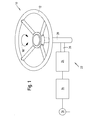
- Fig. 1 shows an embodiment of an operating device 10 according to the invention
- Fig. 1 shown operating device 10 has a steering wheel 12, a control device 14 and a sensor 16.
- the steering wheel 12 can be deflected in two opposite directions (indicated by the double arrow 18).
- operating device 10 controls the direction of travel of the commercial vehicle in that the deflection of the steering wheel 12 in a deflection of a front axle of a in Fig. 2 shown and trained in the form of a tractor agricultural utility vehicle is transferred.
- the operating device 10 further comprises a steering column 20 and an adjusting device 22, which has an actuator 24.
- the actuator 24 has an electric motor, which can be controlled by the control device 14 via a (not separately drawn) power electronics.
- a schematically drawn summation gear 26 is provided for transmitting the torque generated by the electric motor to the steering column 20, a schematically drawn summation gear 26 is provided.
- the actuator 24 acts on the summation 26, the steering wheel 12 with a torque which can act in the clockwise direction or in the opposite direction.
- a not shown sensor is provided, with which the current position of the steering wheel 12 can be determined, which can be fed to the control device 14.
- the sensor 16 detects the travel speed of the commercial vehicle, which is transmitted to the control device 14.
- the adjusting device 22 and thus the actuator 24 are controlled with the control device 14 as a function of the current steering angle in such a way that the steering wheel 12 can be acted upon by a predeterminable changed force.
- a predeterminable changed force This can be a in Fig. 1 not shown operator not optimal or unsafe operating state of the commercial vehicle or the tractor are made perceptible. Accordingly, by applying the steering wheel 12 with a predetermined changed force by the adjusting device 22, the operating characteristic of the steering wheel 12 can be changed.
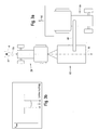
- Fig. 2 shows an agricultural utility vehicle, namely a tractor 28, which the inventive operating device 10 from Fig. 1 having.
- a front loader 30 is adapted, which has a boom 32 and a loader bucket 34.
- the boom 32 of the front loader 30 can be raised or lowered with a double-acting hydraulic cylinder 36.
- a plurality of sensors are arranged, wherein not all sensors for carrying out the present invention are required.
- the sensor 38 of the extension of the piston rod of the hydraulic cylinder 36 can be determined.
- the sensor 40 the change in the volume flow of the hydraulic fluid can be measured, which is supplied to the hydraulic cylinder 36 and which flows from the hydraulic cylinder 36.
- the sensor 42 the present in the piston chamber of the hydraulic cylinder 36 pressure of the hydraulic fluid can be measured.
- the sensor 16 detects the vehicle speed over the ground 60.
- the sensor 46 detects the rotational speed of the left front wheel 48.
- the sensor 50 detects the adjusted steering angle of the front wheel 48.
- the sensor 52 detects the acceleration of the tractor 28.
- the sensor 54 detects the force which is adapted to the tractor 28, in Fig. 2 not shown working device in the tractor 28th initiates.
- the sensor 56 With the sensor 56, the torque transmitted to the rear traction drive can be detected.
- a GPS receiver 58 is provided with which GPS position signals can be received, from which the control unit 14 can determine the current position of the tractor 28. All sensors are connected by means of electrical line connections to the control unit 14 (shown in dashed lines).
- the adjusting device 22 with the in Fig. 2 Not shown actuator connected to the controller 14.
- further sensors may be provided, with which further variables can be detected and from which a corresponding state variable of the commercial vehicle or a work function or from which a state variable of a working device adapted to the commercial vehicle can be derived or determined.
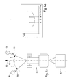
- Fig. 3a shows a trailer consisting of a tractor 28 and a trailer 62.
- a harvester 64 travels in the same direction (indicated by an arrow 66, respectively).
- the harvesting machine 64 has an unloading device 68, with which crop is brought into the trailer 62. During this transfer, it is necessary that the relative position between the trailer 62 and the harvester 64 remains substantially unchanged.
- the reference numeral 70 dashed lines a reference line is shown, with respect to which the trailer 62 to the direction of travel 66 has an ideal or predeterminable relative position.
- the steering angle of the tractor 28 to that of the harvester 64 and to the position of the harvester 64 is adapted. This process is supported by the operating device according to the invention.
- the operating device is implemented in the tractor 28. Accordingly, the steering wheel of the tractor 28 is acted upon by a force whose characteristic curve in the diagram Fig. 3b is shown.
- the force exerted by the actuator on the steering wheel force is plotted relative to the steering angle with respect to the reference line 70. It can be seen from the diagram that in the steering angle range between -A and A a relatively small force is exerted by the actuating device on the steering wheel. This force has the lowest value at 0 and increases slightly or strictly monotonously within the steering angle range.
- the steering angles corresponding to the values -A and A are also in Fig. 3a are drawn in and are intended essentially to characterize the steering angle range in which the transfer operation between harvester 64 and trailer 62 is just possible.
- an operating device can also be provided in the harvesting machine 64.
- Fig. 4a shows a tractor 28 to which a baler 76 is adapted.
- the team consisting of tractor 28 and baler 76, moves along the direction of travel 66.
- a first obstacle 78 which may be in the form of a tree or a (usually not visible in the field) manhole cover.
- a second obstacle 79 which may also be a tree.
- Information about obstacles or other occurrences of the field can be entered, for example, in a program implemented on a computer of the tractor, which is coupled to a navigation system, in a map of the field.
- FIG. 4b shows in a diagram the force exerted on the steering wheel by the actuator force as a function of the steering angle relative to the reference line 80, which in Fig. 4a the straight ahead of the team characterizes. Accordingly, the steering wheel is acted upon by the actuator with increasing steering angle with an increasing force, so that the operator has to apply a greater force to increase the steering angle.
- the steering wheel is acted upon by the actuator with increasing steering angle with an increasing force, so that the operator has to apply a greater force to increase the steering angle.
- the amount of counterforce in the steering angle A or B depends on the distance between the tractor 28 and obstacle 78 and 79. The smaller the distance to the respective obstacle, the greater the force acting on the steering wheel of the actuator counterforce. Accordingly, it can be prevented be that the tractor 28 on the obstacle 78 and 79, respectively.
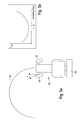
- Fig. 5a shows a tractor 28 to which a plow 82 is adapted.
- the tractor 28 executes a turning process, wherein the desired direction of travel for the turning process is designated by the reference numeral 84.
- the front wheels 48 of the tractor 28 would spend in a steering angle, which in Fig. 5a marked with the angle X.
- Fig. 5b shows in a diagram the force exerted on the steering wheel of the actuator force in response to the steering angle of the front wheels 48 of the tractor 28.
- the force exerted by the actuator to the steering wheel force is minimal.
- the steering wheel is acted upon by the adjusting device with a larger force when a deviating from the steering angle X, larger or smaller steering angle is selected. Accordingly, the operator must apply a greater force to deviate from the steering angle X.
Landscapes
- Engineering & Computer Science (AREA)
- Life Sciences & Earth Sciences (AREA)
- Environmental Sciences (AREA)
- Mechanical Engineering (AREA)
- Human Computer Interaction (AREA)
- Combustion & Propulsion (AREA)
- Chemical & Material Sciences (AREA)
- Transportation (AREA)
- Steering Control In Accordance With Driving Conditions (AREA)
- Non-Deflectable Wheels, Steering Of Trailers, Or Other Steering (AREA)
- Lifting Devices For Agricultural Implements (AREA)
- Harvester Elements (AREA)
- Guiding Agricultural Machines (AREA)
Claims (10)
- Dispositif de commande pour commander au moins une valeur d'état d'un véhicule utilitaire agricole ou industriel, comprenant un volant de direction (12), un système de réglage (22), au moins un capteur (16) et un système de commande (14), le volant de direction (12) pouvant être actionné par un opérateur pour ajuster la direction de conduite du véhicule utilitaire, le volant de direction (12) pouvant être sollicité avec une force par le système de réglage (22), une valeur, qui représente une valeur d'état du véhicule utilitaire (28), pouvant être détectée avec l'au moins un capteur (16) et être transmise au système de commande (14), une valeur d'état d'un état de fonctionnement actuel du véhicule utilitaire (28) pouvant être déterminée avec le système de commande (14), le système de réglage (22) pouvant être commandé avec le système de commande (14) en fonction de l'état de fonctionnement actuel du véhicule utilitaire (28) de telle sorte que le volant de direction (12) puisse être sollicité avec une force modifiée prédéfinissable, afin d'indiquer à l'opérateur un écart par rapport à un état de fonctionnement sûr et/ou optimal du véhicule utilitaire (28) et/ou par rapport à un état de fonctionnement sûr et/ou optimal d'au moins une fonction de travail (30), caractérisé en ce que la prescription de la force modifiée s'effectue au moyen du système de réglage (22) de telle sorte qu'une résistance au mouvement soit conférée au volant de direction (12), laquelle augmente avec la valeur de la différence entre un position instantanée du volant de direction (12) et une position du volant de direction (12) calculée en rapport avec l'état de fonctionnement sûr et/ou optimal du véhicule utilitaire (28) ou de l'au moins une fonction de travail (30).
- Dispositif de commande selon la revendication 1, caractérisé en ce que le système de réglage (22) sollicite le volant de direction (12) avec une courbe de force prédéfinissable, la courbe de force présentant une fonction analytique constante en fonction de l'angle de rotation du volant de direction (12).
- Dispositif de commande selon la revendication 1 ou 2, caractérisé en ce que le système de réglage (22) sollicite le volant de direction (12) se trouvant dans la position neutre ou dans une position quelconque avec une force variable dans le temps.
- Dispositif de commande selon l'une quelconque des revendications 1 à 3, caractérisé en ce que le volant de direction (12) est sollicité avec une force modifiée prédéfinissable lorsque l'état de fonctionnement actuel et/ou une valeur d'état actuelle du véhicule utilitaire (28) ou d'une fonction de travail du véhicule utilitaire (28) est supérieur(e) ou inférieur(e) à une valeur limite prédéfinie.
- Dispositif de commande selon l'une quelconque des revendications 1 à 4, caractérisé en ce que le volant de direction (12) peut être sollicité avec une force prédéterminable, afin d'indiquer à l'opérateur la présence d'un état déterminé d'un appareil de travail (30) adapté au véhicule utilitaire (28).
- Dispositif de commande selon l'une quelconque des revendications 1 à 5, caractérisé en ce que l'on peut conférer au volant de direction (12) une caractéristique de commande prédéfinissable, de telle sorte qu'un opérateur puisse retrouver un ajustement souhaité, une position de braquage ou une plage de braquage du volant de direction (12).
- Dispositif de commande selon l'une quelconque des revendications 1 à 6, caractérisé en ce que le volant de direction (12) peut être sollicité par une force de telle sorte qu'un opérateur évite une plage d'ajustement défavorable d'un état de fonctionnement d'une fonction de travail (30) ou d'une valeur d'état du véhicule utilitaire (28).
- Dispositif de commande selon l'une quelconque des revendications 1 à 7, caractérisé en ce que la force exercée par le système de réglage (22) sur le volant de direction (12) peut être neutralisée ou coupée par l'opérateur.
- Dispositif de commande selon l'une quelconque des revendications 1 à 8, caractérisé en ce qu'en plus de la sollicitation du volant de direction (12) par une force prédéfinissable, un signal visuel et/ou acoustique peut être produit.
- Véhicule utilitaire agricole ou industriel, notamment tracteur, qui présente un dispositif de commande (10) selon l'une quelconque des revendications 1 à 9.
Applications Claiming Priority (1)
| Application Number | Priority Date | Filing Date | Title |
|---|---|---|---|
| DE102007032309A DE102007032309A1 (de) | 2007-07-11 | 2007-07-11 | Bedienvorrichtung |
Publications (2)
| Publication Number | Publication Date |
|---|---|
| EP2014504A1 EP2014504A1 (fr) | 2009-01-14 |
| EP2014504B1 true EP2014504B1 (fr) | 2010-06-30 |
Family
ID=39809712
Family Applications (1)
| Application Number | Title | Priority Date | Filing Date |
|---|---|---|---|
| EP08160006A Active EP2014504B1 (fr) | 2007-07-11 | 2008-07-09 | Dispositif de commande destiné à la commande d'au moins une taille d'état d'un véhicule utilitaire agricole ou industriel |
Country Status (5)
| Country | Link |
|---|---|
| US (1) | US7729830B2 (fr) |
| EP (1) | EP2014504B1 (fr) |
| AT (1) | ATE472434T1 (fr) |
| DE (2) | DE102007032309A1 (fr) |
| ES (1) | ES2347846T3 (fr) |
Cited By (2)
| Publication number | Priority date | Publication date | Assignee | Title |
|---|---|---|---|---|
| DE102013107710A1 (de) * | 2013-07-19 | 2015-02-19 | Claas Saulgau Gmbh | Landwirtschaftliches Zuggespann |
| US12084135B2 (en) | 2018-04-13 | 2024-09-10 | Deere & Company | System and method for influencing steering characteristics |
Families Citing this family (75)
| Publication number | Priority date | Publication date | Assignee | Title |
|---|---|---|---|---|
| US20100311016A1 (en) * | 2008-01-14 | 2010-12-09 | En Technologies Limited | Steering mechanism |
| JP4605265B2 (ja) * | 2008-07-22 | 2011-01-05 | トヨタ自動車株式会社 | 車両の操舵装置 |
| US8311709B2 (en) * | 2009-09-08 | 2012-11-13 | Cnh America Llc | Implement initiated control of tractor power take-off (PTO) |
| DE102010029696A1 (de) * | 2010-06-04 | 2011-12-08 | Raytheon Anschütz Gmbh | Wasserfahrzeug-Steuerung mit aktiver Rückkopplung |
| US20140343697A1 (en) * | 2013-05-17 | 2014-11-20 | Caterpillar Inc. | Selectable Operating Modes for Machine Operator Input Devices |
| US10316492B2 (en) | 2014-07-31 | 2019-06-11 | Cnh Industrial America Llc | Active force/vibration feedback control method and apparatus for a movable machine |
| US9380737B2 (en) * | 2014-08-08 | 2016-07-05 | Deere & Company | Automated re-centering of steering system |
| EP4030378A1 (fr) | 2015-05-10 | 2022-07-20 | Mobileye Vision Technologies Ltd. | Profil de route le long d'un trajet prévu |
| DE102016206126A1 (de) * | 2015-12-16 | 2017-06-22 | Robert Bosch Gmbh | Verfahren und Vorrichtung zum Überwachen oder Regeln einer Fahraufgabe-Übergabe in einem selbstfahrenden Fahrzeug und System für eine Fahraufgabe-Übergabe in einem selbstfahrenden Fahrzeug |
| DE102016216590A1 (de) * | 2016-09-01 | 2018-03-01 | Bayerische Motoren Werke Aktiengesellschaft | Verfahren, Vorrichtung und Computerprogramm zur Erzeugung und Übermittlung einer Fahrerinformation |
| US11279400B1 (en) | 2018-01-02 | 2022-03-22 | RBR Enterprise, LLC | Adjustable wheel track axle with independent wheel angle control for an agricultural vehicle |
| US10525986B2 (en) * | 2018-06-11 | 2020-01-07 | Harman International Industries, Incorporated | System and method for steering wheel haptic notification |
| US20200019192A1 (en) * | 2018-07-13 | 2020-01-16 | Caterpillar Paving Products Inc. | Object detection and implement position detection system |
| US11240961B2 (en) * | 2018-10-26 | 2022-02-08 | Deere & Company | Controlling a harvesting machine based on a geo-spatial representation indicating where the harvesting machine is likely to reach capacity |
| US11467605B2 (en) | 2019-04-10 | 2022-10-11 | Deere & Company | Zonal machine control |
| US11641800B2 (en) | 2020-02-06 | 2023-05-09 | Deere & Company | Agricultural harvesting machine with pre-emergence weed detection and mitigation system |
| US12069978B2 (en) | 2018-10-26 | 2024-08-27 | Deere & Company | Predictive environmental characteristic map generation and control system |
| US11079725B2 (en) | 2019-04-10 | 2021-08-03 | Deere & Company | Machine control using real-time model |
| US11672203B2 (en) | 2018-10-26 | 2023-06-13 | Deere & Company | Predictive map generation and control |
| US11957072B2 (en) | 2020-02-06 | 2024-04-16 | Deere & Company | Pre-emergence weed detection and mitigation system |
| US11178818B2 (en) | 2018-10-26 | 2021-11-23 | Deere & Company | Harvesting machine control system with fill level processing based on yield data |
| US11653588B2 (en) | 2018-10-26 | 2023-05-23 | Deere & Company | Yield map generation and control system |
| US11589509B2 (en) | 2018-10-26 | 2023-02-28 | Deere & Company | Predictive machine characteristic map generation and control system |
| US11234366B2 (en) | 2019-04-10 | 2022-02-01 | Deere & Company | Image selection for machine control |
| US11778945B2 (en) | 2019-04-10 | 2023-10-10 | Deere & Company | Machine control using real-time model |
| KR102808602B1 (ko) * | 2019-09-11 | 2025-05-20 | 에이치엘만도 주식회사 | 조향 제어 장치 및 그 방법, 그리고 조향 시스템 |
| US12329148B2 (en) | 2020-02-06 | 2025-06-17 | Deere & Company | Predictive weed map and material application machine control |
| US12035648B2 (en) | 2020-02-06 | 2024-07-16 | Deere & Company | Predictive weed map generation and control system |
| US12225846B2 (en) | 2020-02-06 | 2025-02-18 | Deere & Company | Machine control using a predictive map |
| US12016257B2 (en) | 2020-02-19 | 2024-06-25 | Sabanto, Inc. | Methods for detecting and clearing debris from planter gauge wheels, closing wheels and seed tubes |
| US11477940B2 (en) | 2020-03-26 | 2022-10-25 | Deere & Company | Mobile work machine control based on zone parameter modification |
| US12461083B2 (en) | 2020-08-03 | 2025-11-04 | Sabanto, Inc. | Methods for improved agricultural procedures |
| US11874669B2 (en) | 2020-10-09 | 2024-01-16 | Deere & Company | Map generation and control system |
| US11844311B2 (en) | 2020-10-09 | 2023-12-19 | Deere & Company | Machine control using a predictive map |
| US12013245B2 (en) | 2020-10-09 | 2024-06-18 | Deere & Company | Predictive map generation and control system |
| US11711995B2 (en) | 2020-10-09 | 2023-08-01 | Deere & Company | Machine control using a predictive map |
| US11983009B2 (en) | 2020-10-09 | 2024-05-14 | Deere & Company | Map generation and control system |
| US11727680B2 (en) | 2020-10-09 | 2023-08-15 | Deere & Company | Predictive map generation based on seeding characteristics and control |
| US11946747B2 (en) | 2020-10-09 | 2024-04-02 | Deere & Company | Crop constituent map generation and control system |
| US12178158B2 (en) | 2020-10-09 | 2024-12-31 | Deere & Company | Predictive map generation and control system for an agricultural work machine |
| US12386354B2 (en) | 2020-10-09 | 2025-08-12 | Deere & Company | Predictive power map generation and control system |
| US12069986B2 (en) | 2020-10-09 | 2024-08-27 | Deere & Company | Map generation and control system |
| US11592822B2 (en) | 2020-10-09 | 2023-02-28 | Deere & Company | Machine control using a predictive map |
| US11675354B2 (en) | 2020-10-09 | 2023-06-13 | Deere & Company | Machine control using a predictive map |
| US12419220B2 (en) | 2020-10-09 | 2025-09-23 | Deere & Company | Predictive map generation and control system |
| US11895948B2 (en) | 2020-10-09 | 2024-02-13 | Deere & Company | Predictive map generation and control based on soil properties |
| US11849671B2 (en) | 2020-10-09 | 2023-12-26 | Deere & Company | Crop state map generation and control system |
| US12422847B2 (en) | 2020-10-09 | 2025-09-23 | Deere & Company | Predictive agricultural model and map generation |
| US12550802B2 (en) | 2020-10-08 | 2026-02-17 | Deere & Company | Predictive machine characteristic map generation and control system |
| US11650587B2 (en) | 2020-10-09 | 2023-05-16 | Deere & Company | Predictive power map generation and control system |
| US11635765B2 (en) | 2020-10-09 | 2023-04-25 | Deere & Company | Crop state map generation and control system |
| US11927459B2 (en) | 2020-10-09 | 2024-03-12 | Deere & Company | Machine control using a predictive map |
| US11871697B2 (en) | 2020-10-09 | 2024-01-16 | Deere & Company | Crop moisture map generation and control system |
| US11889788B2 (en) | 2020-10-09 | 2024-02-06 | Deere & Company | Predictive biomass map generation and control |
| US11474523B2 (en) | 2020-10-09 | 2022-10-18 | Deere & Company | Machine control using a predictive speed map |
| US11849672B2 (en) | 2020-10-09 | 2023-12-26 | Deere & Company | Machine control using a predictive map |
| US11845449B2 (en) | 2020-10-09 | 2023-12-19 | Deere & Company | Map generation and control system |
| US11825768B2 (en) | 2020-10-09 | 2023-11-28 | Deere & Company | Machine control using a predictive map |
| US11864483B2 (en) | 2020-10-09 | 2024-01-09 | Deere & Company | Predictive map generation and control system |
| US11889787B2 (en) | 2020-10-09 | 2024-02-06 | Deere & Company | Predictive speed map generation and control system |
| US12250905B2 (en) | 2020-10-09 | 2025-03-18 | Deere & Company | Machine control using a predictive map |
| US12127500B2 (en) | 2021-01-27 | 2024-10-29 | Deere & Company | Machine control using a map with regime zones |
| US12229886B2 (en) | 2021-10-01 | 2025-02-18 | Deere & Company | Historical crop state model, predictive crop state map generation and control system |
| US12310286B2 (en) | 2021-12-14 | 2025-05-27 | Deere & Company | Crop constituent sensing |
| US12302791B2 (en) | 2021-12-20 | 2025-05-20 | Deere & Company | Crop constituents, predictive mapping, and agricultural harvester control |
| US12245549B2 (en) | 2022-01-11 | 2025-03-11 | Deere & Company | Predictive response map generation and control system |
| US12082531B2 (en) | 2022-01-26 | 2024-09-10 | Deere & Company | Systems and methods for predicting material dynamics |
| US12520759B2 (en) | 2022-01-26 | 2026-01-13 | Deere & Company | Systems and methods for predicting material dynamics |
| US12295288B2 (en) | 2022-04-05 | 2025-05-13 | Deere &Company | Predictive machine setting map generation and control system |
| US12582035B2 (en) | 2022-04-08 | 2026-03-24 | Deere & Company | Systems and methods for predictive power requirements and control |
| US12058951B2 (en) | 2022-04-08 | 2024-08-13 | Deere & Company | Predictive nutrient map and control |
| US12358493B2 (en) | 2022-04-08 | 2025-07-15 | Deere & Company | Systems and methods for predictive power requirements and control |
| US12284934B2 (en) | 2022-04-08 | 2025-04-29 | Deere & Company | Systems and methods for predictive tractive characteristics and control |
| US12298767B2 (en) | 2022-04-08 | 2025-05-13 | Deere & Company | Predictive material consumption map and control |
| US11884324B2 (en) * | 2022-05-20 | 2024-01-30 | Steering Solutions Ip Holding Corporation | Systems and methods for inducing speed reduction responsive to detecting a surface having a relatively low coefficient of friction |
Family Cites Families (20)
| Publication number | Priority date | Publication date | Assignee | Title |
|---|---|---|---|---|
| JPH05105100A (ja) * | 1991-09-27 | 1993-04-27 | Honda Motor Co Ltd | 車両の操舵装置 |
| US5636909A (en) * | 1993-12-01 | 1997-06-10 | Mazda Motor Corporation | Traction control system for vehicle |
| US5735584A (en) * | 1994-11-25 | 1998-04-07 | Itt Automotive Europe Gmbh | Process for driving stability control with control via pressure gradients |
| DE19526250B4 (de) * | 1995-07-18 | 2005-02-17 | Daimlerchrysler Ag | Brems- und Lenksystem für ein Fahrzeug |
| JPH0966851A (ja) * | 1995-08-31 | 1997-03-11 | Mitsubishi Electric Corp | 車両用制御装置 |
| IT1291484B1 (it) | 1997-01-31 | 1999-01-11 | Fiat Ricerche | Dispositivo di segnalazione interna per un autoveicolo. |
| US6705685B1 (en) * | 1998-04-24 | 2004-03-16 | Continental Teves Ag & Co. Ohg | Method and device for controlling the traction slip of a vehicle with a high coefficient of friction |
| WO2000005124A1 (fr) * | 1998-07-21 | 2000-02-03 | Techco Corporation | Retroaction et commande asservie pour systemes electriques de direction assistee |
| DE19904626C2 (de) | 1999-02-05 | 2001-05-17 | Case Harvesting Sys Gmbh | Verfahren zum Erkennen von Fremdkörpern in Erntemaschinen |
| EP1159173B1 (fr) * | 1999-02-27 | 2006-02-22 | Continental Teves AG & Co. oHG | Procede de regulation du comportement routier d'un vehicule |
| DE19923012A1 (de) * | 1999-05-20 | 2000-11-23 | Zahnradfabrik Friedrichshafen | Lenkvorrichtung und Lenkverfahren |
| US6523635B1 (en) * | 1999-11-02 | 2003-02-25 | Deere & Company | Steering and ground speed control mechanism of a dual-path hydrostatic drive system |
| JP2004527413A (ja) * | 2001-03-20 | 2004-09-09 | コンティネンタル・テーベス・アクチエンゲゼルシヤフト・ウント・コンパニー・オッフェネ・ハンデルスゲゼルシヤフト | 制御される自動車ブレーキシステムの制御応答を改善する方法 |
| DE10209206A1 (de) * | 2002-03-04 | 2003-09-25 | Siemens Ag | Warnvorrichtung |
| US6695092B2 (en) * | 2002-03-04 | 2004-02-24 | Delphi Technologies, Inc. | Steering actuator system |
| US6694239B1 (en) * | 2002-12-17 | 2004-02-17 | Visteon Global Technologies, Inc. | System and method of controlling vehicle steer-by-wire systems |
| CA2427416C (fr) * | 2003-05-01 | 2010-11-16 | 101039130 Saskatchewan Ltd. | Dispositif de direction pour outils remorques |
| JP4058389B2 (ja) * | 2003-06-26 | 2008-03-05 | トヨタ自動車株式会社 | 車両用走行支援装置 |
| US7004279B2 (en) * | 2003-08-28 | 2006-02-28 | Nissan Motor Co., Ltd. | Vehicle steering system |
| ATE390313T1 (de) | 2005-10-19 | 2008-04-15 | Fiat Ricerche | Haptische anzeige umfassend ein gaspedal für ein kraftfahrzeug |
-
2007
- 2007-07-11 DE DE102007032309A patent/DE102007032309A1/de not_active Withdrawn
-
2008
- 2008-06-09 US US12/135,658 patent/US7729830B2/en active Active
- 2008-07-09 ES ES08160006T patent/ES2347846T3/es active Active
- 2008-07-09 DE DE502008000861T patent/DE502008000861D1/de active Active
- 2008-07-09 EP EP08160006A patent/EP2014504B1/fr active Active
- 2008-07-09 AT AT08160006T patent/ATE472434T1/de active
Cited By (3)
| Publication number | Priority date | Publication date | Assignee | Title |
|---|---|---|---|---|
| DE102013107710A1 (de) * | 2013-07-19 | 2015-02-19 | Claas Saulgau Gmbh | Landwirtschaftliches Zuggespann |
| DE102013107710B4 (de) * | 2013-07-19 | 2021-05-27 | Claas Saulgau Gmbh | Landwirtschaftliches Zuggespann und Assistenzsystem eines landwirtschaftlichen Zuggespanns |
| US12084135B2 (en) | 2018-04-13 | 2024-09-10 | Deere & Company | System and method for influencing steering characteristics |
Also Published As
| Publication number | Publication date |
|---|---|
| US7729830B2 (en) | 2010-06-01 |
| DE102007032309A1 (de) | 2009-01-15 |
| DE502008000861D1 (de) | 2010-08-12 |
| US20090143941A1 (en) | 2009-06-04 |
| ES2347846T3 (es) | 2010-11-04 |
| EP2014504A1 (fr) | 2009-01-14 |
| ATE472434T1 (de) | 2010-07-15 |
Similar Documents
| Publication | Publication Date | Title |
|---|---|---|
| EP2014504B1 (fr) | Dispositif de commande destiné à la commande d'au moins une taille d'état d'un véhicule utilitaire agricole ou industriel | |
| EP2014503B1 (fr) | Dispositif de commande destiné à la commande d'au moins une taille d'état d'un véhicule utilitaire agricole ou industriel | |
| EP1988222B1 (fr) | Dispositif de commande | |
| DE102007029413B4 (de) | Verfahren zur Durchführung eines Lenkvorganges in einem Fahrzeug mit Anhänger bei Rückwärtsfahrt | |
| EP1987970B1 (fr) | Système de déplacement actif pour véhicule agricole ou industriel | |
| EP2586282B1 (fr) | Agencement pour direction automatique d'une combinaison à partir d'un véhicule automobile et un appareil destiné aux travaux des champs | |
| EP2022306B1 (fr) | Système de commande destiné à la conduite d'un élément auxiliaire couplé à un véhicule utilitaire agricole | |
| EP2621257B1 (fr) | Combinaison constituée d'un véhicule tracteur et d'un appareil | |
| EP2879938B1 (fr) | Procédé et appareil pour garer un remorque | |
| EP2757867B2 (fr) | Véhicule pouvant être dirigé | |
| EP1419683B1 (fr) | Methode de commande d'un vehicule agricole | |
| EP2022702B1 (fr) | Véhicule doté de roues avant et arrière orientables | |
| DE102014118229A1 (de) | Lenksystem für ein landwirtschaftliches Fahrzeug | |
| EP2818337A1 (fr) | Véhicule agricole | |
| DE102020209832A1 (de) | Knickgelenktes arbeitsfahrzeug mit lenkungsauswahl | |
| DE102022210683A1 (de) | Lenksystem mit mehreren wählbaren anwendungsmodi und verfahren dafür | |
| DE102022210458A1 (de) | Lenksystem mit mehreren wählbaren anwendungsmodi und verfahren dafür | |
| EP1488676B1 (fr) | Moissonneuse automotrice | |
| DE10138563B4 (de) | Rad-Straßenfertiger und Verfahren zum Lenken eines Rad-Straßenfertigers | |
| EP3556641B1 (fr) | Procédé d'influence des caractéristiques de direction d'un tracteur agricole | |
| EP3231688B1 (fr) | Véhicule agricole | |
| EP4147553A1 (fr) | Système de commande permettant de diriger une machine de travail agricole | |
| WO2017186662A1 (fr) | Système assisté par caméra pour la sélection de destinations et le guidage d'un véhicule | |
| EP4272531A1 (fr) | Machine agricole automotrice |
Legal Events
| Date | Code | Title | Description |
|---|---|---|---|
| PUAI | Public reference made under article 153(3) epc to a published international application that has entered the european phase |
Free format text: ORIGINAL CODE: 0009012 |
|
| AK | Designated contracting states |
Kind code of ref document: A1 Designated state(s): AT BE BG CH CY CZ DE DK EE ES FI FR GB GR HR HU IE IS IT LI LT LU LV MC MT NL NO PL PT RO SE SI SK TR |
|
| AX | Request for extension of the european patent |
Extension state: AL BA MK RS |
|
| 17P | Request for examination filed |
Effective date: 20090714 |
|
| 17Q | First examination report despatched |
Effective date: 20090807 |
|
| AKX | Designation fees paid |
Designated state(s): AT BE BG CH CY CZ DE DK EE ES FI FR GB GR HR HU IE IS IT LI LT LU LV MC MT NL NO PL PT RO SE SI SK TR |
|
| GRAP | Despatch of communication of intention to grant a patent |
Free format text: ORIGINAL CODE: EPIDOSNIGR1 |
|
| GRAC | Information related to communication of intention to grant a patent modified |
Free format text: ORIGINAL CODE: EPIDOSCIGR1 |
|
| GRAS | Grant fee paid |
Free format text: ORIGINAL CODE: EPIDOSNIGR3 |
|
| GRAA | (expected) grant |
Free format text: ORIGINAL CODE: 0009210 |
|
| AK | Designated contracting states |
Kind code of ref document: B1 Designated state(s): AT BE BG CH CY CZ DE DK EE ES FI FR GB GR HR HU IE IS IT LI LT LU LV MC MT NL NO PL PT RO SE SI SK TR |
|
| REG | Reference to a national code |
Ref country code: CH Ref legal event code: EP Ref country code: GB Ref legal event code: FG4D Free format text: NOT ENGLISH |
|
| REG | Reference to a national code |
Ref country code: IE Ref legal event code: FG4D Free format text: LANGUAGE OF EP DOCUMENT: GERMAN |
|
| REF | Corresponds to: |
Ref document number: 502008000861 Country of ref document: DE Date of ref document: 20100812 Kind code of ref document: P |
|
| REG | Reference to a national code |
Ref country code: NL Ref legal event code: VDEP Effective date: 20100630 |
|
| PG25 | Lapsed in a contracting state [announced via postgrant information from national office to epo] |
Ref country code: NO Free format text: LAPSE BECAUSE OF FAILURE TO SUBMIT A TRANSLATION OF THE DESCRIPTION OR TO PAY THE FEE WITHIN THE PRESCRIBED TIME-LIMIT Effective date: 20100930 Ref country code: SE Free format text: LAPSE BECAUSE OF FAILURE TO SUBMIT A TRANSLATION OF THE DESCRIPTION OR TO PAY THE FEE WITHIN THE PRESCRIBED TIME-LIMIT Effective date: 20100630 Ref country code: LT Free format text: LAPSE BECAUSE OF FAILURE TO SUBMIT A TRANSLATION OF THE DESCRIPTION OR TO PAY THE FEE WITHIN THE PRESCRIBED TIME-LIMIT Effective date: 20100630 |
|
| REG | Reference to a national code |
Ref country code: ES Ref legal event code: FG2A Ref document number: 2347846 Country of ref document: ES Kind code of ref document: T3 |
|
| LTIE | Lt: invalidation of european patent or patent extension |
Effective date: 20100630 |
|
| PG25 | Lapsed in a contracting state [announced via postgrant information from national office to epo] |
Ref country code: HR Free format text: LAPSE BECAUSE OF FAILURE TO SUBMIT A TRANSLATION OF THE DESCRIPTION OR TO PAY THE FEE WITHIN THE PRESCRIBED TIME-LIMIT Effective date: 20100630 Ref country code: LV Free format text: LAPSE BECAUSE OF FAILURE TO SUBMIT A TRANSLATION OF THE DESCRIPTION OR TO PAY THE FEE WITHIN THE PRESCRIBED TIME-LIMIT Effective date: 20100630 Ref country code: SI Free format text: LAPSE BECAUSE OF FAILURE TO SUBMIT A TRANSLATION OF THE DESCRIPTION OR TO PAY THE FEE WITHIN THE PRESCRIBED TIME-LIMIT Effective date: 20100630 |
|
| PG25 | Lapsed in a contracting state [announced via postgrant information from national office to epo] |
Ref country code: PL Free format text: LAPSE BECAUSE OF FAILURE TO SUBMIT A TRANSLATION OF THE DESCRIPTION OR TO PAY THE FEE WITHIN THE PRESCRIBED TIME-LIMIT Effective date: 20100630 |
|
| BERE | Be: lapsed |
Owner name: DEERE & CY Effective date: 20100731 |
|
| PG25 | Lapsed in a contracting state [announced via postgrant information from national office to epo] |
Ref country code: NL Free format text: LAPSE BECAUSE OF FAILURE TO SUBMIT A TRANSLATION OF THE DESCRIPTION OR TO PAY THE FEE WITHIN THE PRESCRIBED TIME-LIMIT Effective date: 20100630 Ref country code: EE Free format text: LAPSE BECAUSE OF FAILURE TO SUBMIT A TRANSLATION OF THE DESCRIPTION OR TO PAY THE FEE WITHIN THE PRESCRIBED TIME-LIMIT Effective date: 20100630 |
|
| REG | Reference to a national code |
Ref country code: IE Ref legal event code: FD4D |
|
| PG25 | Lapsed in a contracting state [announced via postgrant information from national office to epo] |
Ref country code: CY Free format text: LAPSE BECAUSE OF FAILURE TO SUBMIT A TRANSLATION OF THE DESCRIPTION OR TO PAY THE FEE WITHIN THE PRESCRIBED TIME-LIMIT Effective date: 20100630 Ref country code: RO Free format text: LAPSE BECAUSE OF FAILURE TO SUBMIT A TRANSLATION OF THE DESCRIPTION OR TO PAY THE FEE WITHIN THE PRESCRIBED TIME-LIMIT Effective date: 20100630 Ref country code: SK Free format text: LAPSE BECAUSE OF FAILURE TO SUBMIT A TRANSLATION OF THE DESCRIPTION OR TO PAY THE FEE WITHIN THE PRESCRIBED TIME-LIMIT Effective date: 20100630 Ref country code: MC Free format text: LAPSE BECAUSE OF NON-PAYMENT OF DUE FEES Effective date: 20100731 Ref country code: IS Free format text: LAPSE BECAUSE OF FAILURE TO SUBMIT A TRANSLATION OF THE DESCRIPTION OR TO PAY THE FEE WITHIN THE PRESCRIBED TIME-LIMIT Effective date: 20101030 Ref country code: CZ Free format text: LAPSE BECAUSE OF FAILURE TO SUBMIT A TRANSLATION OF THE DESCRIPTION OR TO PAY THE FEE WITHIN THE PRESCRIBED TIME-LIMIT Effective date: 20100630 |
|
| PG25 | Lapsed in a contracting state [announced via postgrant information from national office to epo] |
Ref country code: IE Free format text: LAPSE BECAUSE OF FAILURE TO SUBMIT A TRANSLATION OF THE DESCRIPTION OR TO PAY THE FEE WITHIN THE PRESCRIBED TIME-LIMIT Effective date: 20100630 Ref country code: DK Free format text: LAPSE BECAUSE OF FAILURE TO SUBMIT A TRANSLATION OF THE DESCRIPTION OR TO PAY THE FEE WITHIN THE PRESCRIBED TIME-LIMIT Effective date: 20100630 |
|
| PLBE | No opposition filed within time limit |
Free format text: ORIGINAL CODE: 0009261 |
|
| STAA | Information on the status of an ep patent application or granted ep patent |
Free format text: STATUS: NO OPPOSITION FILED WITHIN TIME LIMIT |
|
| PG25 | Lapsed in a contracting state [announced via postgrant information from national office to epo] |
Ref country code: GR Free format text: LAPSE BECAUSE OF FAILURE TO SUBMIT A TRANSLATION OF THE DESCRIPTION OR TO PAY THE FEE WITHIN THE PRESCRIBED TIME-LIMIT Effective date: 20101001 |
|
| 26N | No opposition filed |
Effective date: 20110331 |
|
| PG25 | Lapsed in a contracting state [announced via postgrant information from national office to epo] |
Ref country code: BE Free format text: LAPSE BECAUSE OF NON-PAYMENT OF DUE FEES Effective date: 20100731 |
|
| REG | Reference to a national code |
Ref country code: DE Ref legal event code: R097 Ref document number: 502008000861 Country of ref document: DE Effective date: 20110330 |
|
| PG25 | Lapsed in a contracting state [announced via postgrant information from national office to epo] |
Ref country code: MT Free format text: LAPSE BECAUSE OF FAILURE TO SUBMIT A TRANSLATION OF THE DESCRIPTION OR TO PAY THE FEE WITHIN THE PRESCRIBED TIME-LIMIT Effective date: 20100630 |
|
| PG25 | Lapsed in a contracting state [announced via postgrant information from national office to epo] |
Ref country code: LU Free format text: LAPSE BECAUSE OF NON-PAYMENT OF DUE FEES Effective date: 20100709 Ref country code: PT Free format text: LAPSE BECAUSE OF FAILURE TO SUBMIT A TRANSLATION OF THE DESCRIPTION OR TO PAY THE FEE WITHIN THE PRESCRIBED TIME-LIMIT Effective date: 20101130 Ref country code: HU Free format text: LAPSE BECAUSE OF FAILURE TO SUBMIT A TRANSLATION OF THE DESCRIPTION OR TO PAY THE FEE WITHIN THE PRESCRIBED TIME-LIMIT Effective date: 20110101 Ref country code: BG Free format text: LAPSE BECAUSE OF FAILURE TO SUBMIT A TRANSLATION OF THE DESCRIPTION OR TO PAY THE FEE WITHIN THE PRESCRIBED TIME-LIMIT Effective date: 20100630 |
|
| PG25 | Lapsed in a contracting state [announced via postgrant information from national office to epo] |
Ref country code: TR Free format text: LAPSE BECAUSE OF FAILURE TO SUBMIT A TRANSLATION OF THE DESCRIPTION OR TO PAY THE FEE WITHIN THE PRESCRIBED TIME-LIMIT Effective date: 20100630 |
|
| REG | Reference to a national code |
Ref country code: CH Ref legal event code: PL |
|
| PG25 | Lapsed in a contracting state [announced via postgrant information from national office to epo] |
Ref country code: LI Free format text: LAPSE BECAUSE OF NON-PAYMENT OF DUE FEES Effective date: 20120731 Ref country code: CH Free format text: LAPSE BECAUSE OF NON-PAYMENT OF DUE FEES Effective date: 20120731 |
|
| PG25 | Lapsed in a contracting state [announced via postgrant information from national office to epo] |
Ref country code: BG Free format text: LAPSE BECAUSE OF FAILURE TO SUBMIT A TRANSLATION OF THE DESCRIPTION OR TO PAY THE FEE WITHIN THE PRESCRIBED TIME-LIMIT Effective date: 20100930 |
|
| REG | Reference to a national code |
Ref country code: FR Ref legal event code: PLFP Year of fee payment: 9 |
|
| REG | Reference to a national code |
Ref country code: FR Ref legal event code: PLFP Year of fee payment: 10 |
|
| REG | Reference to a national code |
Ref country code: FR Ref legal event code: PLFP Year of fee payment: 11 |
|
| PGFP | Annual fee paid to national office [announced via postgrant information from national office to epo] |
Ref country code: ES Payment date: 20250801 Year of fee payment: 18 Ref country code: FI Payment date: 20250725 Year of fee payment: 18 |
|
| PGFP | Annual fee paid to national office [announced via postgrant information from national office to epo] |
Ref country code: DE Payment date: 20250620 Year of fee payment: 18 |
|
| PGFP | Annual fee paid to national office [announced via postgrant information from national office to epo] |
Ref country code: IT Payment date: 20250721 Year of fee payment: 18 |
|
| PGFP | Annual fee paid to national office [announced via postgrant information from national office to epo] |
Ref country code: GB Payment date: 20250728 Year of fee payment: 18 |
|
| PGFP | Annual fee paid to national office [announced via postgrant information from national office to epo] |
Ref country code: AT Payment date: 20250620 Year of fee payment: 18 Ref country code: FR Payment date: 20250725 Year of fee payment: 18 |