EP2116151A2 - Einstellbare Mattentrageunterlage mit Spiralbewehrung mit Verfangschutz - Google Patents
Einstellbare Mattentrageunterlage mit Spiralbewehrung mit Verfangschutz Download PDFInfo
- Publication number
- EP2116151A2 EP2116151A2 EP20090159560 EP09159560A EP2116151A2 EP 2116151 A2 EP2116151 A2 EP 2116151A2 EP 20090159560 EP20090159560 EP 20090159560 EP 09159560 A EP09159560 A EP 09159560A EP 2116151 A2 EP2116151 A2 EP 2116151A2
- Authority
- EP
- European Patent Office
- Prior art keywords
- upper frame
- supporting base
- longitudinal sections
- mattress supporting
- spiral
- Prior art date
- Legal status (The legal status is an assumption and is not a legal conclusion. Google has not performed a legal analysis and makes no representation as to the accuracy of the status listed.)
- Granted
Links
- 230000008878 coupling Effects 0.000 claims description 6
- 238000010168 coupling process Methods 0.000 claims description 6
- 238000005859 coupling reaction Methods 0.000 claims description 6
- 229920001971 elastomer Polymers 0.000 claims description 5
- 239000005060 rubber Substances 0.000 claims description 5
- 230000002745 absorbent Effects 0.000 claims description 2
- 239000002250 absorbent Substances 0.000 claims description 2
- 239000000463 material Substances 0.000 claims description 2
- 239000007779 soft material Substances 0.000 claims description 2
- 210000002414 leg Anatomy 0.000 description 6
- 238000010276 construction Methods 0.000 description 2
- 230000002411 adverse Effects 0.000 description 1
- 239000013013 elastic material Substances 0.000 description 1
- 230000002708 enhancing effect Effects 0.000 description 1
- 210000000629 knee joint Anatomy 0.000 description 1
- 230000008092 positive effect Effects 0.000 description 1
Images

Classifications
-
- A—HUMAN NECESSITIES
- A47—FURNITURE; DOMESTIC ARTICLES OR APPLIANCES; COFFEE MILLS; SPICE MILLS; SUCTION CLEANERS IN GENERAL
- A47C—CHAIRS; SOFAS; BEDS
- A47C20/00—Head-, foot- or like rests for beds, sofas or the like
- A47C20/04—Head-, foot- or like rests for beds, sofas or the like with adjustable inclination
-
- A—HUMAN NECESSITIES
- A47—FURNITURE; DOMESTIC ARTICLES OR APPLIANCES; COFFEE MILLS; SPICE MILLS; SUCTION CLEANERS IN GENERAL
- A47C—CHAIRS; SOFAS; BEDS
- A47C23/00—Spring mattresses with rigid frame or forming part of the bedstead, e.g. box springs; Divan bases; Slatted bed bases
- A47C23/12—Spring mattresses with rigid frame or forming part of the bedstead, e.g. box springs; Divan bases; Slatted bed bases using tensioned springs, e.g. flat type
- A47C23/26—Frames therefor; Connecting the springs to the frame
Definitions
- the invention relates to a spiral mattress supporting base, comprising a fixed lower frame, an upper frame which is mounted directly onto the lower frame and which comprises movable upper frame members, as well as supporting means by means of which at least a portion of the upper frame is supported by the lower frame, which upper frame consists of longitudinal sections disposed transversely at a fixed distance in relation to one another, and traverse members extending between the longitudinal sections, between which upper longitudinal sections a network of interlocked helical springs is spanned, which lower frame consists of lower longitudinal sections which are at a fixed distance in relation to one another in transverse direction.
- Such a spiral mattress supporting base is known in the prior art.
- the longitudinal sections thereof and possibly the cross-sections at the longitudinal ends thereof, which are in full view, usually have a slim line form that must be advantageous to the design of the spiral mattress support.
- the longitudinal sections of the upper mattress are positioned directly on top of the longitudinal sections of the lower mattress in an effort to retain the general impression of a slim line construction.
- a mattress may subsequently be placed upon the upper frame.
- the upper frame between which the diagonally spanned helical springs are fastened may also be constructed as part of a so-called "box spring". In that case, a lower mattress is attached to the upper frame, upon which lower mattress further upper mattresses may be placed.
- a further drawback related to the sections that lie one on top of the other relates to the comfort of the spiral mattress supporting base.
- the control means of the movable upper frame members which control means are usually located on a lateral side of the spiral mattress supporting base and attached to a longitudinal section.
- trapping could subsequently occur.
- Such a problem may also arise when two spiral mattress supporting bases are set up adjacent to one another, wherein the user of the one spiral mattress supporting base is exposed to the risk of trapping if the user of the one spiral mattress supporting base operates the movable upper frame members of the other spiral mattress supporting base.
- the object of the invention therefore is to provide a spiral mattress supporting base of the kind referred to in the foregoing, which does not have these drawbacks. That goal is achieved due to the fact that the transverse distance between the lower longitudinal sections is smaller than the transverse distance between the upper longitudinal sections and due to the fact that the supporting means engage from a distance within the outer ends of at least one of the traverse members, such that the sections of the lower frame and upper frame no longer rest upon each other. Furthermore, the supporting means are moved inwardly relative to the longitudinal sections of the upper frame members, so that these are hidden from view and no longer expose anyone to the risk of trapping.
- a lower frame and an upper frame are present.
- the longitudinal sections thereof are laterally displaced relative to each other in such a manner that they remain at a considerable distance from one another, even when the movable upper frame members are folded down.
- the risk of trapping is considerably reduced or even prevented.
- such an offset arrangement of the longitudinal sections leads to the lower frame remaining largely out of view, which works to the advantage of the overall appearance of the spiral mattress supporting base.
- the lower frame may then be constructed less luxuriously and less expensive without this affecting the general quality impression of the spiral mattress supporting base.
- the same positive effect can be achieved at the level of the head end and foot end of the spiral mattress supporting base.
- provisions can be made so that the distance between the outermost lower transverse sections is smaller than the distance between the outermost upper transverse sections.
- the lower frame is also better hidden from view, while the risk of trapping is prevented.
- the upper frame rests upon the lower frame.
- the adjustable upper frame members also rest upon the lower frame, wherein, in accordance with the prior art, the longitudinal sections rest precisely on top of one another. In an offset position of the longitudinal sections in relation to one another, such a direct support is more difficult to achieve, or impossible. It is for this reason that, according to the invention, the spiral mattress supporting base is constructed in such a manner that at least one of the traverse members and/or the lower longitudinal sections are provided with or bear supporting means.
- the support function of the lower frame is achieved by using the transverse members, which cross transversely over the lower longitudinal sections of the lower frame. In the most extreme downwardly moved position of the movable upper frame members, the traverse members rest upon the lower longitudinal sections, thus ensuring an excellent support.
- This support can be obtained in numerous ways. This means that it is also important that the support be sturdy and noise-free. This can be achieved if at least one of the traverse members bears a downwardly directed support which engages with or across a lower longitudinal section.
- the support preferably consists of an absorbent material, such as rubber.
- the supporting means are arranged upon the movable upper frame members, and in such a position that they are aligned relative to the corresponding longitudinal section of the lower frame.
- the upper frame may comprise an upper frame section mounted in a fixed position upon the lower frame.
- at least one of the movable upper frame members is constructed articulated.
- the articulated upper frame member may be arranged at the foot end, so that the guide hinge is disposed approximately at the same height of the user's knee joint.
- the upper frame member arranged at the head end may also be articulated.
- Each of the articulated movable upper frame members comprise two members hingeably attached to one another, each comprising two traverse members disposed at a fixed distance in relation to one another in a longitudinal direction. These traverse members are each provided with supports, so that a stable support is ensured for each individual member.
- the circumference of the upper frame may bear an edge trim formed from a soft or elastic material.
- Such an elastic edge trim may guard against the risk of trapping in the case of two spiral mattress supporting bases being placed next to one another.
- the lower frame is preferably supported on the floor by legs.
- Such legs can be fastened to the lower longitudinal sections and/or to the lower transverse sections.
- legs are attached to the four corners of the lower frame of single spiral mattress supporting bases.
- the jointly coupled spiral mattress supporting bases form a single sturdy whole on the corners of which four feet suffice.
- the supporting means engage at a distance within the outer ends of the traverse members.
- the supporting means may be constructed as stops which operate in the most downwardly moved position of the movable members of the upper mattress and then rest upon one another. This means that a support attached to the upper frame member lies in abutment with a longitudinal section of the lower frame, or conversely, that a support attached to the lower frame lies in abutment with the upper frame member. Also, a support attached to the upper frame member may lie in abutment with a support attached to the lower frame.
- the movable upper frame members can be adjusted by control means or by adjusting and securing means, for example in the form of a lever with a plunger/cylinder device. In the raised position of the upper frame members, these may be stabilized using said control means. It is also possible to only apply securing means which lock the upper frame members in a desired position, after these have been manually adjusted.
- the invention further relates to a box spring, comprising a spiral mattress supporting base, as described in the foregoing, as well as a fixed box spring mattress attached to the spiral mattress supporting base.
- the box spring mattress may comprise a circumferential element surrounding the outermost sections of the upper frame.
- the box spring mattress may comprise a lower mattress.
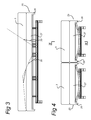
- the spiral mattress shown in figures 1, 2 and 6 comprises a fixed lower frame 1 and, in its entirety, the lower frame indicated by the numeral 2.
- the upper mattress 3 is shown schematically on top of the upper frame 2.
- the upper frame 2 comprises the movable upper frame members 4, 5 and 6.
- the movable upper frame member 4 which is intended for supporting the body is attached by means of a hinge 8 to the fixed upper frame member 7. Further to this, the movable upper frame member 5 is attached to said upper frame member 7 by hinge 9
- the further upper frame member 6 is attached by hinge 10 at the other end of the fixed upper frame member 7.
- the upper frame members 5 and 6 are intended for the support of the legs.
- the upper frame members 4, 5 and 6 may be moved between the folded down position, indicated by continuous lines, and the folded up position, indicated by interrupted lines, by support bodies and actuators 30, which are known and are indicated schematically. Instead of actuators, locking devices may also be applied which only secure the upper frame members in the desired position. Adjustment of the upper frame members is therefore performed manually.
- a detachable soft trim 28 is attached all around the entire upper frame 2. This provides protection against the hard sections of the upper frame.
- the upper frame member 4 consists of the upper longitudinal sections 11 and the upper transverse sections 22 which extends between there at the end; the upper frame member 5 consists of the upper longitudinal sections 12 and the upper frame member 6 consists of the upper longitudinal sections 13 and the upper transverse sections 23 which extends between these.
- the fixed upper frame member 7 consists of the upper longitudinal sections 20. These upper longitudinal sections 11-13 and 20 are all jointly connected by traverse members 14, 15 extending transversely between the upper longitudinal sections which, as can be seen in the end view of figure 2 , have a downwardly curved shape.
- the traverse members indicated with 14 are all attached to a movable upper frame member 4-6, the traverse members indicated with 15 are all attached to the upper frame member 7. These latter traverse members are therefore permanently attached to the lower frame 1.
- the support surface 24, which is known, consists of interlocked helical springs and is spanned between the upper longitudinal sections 11-13 and 20.
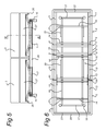
- the lower frame 1 consists of two lower longitudinal sections 16 and two lower transverse sections 17, as well as of feet 18 which are disposed at the corner points where the lower longitudinal sections and the lower transverse sections are attached to one another. Furthermore, fixed supports 19 are attached to the lower longitudinal sections 16 at the position of the traverse members 14.
- the traverse members 14 which are attached to the movable frame members 4-6, are all provided opposite the corresponding supports 19 on the lower frame with supporting rubbers 21 which rest on the supports 19, as shown in figure 1 by continuous lines.
- a soft edge trim 28 is attached to the outer side of the upper longitudinal sections 11-13 and 20 and of the upper traverse sections 22, 23.
- a spiral mattress supporting base which corresponds to that of figures 1 and 2 , but onto which the box spring mattress indicated by 25 is coupled in its entirety.
- This box spring mattress 25 consists of the lower mattress 27 and the circumferential element 26 attached to the circumference thereof, which covers the upper longitudinal sections 11-13 and 20 as well as the upper transverse sections 22 and 23 (the soft edge trim 28 is omitted here).
- the upper mattress 3 is placed on top of this box spring mattress 25.
- Figure 5 shows an embodiment wherein two adjacently arranged spiral mattress supporting bases according to the invention are coupled by means of coupling sections 29 which are attached to the transverse sections 17. In this embodiment only four feet 18 are present.
Landscapes
- Health & Medical Sciences (AREA)
- General Health & Medical Sciences (AREA)
- Nursing (AREA)
- Mattresses And Other Support Structures For Chairs And Beds (AREA)
- Invalid Beds And Related Equipment (AREA)
Applications Claiming Priority (1)
| Application Number | Priority Date | Filing Date | Title |
|---|---|---|---|
| NL2001550A NL2001550C2 (nl) | 2008-05-06 | 2008-05-06 | Verstelbare spiraalmatrasdrager met afknelbeveiliging. |
Publications (3)
| Publication Number | Publication Date |
|---|---|
| EP2116151A2 true EP2116151A2 (de) | 2009-11-11 |
| EP2116151A3 EP2116151A3 (de) | 2012-05-30 |
| EP2116151B1 EP2116151B1 (de) | 2015-09-30 |
Family
ID=40084385
Family Applications (1)
| Application Number | Title | Priority Date | Filing Date |
|---|---|---|---|
| EP09159560.3A Not-in-force EP2116151B1 (de) | 2008-05-06 | 2009-05-06 | Einstellbare Mattentrageunterlage mit Spiralbewehrung mit Verfangschutz |
Country Status (3)
| Country | Link |
|---|---|
| EP (1) | EP2116151B1 (de) |
| DK (1) | DK2116151T3 (de) |
| NL (1) | NL2001550C2 (de) |
Citations (2)
| Publication number | Priority date | Publication date | Assignee | Title |
|---|---|---|---|---|
| WO2007010234A1 (en) | 2005-07-20 | 2007-01-25 | Huntleigh Technology Limited | A hinge for bed frame assembly |
| WO2007010218A2 (en) | 2005-07-20 | 2007-01-25 | Huntleigh Technology Limited | Bed assembly |
Family Cites Families (8)
| Publication number | Priority date | Publication date | Assignee | Title |
|---|---|---|---|---|
| NL9200992A (nl) * | 1992-06-05 | 1994-01-03 | Kuperus Almelo B V | Draagbodem voor een matras. |
| US5537701A (en) * | 1994-03-15 | 1996-07-23 | Maxwell Products, Inc. | Adjustable articulated bed |
| DE19839166C1 (de) * | 1998-08-28 | 1999-12-30 | Roessle & Wanner Gmbh | Liegebett |
| US6499162B1 (en) * | 2000-10-04 | 2002-12-31 | Kuo-Heey Chang | Power-driven bed |
| JP3957597B2 (ja) * | 2002-09-04 | 2007-08-15 | 三洋電機株式会社 | 可動ベッド |
| CA2471005A1 (fr) * | 2004-06-23 | 2005-12-23 | Martin Boudreau | Lit inclinable grand public manuel ou electrique |
| GB2419523B (en) * | 2004-11-02 | 2009-09-30 | Sleepsafe Ltd | An arrangement for supporting a person or animal |
| US7293309B1 (en) * | 2006-09-13 | 2007-11-13 | Ruoey Lung Enterprise Corp. | Automatically operated bed |
-
2008
- 2008-05-06 NL NL2001550A patent/NL2001550C2/nl not_active IP Right Cessation
-
2009
- 2009-05-06 EP EP09159560.3A patent/EP2116151B1/de not_active Not-in-force
- 2009-05-06 DK DK09159560.3T patent/DK2116151T3/en active
Patent Citations (2)
| Publication number | Priority date | Publication date | Assignee | Title |
|---|---|---|---|---|
| WO2007010234A1 (en) | 2005-07-20 | 2007-01-25 | Huntleigh Technology Limited | A hinge for bed frame assembly |
| WO2007010218A2 (en) | 2005-07-20 | 2007-01-25 | Huntleigh Technology Limited | Bed assembly |
Also Published As
| Publication number | Publication date |
|---|---|
| DK2116151T3 (en) | 2016-01-11 |
| EP2116151B1 (de) | 2015-09-30 |
| EP2116151A3 (de) | 2012-05-30 |
| NL2001550C2 (nl) | 2009-11-12 |
Similar Documents
| Publication | Publication Date | Title |
|---|---|---|
| KR101962511B1 (ko) | 플렉시블 매트리스 지지대를 가진 접이식 침대 | |
| US8209801B2 (en) | Leg lift mechanism for electric bed or chair | |
| US9706848B2 (en) | Waist supporting device equipped electric apparatus for lying and/or sitting | |
| US8091159B2 (en) | Mechanism and mattress for sofabed | |
| US20140041121A1 (en) | Lumbar Folding Bed | |
| US20150305507A1 (en) | Piece of seating furniture and fitting therefor | |
| KR101825108B1 (ko) | 안전장치를 갖는 전동침대 | |
| US8201886B2 (en) | Lumbar support | |
| US10219624B2 (en) | Seating/reclining-furniture | |
| US10327560B2 (en) | Convertible sofa with articulated arm rests | |
| EP2116151A2 (de) | Einstellbare Mattentrageunterlage mit Spiralbewehrung mit Verfangschutz | |
| KR101090420B1 (ko) | 의자 일체형 테이블의 의자 자동 접철장치 | |
| US7762629B2 (en) | Seating or reclining furniture | |
| WO2007021179A1 (en) | Piece of furniture | |
| CN101919634B (zh) | 具有下陷保护装置的可调节弹簧床垫支撑基座 | |
| EP2380463B1 (de) | Anordnung für ein verstellbares Bett | |
| ITMI20090152A1 (it) | Poltrona materasso | |
| DE19618799A1 (de) | Sitz-Liege-Möbel mit mehreren Polsterteilen | |
| EP2208443A1 (de) | Verfahren zur Herstellung von einem Matratzenboden mit einem Träger | |
| EP2380462B1 (de) | Quetschschutzanordnung für ein verstellbares Bett | |
| EP1016360B1 (de) | Bett mit gegliederte Untermatratze | |
| KR200458497Y1 (ko) | 등받이 및 이를 구비한 의자 | |
| KR100743937B1 (ko) | 가변 등받이형 의자 | |
| EP1913919B1 (de) | Justierbare Bettunterlage und Bett mit justierbarer Kopfstütze | |
| AU2003200803A1 (en) | Spinal support device |
Legal Events
| Date | Code | Title | Description |
|---|---|---|---|
| PUAI | Public reference made under article 153(3) epc to a published international application that has entered the european phase |
Free format text: ORIGINAL CODE: 0009012 |
|
| AK | Designated contracting states |
Kind code of ref document: A2 Designated state(s): AT BE BG CH CY CZ DE DK EE ES FI FR GB GR HR HU IE IS IT LI LT LU LV MC MK MT NL NO PL PT RO SE SI SK TR |
|
| PUAL | Search report despatched |
Free format text: ORIGINAL CODE: 0009013 |
|
| AK | Designated contracting states |
Kind code of ref document: A3 Designated state(s): AT BE BG CH CY CZ DE DK EE ES FI FR GB GR HR HU IE IS IT LI LT LU LV MC MK MT NL NO PL PT RO SE SI SK TR |
|
| RIC1 | Information provided on ipc code assigned before grant |
Ipc: A47C 20/04 20060101AFI20120426BHEP Ipc: A47C 23/26 20060101ALI20120426BHEP Ipc: A47C 23/145 20060101ALI20120426BHEP Ipc: A47C 23/14 20060101ALI20120426BHEP |
|
| 17P | Request for examination filed |
Effective date: 20120815 |
|
| 17Q | First examination report despatched |
Effective date: 20131210 |
|
| GRAP | Despatch of communication of intention to grant a patent |
Free format text: ORIGINAL CODE: EPIDOSNIGR1 |
|
| 17Q | First examination report despatched |
Effective date: 20131210 |
|
| INTG | Intention to grant announced |
Effective date: 20140528 |
|
| GRAS | Grant fee paid |
Free format text: ORIGINAL CODE: EPIDOSNIGR3 |
|
| TPAC | Observations by third parties |
Free format text: ORIGINAL CODE: EPIDOSNTIPA |
|
| TPAC | Observations by third parties |
Free format text: ORIGINAL CODE: EPIDOSNTIPA |
|
| RAP1 | Party data changed (applicant data changed or rights of an application transferred) |
Owner name: KONINKLIJKE AUPING B.V. |
|
| RIN1 | Information on inventor provided before grant (corrected) |
Inventor name: KONINKLIJKE AUPING B.V. |
|
| RIN1 | Information on inventor provided before grant (corrected) |
Inventor name: DE LA HAYE, CORNELIS FRANCISCUS |
|
| GRAP | Despatch of communication of intention to grant a patent |
Free format text: ORIGINAL CODE: EPIDOSNIGR1 |
|
| INTG | Intention to grant announced |
Effective date: 20150720 |
|
| GRAA | (expected) grant |
Free format text: ORIGINAL CODE: 0009210 |
|
| AK | Designated contracting states |
Kind code of ref document: B1 Designated state(s): AT BE BG CH CY CZ DE DK EE ES FI FR GB GR HR HU IE IS IT LI LT LU LV MC MK MT NL NO PL PT RO SE SI SK TR |
|
| REG | Reference to a national code |
Ref country code: CH Ref legal event code: EP Ref country code: GB Ref legal event code: FG4D |
|
| REG | Reference to a national code |
Ref country code: AT Ref legal event code: REF Ref document number: 751863 Country of ref document: AT Kind code of ref document: T Effective date: 20151015 |
|
| REG | Reference to a national code |
Ref country code: IE Ref legal event code: FG4D |
|
| REG | Reference to a national code |
Ref country code: DE Ref legal event code: R096 Ref document number: 602009033890 Country of ref document: DE |
|
| REG | Reference to a national code |
Ref country code: DK Ref legal event code: T3 Effective date: 20160110 |
|
| REG | Reference to a national code |
Ref country code: SE Ref legal event code: TRGR |
|
| PG25 | Lapsed in a contracting state [announced via postgrant information from national office to epo] |
Ref country code: GR Free format text: LAPSE BECAUSE OF FAILURE TO SUBMIT A TRANSLATION OF THE DESCRIPTION OR TO PAY THE FEE WITHIN THE PRESCRIBED TIME-LIMIT Effective date: 20151231 Ref country code: LV Free format text: LAPSE BECAUSE OF FAILURE TO SUBMIT A TRANSLATION OF THE DESCRIPTION OR TO PAY THE FEE WITHIN THE PRESCRIBED TIME-LIMIT Effective date: 20150930 Ref country code: LT Free format text: LAPSE BECAUSE OF FAILURE TO SUBMIT A TRANSLATION OF THE DESCRIPTION OR TO PAY THE FEE WITHIN THE PRESCRIBED TIME-LIMIT Effective date: 20150930 |
|
| REG | Reference to a national code |
Ref country code: CH Ref legal event code: NV Representative=s name: FIAMMENGHI-FIAMMENGHI, CH |
|
| REG | Reference to a national code |
Ref country code: LT Ref legal event code: MG4D |
|
| REG | Reference to a national code |
Ref country code: NO Ref legal event code: T2 Effective date: 20150930 |
|
| PG25 | Lapsed in a contracting state [announced via postgrant information from national office to epo] |
Ref country code: HR Free format text: LAPSE BECAUSE OF FAILURE TO SUBMIT A TRANSLATION OF THE DESCRIPTION OR TO PAY THE FEE WITHIN THE PRESCRIBED TIME-LIMIT Effective date: 20150930 |
|
| REG | Reference to a national code |
Ref country code: NL Ref legal event code: FP |
|
| PG25 | Lapsed in a contracting state [announced via postgrant information from national office to epo] |
Ref country code: EE Free format text: LAPSE BECAUSE OF FAILURE TO SUBMIT A TRANSLATION OF THE DESCRIPTION OR TO PAY THE FEE WITHIN THE PRESCRIBED TIME-LIMIT Effective date: 20150930 Ref country code: ES Free format text: LAPSE BECAUSE OF FAILURE TO SUBMIT A TRANSLATION OF THE DESCRIPTION OR TO PAY THE FEE WITHIN THE PRESCRIBED TIME-LIMIT Effective date: 20150930 Ref country code: IS Free format text: LAPSE BECAUSE OF FAILURE TO SUBMIT A TRANSLATION OF THE DESCRIPTION OR TO PAY THE FEE WITHIN THE PRESCRIBED TIME-LIMIT Effective date: 20160130 Ref country code: CZ Free format text: LAPSE BECAUSE OF FAILURE TO SUBMIT A TRANSLATION OF THE DESCRIPTION OR TO PAY THE FEE WITHIN THE PRESCRIBED TIME-LIMIT Effective date: 20150930 Ref country code: SK Free format text: LAPSE BECAUSE OF FAILURE TO SUBMIT A TRANSLATION OF THE DESCRIPTION OR TO PAY THE FEE WITHIN THE PRESCRIBED TIME-LIMIT Effective date: 20150930 Ref country code: IT Free format text: LAPSE BECAUSE OF FAILURE TO SUBMIT A TRANSLATION OF THE DESCRIPTION OR TO PAY THE FEE WITHIN THE PRESCRIBED TIME-LIMIT Effective date: 20150930 |
|
| REG | Reference to a national code |
Ref country code: FR Ref legal event code: PLFP Year of fee payment: 8 |
|
| PG25 | Lapsed in a contracting state [announced via postgrant information from national office to epo] |
Ref country code: PL Free format text: LAPSE BECAUSE OF FAILURE TO SUBMIT A TRANSLATION OF THE DESCRIPTION OR TO PAY THE FEE WITHIN THE PRESCRIBED TIME-LIMIT Effective date: 20150930 Ref country code: RO Free format text: LAPSE BECAUSE OF FAILURE TO SUBMIT A TRANSLATION OF THE DESCRIPTION OR TO PAY THE FEE WITHIN THE PRESCRIBED TIME-LIMIT Effective date: 20150930 Ref country code: PT Free format text: LAPSE BECAUSE OF FAILURE TO SUBMIT A TRANSLATION OF THE DESCRIPTION OR TO PAY THE FEE WITHIN THE PRESCRIBED TIME-LIMIT Effective date: 20160201 |
|
| REG | Reference to a national code |
Ref country code: DE Ref legal event code: R097 Ref document number: 602009033890 Country of ref document: DE |
|
| PLBE | No opposition filed within time limit |
Free format text: ORIGINAL CODE: 0009261 |
|
| STAA | Information on the status of an ep patent application or granted ep patent |
Free format text: STATUS: NO OPPOSITION FILED WITHIN TIME LIMIT |
|
| 26N | No opposition filed |
Effective date: 20160701 |
|
| PG25 | Lapsed in a contracting state [announced via postgrant information from national office to epo] |
Ref country code: SI Free format text: LAPSE BECAUSE OF FAILURE TO SUBMIT A TRANSLATION OF THE DESCRIPTION OR TO PAY THE FEE WITHIN THE PRESCRIBED TIME-LIMIT Effective date: 20150930 |
|
| REG | Reference to a national code |
Ref country code: IE Ref legal event code: MM4A |
|
| REG | Reference to a national code |
Ref country code: FR Ref legal event code: PLFP Year of fee payment: 9 |
|
| PG25 | Lapsed in a contracting state [announced via postgrant information from national office to epo] |
Ref country code: IE Free format text: LAPSE BECAUSE OF NON-PAYMENT OF DUE FEES Effective date: 20160506 |
|
| PGFP | Annual fee paid to national office [announced via postgrant information from national office to epo] |
Ref country code: NL Payment date: 20170511 Year of fee payment: 9 |
|
| PGFP | Annual fee paid to national office [announced via postgrant information from national office to epo] |
Ref country code: GB Payment date: 20170530 Year of fee payment: 9 Ref country code: FR Payment date: 20170529 Year of fee payment: 9 Ref country code: CH Payment date: 20170529 Year of fee payment: 9 Ref country code: DK Payment date: 20170526 Year of fee payment: 9 Ref country code: NO Payment date: 20170523 Year of fee payment: 9 |
|
| PGFP | Annual fee paid to national office [announced via postgrant information from national office to epo] |
Ref country code: AT Payment date: 20170529 Year of fee payment: 9 Ref country code: FI Payment date: 20170523 Year of fee payment: 9 Ref country code: SE Payment date: 20170524 Year of fee payment: 9 Ref country code: BE Payment date: 20170529 Year of fee payment: 9 Ref country code: LU Payment date: 20170530 Year of fee payment: 9 |
|
| PGFP | Annual fee paid to national office [announced via postgrant information from national office to epo] |
Ref country code: DE Payment date: 20170731 Year of fee payment: 9 |
|
| PG25 | Lapsed in a contracting state [announced via postgrant information from national office to epo] |
Ref country code: HU Free format text: LAPSE BECAUSE OF FAILURE TO SUBMIT A TRANSLATION OF THE DESCRIPTION OR TO PAY THE FEE WITHIN THE PRESCRIBED TIME-LIMIT; INVALID AB INITIO Effective date: 20090506 Ref country code: CY Free format text: LAPSE BECAUSE OF FAILURE TO SUBMIT A TRANSLATION OF THE DESCRIPTION OR TO PAY THE FEE WITHIN THE PRESCRIBED TIME-LIMIT Effective date: 20150930 |
|
| PG25 | Lapsed in a contracting state [announced via postgrant information from national office to epo] |
Ref country code: MT Free format text: LAPSE BECAUSE OF NON-PAYMENT OF DUE FEES Effective date: 20160531 Ref country code: MC Free format text: LAPSE BECAUSE OF FAILURE TO SUBMIT A TRANSLATION OF THE DESCRIPTION OR TO PAY THE FEE WITHIN THE PRESCRIBED TIME-LIMIT Effective date: 20150930 Ref country code: MK Free format text: LAPSE BECAUSE OF FAILURE TO SUBMIT A TRANSLATION OF THE DESCRIPTION OR TO PAY THE FEE WITHIN THE PRESCRIBED TIME-LIMIT Effective date: 20150930 Ref country code: TR Free format text: LAPSE BECAUSE OF FAILURE TO SUBMIT A TRANSLATION OF THE DESCRIPTION OR TO PAY THE FEE WITHIN THE PRESCRIBED TIME-LIMIT Effective date: 20150930 |
|
| PG25 | Lapsed in a contracting state [announced via postgrant information from national office to epo] |
Ref country code: BG Free format text: LAPSE BECAUSE OF FAILURE TO SUBMIT A TRANSLATION OF THE DESCRIPTION OR TO PAY THE FEE WITHIN THE PRESCRIBED TIME-LIMIT Effective date: 20150930 |
|
| REG | Reference to a national code |
Ref country code: DE Ref legal event code: R119 Ref document number: 602009033890 Country of ref document: DE |
|
| REG | Reference to a national code |
Ref country code: CH Ref legal event code: PL |
|
| REG | Reference to a national code |
Ref country code: NO Ref legal event code: MMEP |
|
| REG | Reference to a national code |
Ref country code: DK Ref legal event code: EBP Effective date: 20180531 Ref country code: SE Ref legal event code: EUG Ref country code: NL Ref legal event code: MM Effective date: 20180601 |
|
| REG | Reference to a national code |
Ref country code: AT Ref legal event code: MM01 Ref document number: 751863 Country of ref document: AT Kind code of ref document: T Effective date: 20180506 |
|
| GBPC | Gb: european patent ceased through non-payment of renewal fee |
Effective date: 20180506 |
|
| REG | Reference to a national code |
Ref country code: BE Ref legal event code: FP Effective date: 20151228 Ref country code: BE Ref legal event code: MM Effective date: 20180531 |
|
| PG25 | Lapsed in a contracting state [announced via postgrant information from national office to epo] |
Ref country code: AT Free format text: LAPSE BECAUSE OF NON-PAYMENT OF DUE FEES Effective date: 20180506 Ref country code: SE Free format text: LAPSE BECAUSE OF NON-PAYMENT OF DUE FEES Effective date: 20180507 Ref country code: FI Free format text: LAPSE BECAUSE OF NON-PAYMENT OF DUE FEES Effective date: 20180506 Ref country code: NO Free format text: LAPSE BECAUSE OF NON-PAYMENT OF DUE FEES Effective date: 20180531 |
|
| PG25 | Lapsed in a contracting state [announced via postgrant information from national office to epo] |
Ref country code: CH Free format text: LAPSE BECAUSE OF NON-PAYMENT OF DUE FEES Effective date: 20180531 Ref country code: LI Free format text: LAPSE BECAUSE OF NON-PAYMENT OF DUE FEES Effective date: 20180531 |
|
| PG25 | Lapsed in a contracting state [announced via postgrant information from national office to epo] |
Ref country code: LU Free format text: LAPSE BECAUSE OF NON-PAYMENT OF DUE FEES Effective date: 20180506 |
|
| PG25 | Lapsed in a contracting state [announced via postgrant information from national office to epo] |
Ref country code: FR Free format text: LAPSE BECAUSE OF NON-PAYMENT OF DUE FEES Effective date: 20180531 Ref country code: DE Free format text: LAPSE BECAUSE OF NON-PAYMENT OF DUE FEES Effective date: 20181201 Ref country code: GB Free format text: LAPSE BECAUSE OF NON-PAYMENT OF DUE FEES Effective date: 20180506 Ref country code: NL Free format text: LAPSE BECAUSE OF NON-PAYMENT OF DUE FEES Effective date: 20180601 |
|
| PG25 | Lapsed in a contracting state [announced via postgrant information from national office to epo] |
Ref country code: DK Free format text: LAPSE BECAUSE OF NON-PAYMENT OF DUE FEES Effective date: 20180531 Ref country code: BE Free format text: LAPSE BECAUSE OF NON-PAYMENT OF DUE FEES Effective date: 20180531 |