EP2116281A1 - Méthode et dispositif pour la production de mousse pour l'extinction de feu - Google Patents
Méthode et dispositif pour la production de mousse pour l'extinction de feu Download PDFInfo
- Publication number
- EP2116281A1 EP2116281A1 EP09159446A EP09159446A EP2116281A1 EP 2116281 A1 EP2116281 A1 EP 2116281A1 EP 09159446 A EP09159446 A EP 09159446A EP 09159446 A EP09159446 A EP 09159446A EP 2116281 A1 EP2116281 A1 EP 2116281A1
- Authority
- EP
- European Patent Office
- Prior art keywords
- tank
- water
- foaming liquid
- fire
- line
- Prior art date
- Legal status (The legal status is an assumption and is not a legal conclusion. Google has not performed a legal analysis and makes no representation as to the accuracy of the status listed.)
- Withdrawn
Links
- 239000006260 foam Substances 0.000 title claims abstract description 44
- 238000000034 method Methods 0.000 title description 3
- XLYOFNOQVPJJNP-UHFFFAOYSA-N water Substances O XLYOFNOQVPJJNP-UHFFFAOYSA-N 0.000 claims abstract description 75
- 238000005187 foaming Methods 0.000 claims abstract description 69
- 239000007788 liquid Substances 0.000 claims abstract description 65
- 238000002156 mixing Methods 0.000 claims abstract description 30
- 238000004891 communication Methods 0.000 claims abstract description 6
- 239000000203 mixture Substances 0.000 claims description 12
- 238000004519 manufacturing process Methods 0.000 claims description 7
- 238000011144 upstream manufacturing Methods 0.000 claims description 5
- 239000004088 foaming agent Substances 0.000 description 13
- 239000012528 membrane Substances 0.000 description 5
- 239000002184 metal Substances 0.000 description 4
- 229910052751 metal Inorganic materials 0.000 description 4
- 239000000243 solution Substances 0.000 description 4
- 238000006073 displacement reaction Methods 0.000 description 3
- 239000000446 fuel Substances 0.000 description 3
- 238000012423 maintenance Methods 0.000 description 3
- RYGMFSIKBFXOCR-UHFFFAOYSA-N Copper Chemical compound [Cu] RYGMFSIKBFXOCR-UHFFFAOYSA-N 0.000 description 2
- 230000009471 action Effects 0.000 description 2
- 230000008901 benefit Effects 0.000 description 2
- 238000001816 cooling Methods 0.000 description 2
- 229910052802 copper Inorganic materials 0.000 description 2
- 239000010949 copper Substances 0.000 description 2
- 230000007797 corrosion Effects 0.000 description 2
- 238000005260 corrosion Methods 0.000 description 2
- 238000007599 discharging Methods 0.000 description 2
- 230000000694 effects Effects 0.000 description 2
- 239000000126 substance Substances 0.000 description 2
- 230000002159 abnormal effect Effects 0.000 description 1
- 150000001298 alcohols Chemical class 0.000 description 1
- 238000004458 analytical method Methods 0.000 description 1
- 230000008033 biological extinction Effects 0.000 description 1
- 230000008859 change Effects 0.000 description 1
- 230000002925 chemical effect Effects 0.000 description 1
- 239000003795 chemical substances by application Substances 0.000 description 1
- 238000002485 combustion reaction Methods 0.000 description 1
- 238000011109 contamination Methods 0.000 description 1
- 230000001419 dependent effect Effects 0.000 description 1
- 230000006866 deterioration Effects 0.000 description 1
- 238000010790 dilution Methods 0.000 description 1
- 239000012895 dilution Substances 0.000 description 1
- 239000004744 fabric Substances 0.000 description 1
- 229930195733 hydrocarbon Natural products 0.000 description 1
- 150000002430 hydrocarbons Chemical class 0.000 description 1
- 238000002347 injection Methods 0.000 description 1
- 239000007924 injection Substances 0.000 description 1
- 230000000737 periodic effect Effects 0.000 description 1
- 230000000704 physical effect Effects 0.000 description 1
- 230000008569 process Effects 0.000 description 1
- 230000009467 reduction Effects 0.000 description 1
- 239000011343 solid material Substances 0.000 description 1
- 239000007921 spray Substances 0.000 description 1
- 238000005507 spraying Methods 0.000 description 1
- 229910001220 stainless steel Inorganic materials 0.000 description 1
- 239000010935 stainless steel Substances 0.000 description 1
- 239000004094 surface-active agent Substances 0.000 description 1
Images



Classifications
-
- A—HUMAN NECESSITIES
- A62—LIFE-SAVING; FIRE-FIGHTING
- A62C—FIRE-FIGHTING
- A62C5/00—Making of fire-extinguishing materials immediately before use
- A62C5/02—Making of fire-extinguishing materials immediately before use of foam
-
- A—HUMAN NECESSITIES
- A62—LIFE-SAVING; FIRE-FIGHTING
- A62C—FIRE-FIGHTING
- A62C5/00—Making of fire-extinguishing materials immediately before use
- A62C5/002—Apparatus for mixing extinguishants with water
-
- B—PERFORMING OPERATIONS; TRANSPORTING
- B01—PHYSICAL OR CHEMICAL PROCESSES OR APPARATUS IN GENERAL
- B01F—MIXING, e.g. DISSOLVING, EMULSIFYING OR DISPERSING
- B01F23/00—Mixing according to the phases to be mixed, e.g. dispersing or emulsifying
- B01F23/20—Mixing gases with liquids
- B01F23/23—Mixing gases with liquids by introducing gases into liquid media, e.g. for producing aerated liquids
- B01F23/235—Mixing gases with liquids by introducing gases into liquid media, e.g. for producing aerated liquids for making foam
Definitions
- Fire-fighting foam finds use in fire-fighting systems designed for suppressing fires generated by combustion of hydrocarbons and solid materials.
- the extinguishing effect of foam is caused by a combination of chemical and physical effects, comprising a suffocating action (foam is lighter than water and fuels, and forms a continuous sheet separating fuel from air) and a cooling action (reduction of fuel temperature below the flash point, due to the high percentage of water contained therein).
- foaming liquids are known, which are formed of mixtures of surfactants, fluoroprotein foaming liquids, fluoro-synthetic foaming liquids and foaming liquids for alcohols. Based on the ratio of the volume of the foam being produced to the original water-foaming agent solution, the fire-fighting foams may be classified into high expansion foams (1:500 - 1:1000), medium expansion foams (1:30 - 1:200) and low expansion foams (1:6 - 1:12).
- the fire-fighting foam generating process includes two successive steps: first a foaming agent-water mixture or solution is formed and then the mixture so obtained is foamed with air to obtain agglomerated bubbles.
- the foaming liquid is typically stored in a refillable tank, with water being fed to the system from a water supply.
- the foaming liquid and water may be mixed together in the following manner:
- Liquid displacement mixers are a variant of suction mixers. These devices include a pressure tank with a bladder (or membrane) of rubberized fabric therein containing the foaming agent, and an external premixer.
- the membrane prevents the foaming agent in the tank from contacting water and the container wall, thereby avoiding dilution, as well as any contamination of the foaming agent and tank corrosion.
- the premixer is a Venturi tube fitted into the fire extinguishing water pipe that supplies the system.
- a pipe extends upstream from the nozzle of the Venturi tube, and connects the stub pipe to the water part of the tanks, i.e. the space between the tank walls and the bladder.
- a pipe also extends from the stub pipe, downstream from the nozzle, before the choke, for connection to the plunger tube at the tip of the tank in the foaming agent part.
- the space between the tank walls and the bladder is occupied by pressurized water.
- the water and the foaming agent are at the same pressure, whereas when the system is operating, the foaming agent is at a lower pressure. Therefore, water enters the tank, presses onto the bladder wall and displaces the foaming agent, which is ejected from the top and sucked in by the Venturi tube, where it is mixed with water.
- the percentage of foaming liquid to be mixed with water is controlled by a diaphragm with a calibrated hole which is fitted into the pipe upstream from the mixer.
- the foaming liquid-water mixture is foamed with air using devices that utilize the Venturi effect (the latter solution being particularly used for foaming liquids having a low or medium expansion ratio) or by forced injection of air (for high expansion foams).
- a common solution for generating foam consists in causing the water - foaming agent mixture to be fed by pipes that end with a Venturi meter that creates the negative pressure required for taking in the air that is used to form the foam.
- the water to foaming liquid mixing ratio should fall within a given range.
- An insufficient amount of water causes increased viscosity of the foam being produced.
- an excess of water causes a deterioration of the extinguishing features of the foam.
- the object of this invention is to obviate at least some of prior art problems and particularly those set out hereinbefore.
- the valve 2 includes a pressurized water feeding line 1, which typically feeds water at a pressure from 3 to 8 bar, and at least one system operating valve 2 for controlling a water flow from the pressurized water feeding line.
- the valve 2 may be a heat-sensitive valve.
- a manually openable valve (not shown) may be mounted parallel to the heat sensitive valve 2.
- the valve 2 only includes a manual valve.
- a water motor alarm 9 may be provided in series with the valve 2 for triggering an audible alarm.
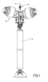
- a preferably vertically extending tank 3 is provided, which is adapted to operate at a pressure corresponding to the pressure of water from the water feeding line 1.
- Foaming liquid 4 is contained in the tank 3.
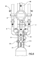
- the tank 3 has an upper water inflow line 31, which receives pressurized water from the feed line 1, and a lower outflow line 32, from which the foaming liquid 4 contained in the tank 3 is delivered.
- Two devices 5 are provided for mixing the water that comes directly from the feed line 1 and the foaming liquid that comes from the pressurized tank 3 through the outflow line 32, to create a flow of water - foaming liquid mixture.
- the mixing devices 5 are simple T-joints and the foaming liquid, that has a higher pressure than water, is fed thereto through lateral line 51 receiving the liquid from the outflow line 32 (see Figure 6 ).
- a normally open manual valve (not shown) may be provided on each lateral foaming liquid feeding line 51, and may be closed for maintenance purposes.
- a foam generating device 6 which receives the foaming liquid-water flow is provided downstream from each mixing device 5.
- a manually or automatically operating valve e.g. a heat-sensitive valve
- a heat-sensitive valve may be provided between each mixing device (5) and the foam generating device (6).
- Two mixing devices 5 are provided in the illustrated embodiment.
- a cross 100 is provided, which distributes the water that comes from the feed line 1 into two main flows, directed to the two mixing devices 5, 5 and a secondary flow, directed to the inflow line 31 of the tank 3.
- the foaming liquid that comes out of the tank 3 through the outflow line 32 branches into two flows directed to the two mixing devices 5, 5.
- the outflow line 32 may be connected with the mixing devices 5, 5, using flexible metal hoses 51, e.g. made of copper.
- the use of copper hoses facilitates hydraulic connections.
- the tank 3 may be made of metal, such as stainless steel. This characteristic imparts corrosion resistance and allows the system to be directly placed in the area potentially exposed to fires, which eventually allows the hoses connecting the mixing devices 5 and the foam generating devices 6 to have a smaller length. By placing the tank 3 in the potential fire-fighting area, fire-fighting times are also reduced, and lower pressure losses occur between the water distribution system and the foam generators.
- the system is composed of fixed pipes and the foam generating devices 6 may be conventional high expansion foam generators of the suction type, which include a number of nozzles 61 for spraying the foaming liquid-water mixture into a generally frustoconical element formed of a metal mesh, such as a perforated mesh or an expanded mesh.
- Foam generators may also be of the high, medium or low expansion type, as needed.
- at least one of the foam generating devices may be a conventional low or medium expansion spray nozzle connected to the system by hoses.
- the tank 3 is fed at its top with water from the inflow line 31.
- the outflow line 31, at the bottom end of the tank 3, delivers the foaming liquid contained in the tank 3.
- the inflow line 31 and outflow line 32 of the tank 3 are in hydraulic communication within the tank.
- the tank 3 has an internal chamber in which water that comes from the inflow line 31 is in direct contact with the top level of the column of foaming liquid 4 and directly presses onto the column of foaming liquid, like a piston, thereby causing the foaming liquid to come out of the bottom end of the tank 3 through the outflow line 32.
- the tank 3 involves lower costs and has a smaller size than traditional membrane tanks. Unlike the prior art, the lack of a membrane in the tank 3 allows proper operation of the tank 3 also at high temperatures, and hence even during fire extinction.
- the tank 3 has a vertical extension. This feature reduces the risk that the water coming from the inflow line 31 and the foaming agent 4 in the tank 3 may mix together.
- the tank 3 has a substantially and/or generally cylindrical shape, and the ratio of the height h to the diameter ⁇ of the tank 3 is 5 or above.
- a jet breaker 33 may be provided in the upper part within the tank 3, under the inlet of the inflow line 31, for deflecting water from the inflow line 31. This feature further reduces the risk that the water coming into the tank 3 and the foaming agent 4 in the tank 3 may undesirably mix together.
- the outflow line 32 draws the foaming liquid through a tube 321 projecting out of the bottom of the tank 3. This feature may prevent the risk that any deposits on the bottom of the tank 3 may obstruct the outlet 32 of the tank.
- the mixing device 5 is placed at a height above the tank 3, i.e. at a height above the maximum height of the foaming liquid contained in the pressurized tank 3. This feature allows the mixing device 5 to be free of foaming liquid when the fire-fighting system is not operating.
- a flow reducing member such as a calibrated hole (not shown) is provided upstream from each mixing device 5, and is designed to keep the flow rate of the foaming liquid substantially constant in spite of any water pressure change, and hence to ensure a consistent ratio of the foaming liquid introduced into the mixing device 5 to water (typically the water/foaming liquid mixture contains 3-6% v/v foaming liquid).
- These calibrated orifices also assist in creating a pressure difference between the water that flows into the mixing device 5 and the foaming liquid introduced from the sides, thereby facilitating the inflow of foaming liquid.
- the calibrated orifices are located in the proximity of the outflow line 32.
- a second cross 110 is provided between the cross 10 and the inflow line 31.
- a relief valve 35 for the tank 3 and a pressure gage are connected to the second cross 110.
- the relief valve 35 is normally closed and is only opened during maintenance of the system (such as when loading the foaming liquid).
- a normally open feeding valve 37 may be provided between the second cross 110 and the inflow line 31, and is closed during maintenance (removal of the tank 3). Otherwise, the feeding valve 37 may be situated between the first cross 10 and the second cross 110.
- a non-return valve may be placed between the cross 10 and each mixing device 5, for independent operation of each foam generator 6.
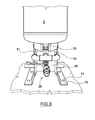
- a filling/discharging valve 36 is provided under the tank 3, for filling or discharging the tank 3.
- the discharge valve 36 is hydraulically connected to the outflow line 32.
- the discharge valve 36 is in communication with the tank 3 independently of the outflow line 32.
- a cooling nozzle 7 is provided, which is supplied with water by the feed line 1, and is in such position as to direct a water jet onto the top of the tank 3.
- the system disclosed hereinabove has the advantage that it has no mechanical moving parts or electrical devices, and it requires no pressurized gas tank.
- the fire-fighting system further comprises means 38, 39 for controlling the level of the foaming liquid 4 in the tank 3.
- the means for controlling the level of the foaming liquid 4 in the tank 3 include a lateral discharge pipe 38 and a manual valve 38.
- the lateral pipe 38 is situated at a height that is about 3 ⁇ 4 of the maximum height of the tank 3.
- the valve 39 may be also used for periodic checks (such as chemical analyses) of the foaming liquid 4 contained in the tank 3.
- This system lies on a structure that includes a pair of metal sections 70 (such as L-sections) integral with the tank 3.
- the L-sections have holes 71 for receiving fastener means, such as screw fasteners.
- the system is also secured to a vertical section 80, e.g. a U-section, with holes for wall-mounting.
- the above disclosed system may be used for implementing a method for producing fire-fighting foam, comprising the steps of
Landscapes
- Health & Medical Sciences (AREA)
- Public Health (AREA)
- Business, Economics & Management (AREA)
- Emergency Management (AREA)
- Chemical & Material Sciences (AREA)
- Chemical Kinetics & Catalysis (AREA)
- Fire-Extinguishing By Fire Departments, And Fire-Extinguishing Equipment And Control Thereof (AREA)
- Compounds Of Unknown Constitution (AREA)
Applications Claiming Priority (1)
| Application Number | Priority Date | Filing Date | Title |
|---|---|---|---|
| IT000827A ITMI20080827A1 (it) | 2008-05-08 | 2008-05-08 | Metodo ed impianto per produrre schiuma |
Publications (1)
| Publication Number | Publication Date |
|---|---|
| EP2116281A1 true EP2116281A1 (fr) | 2009-11-11 |
Family
ID=40302703
Family Applications (1)
| Application Number | Title | Priority Date | Filing Date |
|---|---|---|---|
| EP09159446A Withdrawn EP2116281A1 (fr) | 2008-05-08 | 2009-05-05 | Méthode et dispositif pour la production de mousse pour l'extinction de feu |
Country Status (2)
| Country | Link |
|---|---|
| EP (1) | EP2116281A1 (fr) |
| IT (1) | ITMI20080827A1 (fr) |
Cited By (1)
| Publication number | Priority date | Publication date | Assignee | Title |
|---|---|---|---|---|
| ITMI20091904A1 (it) * | 2009-11-02 | 2010-02-01 | Marco Mantovani | Metodo ed impianto per produrre schiuma antincendio |
Citations (3)
| Publication number | Priority date | Publication date | Assignee | Title |
|---|---|---|---|---|
| US2811211A (en) * | 1952-02-13 | 1957-10-29 | Pumpindustri Ab | Method and means for storing foam liquid in fire extinguishers |
| US5085278A (en) * | 1990-10-15 | 1992-02-04 | T. D. F. Partnership | Foam proportioning inductor apparatus |
| WO2001085318A2 (fr) * | 2000-05-12 | 2001-11-15 | John Bureaux | Procede et dispositif de production de mousse |
-
2008
- 2008-05-08 IT IT000827A patent/ITMI20080827A1/it unknown
-
2009
- 2009-05-05 EP EP09159446A patent/EP2116281A1/fr not_active Withdrawn
Patent Citations (3)
| Publication number | Priority date | Publication date | Assignee | Title |
|---|---|---|---|---|
| US2811211A (en) * | 1952-02-13 | 1957-10-29 | Pumpindustri Ab | Method and means for storing foam liquid in fire extinguishers |
| US5085278A (en) * | 1990-10-15 | 1992-02-04 | T. D. F. Partnership | Foam proportioning inductor apparatus |
| WO2001085318A2 (fr) * | 2000-05-12 | 2001-11-15 | John Bureaux | Procede et dispositif de production de mousse |
Cited By (1)
| Publication number | Priority date | Publication date | Assignee | Title |
|---|---|---|---|---|
| ITMI20091904A1 (it) * | 2009-11-02 | 2010-02-01 | Marco Mantovani | Metodo ed impianto per produrre schiuma antincendio |
Also Published As
| Publication number | Publication date |
|---|---|
| ITMI20080827A1 (it) | 2008-08-07 |
Similar Documents
| Publication | Publication Date | Title |
|---|---|---|
| KR0173996B1 (ko) | 기액용해 혼합방법 및 장치 | |
| TWI458515B (zh) | 高膨脹泡沫滅火設備 | |
| CN115427115B (zh) | 用于产生消防目的的气液混合物的设备 | |
| US20100116512A1 (en) | Fire suppression apparatus and method for generating foam | |
| US4318443A (en) | Foam generating fire fighting device | |
| JP4049284B2 (ja) | ウォーターミスト消火設備 | |
| WO1998018543A1 (fr) | Procede et appareil pour dissoudre/melanger un gaz dans un liquide | |
| EP4582149A1 (fr) | Appareil, système et procédé de moussage de mousse de lutte contre l'incendie | |
| US20170259091A1 (en) | Fire-fighting system | |
| US2577451A (en) | Apparatus for the production of air foam and air foam fire-extinguishing installations | |
| EP1075316B1 (fr) | Procede et appareil haute capacite pour la production de mousse extinctrice et dispositif epandeur de mousse a expansion | |
| JP2003245533A (ja) | 超微細気泡発生装置 | |
| CN110448828A (zh) | 正压式三相泡沫发生装置及方法和应用 | |
| JPH10244138A (ja) | 気液溶解混合方法と装置 | |
| KR101402520B1 (ko) | 포소화액 혼합분사장치 | |
| CN101190364A (zh) | 高膨胀泡沫灭火设备 | |
| US8109341B1 (en) | Method and high-capacity apparatus for producing fire fighting foam and foam expanding spreading device | |
| WO2007001212A2 (fr) | Melangeur et appareil d'extinction des incendies | |
| HK40082414B (en) | Device for producing a gas-liquid mixture for firefighting purposes | |
| CN114082389A (zh) | 一种多用途灭火剂及其生产设备 | |
| KR101884834B1 (ko) | 분말소화장치 | |
| US1467377A (en) | Foam-producing fire-extinguishing apparatus | |
| JP4066130B2 (ja) | 泡消火設備 | |
| HK40082414A (en) | Device for producing a gas-liquid mixture for firefighting purposes | |
| SU47174A1 (ru) | Устройство дл получени огнетушащей масл ной пены |
Legal Events
| Date | Code | Title | Description |
|---|---|---|---|
| PUAI | Public reference made under article 153(3) epc to a published international application that has entered the european phase |
Free format text: ORIGINAL CODE: 0009012 |
|
| AK | Designated contracting states |
Kind code of ref document: A1 Designated state(s): AT BE BG CH CY CZ DE DK EE ES FI FR GB GR HR HU IE IS IT LI LT LU LV MC MK MT NL NO PL PT RO SE SI SK TR |
|
| 17P | Request for examination filed |
Effective date: 20100420 |
|
| 17Q | First examination report despatched |
Effective date: 20170309 |
|
| STAA | Information on the status of an ep patent application or granted ep patent |
Free format text: STATUS: THE APPLICATION IS DEEMED TO BE WITHDRAWN |
|
| 18D | Application deemed to be withdrawn |
Effective date: 20181201 |