EP4582149A1 - Appareil, système et procédé de moussage de mousse de lutte contre l'incendie - Google Patents
Appareil, système et procédé de moussage de mousse de lutte contre l'incendie Download PDFInfo
- Publication number
- EP4582149A1 EP4582149A1 EP22957068.4A EP22957068A EP4582149A1 EP 4582149 A1 EP4582149 A1 EP 4582149A1 EP 22957068 A EP22957068 A EP 22957068A EP 4582149 A1 EP4582149 A1 EP 4582149A1
- Authority
- EP
- European Patent Office
- Prior art keywords
- foam
- flow path
- firefighting
- air
- tube
- Prior art date
- Legal status (The legal status is an assumption and is not a legal conclusion. Google has not performed a legal analysis and makes no representation as to the accuracy of the status listed.)
- Pending
Links
Images


Classifications
-
- A—HUMAN NECESSITIES
- A62—LIFE-SAVING; FIRE-FIGHTING
- A62C—FIRE-FIGHTING
- A62C5/00—Making of fire-extinguishing materials immediately before use
- A62C5/02—Making of fire-extinguishing materials immediately before use of foam
-
- A—HUMAN NECESSITIES
- A62—LIFE-SAVING; FIRE-FIGHTING
- A62C—FIRE-FIGHTING
- A62C31/00—Delivery of fire-extinguishing material
- A62C31/02—Nozzles specially adapted for fire-extinguishing
- A62C31/12—Nozzles specially adapted for fire-extinguishing for delivering foam or atomised foam
-
- A—HUMAN NECESSITIES
- A62—LIFE-SAVING; FIRE-FIGHTING
- A62C—FIRE-FIGHTING
- A62C37/00—Control of fire-fighting equipment
-
- A—HUMAN NECESSITIES
- A62—LIFE-SAVING; FIRE-FIGHTING
- A62C—FIRE-FIGHTING
- A62C5/00—Making of fire-extinguishing materials immediately before use
- A62C5/02—Making of fire-extinguishing materials immediately before use of foam
- A62C5/022—Making of fire-extinguishing materials immediately before use of foam with air or gas present as such
- A62C5/024—Apparatus in the form of pipes
-
- Y—GENERAL TAGGING OF NEW TECHNOLOGICAL DEVELOPMENTS; GENERAL TAGGING OF CROSS-SECTIONAL TECHNOLOGIES SPANNING OVER SEVERAL SECTIONS OF THE IPC; TECHNICAL SUBJECTS COVERED BY FORMER USPC CROSS-REFERENCE ART COLLECTIONS [XRACs] AND DIGESTS
- Y02—TECHNOLOGIES OR APPLICATIONS FOR MITIGATION OR ADAPTATION AGAINST CLIMATE CHANGE
- Y02E—REDUCTION OF GREENHOUSE GAS [GHG] EMISSIONS, RELATED TO ENERGY GENERATION, TRANSMISSION OR DISTRIBUTION
- Y02E60/00—Enabling technologies; Technologies with a potential or indirect contribution to GHG emissions mitigation
- Y02E60/10—Energy storage using batteries
Definitions
- the V F2 is between 6 and 12 m/s.
- the superficial velocity V 1I of the foam mixture injected at the inlet of the foam mixing chamber of the firefighting foam foaming device is between 2 m/s and 5 m/s;
- the firefighting foam foaming device comprises a two-phase flow injection seat, a jet nozzle assembly, and a foam mixing chamber.
- the two-phase flow injection seat enables water and foam stock to be injected into the foam mixing chamber along the first flow path to form a foam mixture column.
- the jet nozzle assembly enables the compressed air in the second flow path to fully interact with the foam mixture at different positions of the foam mixture column, so as to increase the contact area between the compressed air and the foam mixture column and improve the foaming effect.
- a single static mixer is connected to the pipeline or multiple static mixers are connected in series/parallel to form a set and connected to the pipeline.
- These devices feature a simple structure and reliable performance, and do not require additional driving force.
- These static mixers are divided into two categories in accordance with principle. One category starts from designing different fluid mixing and injection structures. For example: 1. dividing either the air phase flow or the liquid phase flow into several finer streams and injecting them into the outer interface of the other phase flow for mixing. 2.
- the other category starts from designing different spoiler structures, such as superimposed mesh plates, spiral flow guiding plates, three-dimensional grid plates, conical spoilers, etc. These designs ultimately aim to better disperse the air phase flow by the liquid phase flow, and to mix the two phase flows more evenly under the impact of spoiler, becoming a bubble flow with fine particles and uniform foam distribution.
- some other designs incorporate variable-diameter configurations like Venturi tubes or de Laval tubes in the upstream and downstream pipelines connecting the static mixers. This further enhances the impact and mixing effect of the two phase flows.
- the mechanism of generating foam by a compressed air foam system is to evenly mix the foam stock with water in a certain proportion first, and then mix the foam mixture with the compressed air to foam, i.e. inject the compressed air in a certain proportion into the foam mixture, and generate foam after the two phase flows were impacted and mixed.
- the stability, foaming property and fire extinguishing performance of the firefighting foam formed by the injection of compressed air are closely related to the physical properties of the foam stock, water and air, as well as the chemical composition of the foam stock.
- the main factors affecting the above-mentioned properties are the proportion of the foam mixture, air-liquid ratio, mixing pressure, surface contact area of the air-liquid two phases and the mixing uniformity of the two phases.
- the generation of compressed air foam is essentially a process of mixing and transporting air-liquid two-phase flow.
- this air-liquid two-phase flow forms five flow patterns: annular flow, slug flow, liquid-throttling flow, bubble flow and mist flow.
- the main flow pattern is bubble flow
- the formed foam has the best quality, with small average bubble size and a large number of bubbles, and the bubbles are evenly dispersed in the continuous liquid phase.
- the foam mixing device structures originally suitable for compressed air foam systems with a flow rate of ⁇ 100 L/s are difficult to provide sufficient contact area and means for the full mixing and foaming of the air-liquid two-phase flow.
- New problems arise during use such as: 1. the original uniformly-mixed bubble flow cannot be achieved, and foam quality becomes poor; 2. overcurrent pressure loss of the foam mixing device is excessive; 3. the device occupies a large space, making it difficult to be placed on a vehicle; 4. complex structure and poor reliability, etc.
- the firefighting foam foaming device for a large-flow compressed air foam system, which meets the successful application in vehicle-mounted or fixed system and achieves better fire extinguishing performance.
- the firefighting foam foaming device has achieved remarkable results in three aspects: firstly, it enables more uniform and delicate foam in mixing the large-flow two-phase flow; secondly, it reduces pipeline pressure loss, enabling the compressed air foam to achieve a longer spraying distance; thirdly, it features a simple and reliable structure with a small space occupation.
- Firefighting foam refers to a group of bubbles for firefighting with a small volume and surface surrounded by a liquid film. Due to its specific gravity being much smaller than that of common combustible liquids, it floats on the surface of the liquid, forming a foam covering layer. At the same time, firefighting foam has a certain viscosity and adheres to the surface of common combustible solids.
- the firefighting foam foaming method is as follows: Firstly, uniformly mixing the foam stock with water in a certain proportion, and then mixing the foam mixture with air for foaming, finally forming a fire extinguishing agent with fire extinguishing efficiency: firefighting foam.
- Foam stock a concentrated liquid that can be mixed with water at a suitable mixing ratio to form a foam solution.
- Foam mixture a foam solution prepared by mixing foam liquid with water at a specific mixing ratio.
- Foaming ratio the ratio of the foam volume to the volume of the foam mixture that forms the foam.
- Low-foaming-ratio foam firefighting foam with a foaming ratio of less than 20.
- Wet foam foam with a foaming ratio of less than 10.
- Dry foam foam with a foaming ratio of not less than 10.
- Compressed air foam fire truck a fire truck mainly equipped with a water tank and a foam liquid tank, which sprays foam for fire extinguishing through a compressed air foam system.
- Foam proportional mixing system a system consisting of components such as a foam ratio mixer, a foam stock pump, a controller and a pipeline device, which can mix water and foam stock at a certain ratio.
- Compressed air foam system a device that mainly consists of a firefighting pump, a compressed air system, a foam proportional mixing system, a spraying device, a pipeline system, etc. and can produce compressed air foam.
- d1 is the diameter of both ends of the main body 701.
- L4 is the thickness of the baffle 702.
- L6 is the width of the other end of the baffle 124''.
- ⁇ is the cone angle of the baffle 702.
- the liquid inlet hole 121 is in fluid communication with the first flow path 111 and the liquid inlet hole 121 is located downstream of the first flow path 111.
- the air inlet hole 122 is in fluid communication with the second flow path 112 and located downstream of the second flow path 112.
- the foam mixing chamber 130 is located downstream of the first flow path 111 and the second flow path 112 and in fluid communication with both the first flow path 111 and the second flow path 112; the first air outlet hole 123 and the second air outlet hole 124' both extend into the foam mixing chamber 130; the first air outlet hole 123 and the second air outlet hole 124' are located in different positions in the radial direction of the foam mixing chamber 130.
- Foam mixture is a mixture of foam stock and water.
- the foam mixture therein flows from the first inlet tube 140 into the first flow path 111 of the two-phase flow injection seat 110, wherein the fluid entered into the first flow path 111 flows along the line arrow S1, see Fig. 2 .
- the compressed air flows from the external line of the firefighting foam foaming device 100 along the second flow path 112 into the two-phase flow injection seat 110, wherein the fluid entered into the second flow path 112 flows along the dashed line arrow S2, see Fig. 2 .
- the compressed air flows from the external line into the second flow path 112 of the two-phase flow injection seat 110 and then flows along the air inlet hole 122 of the jet nozzle assembly 120 into the jet nozzle assembly 120.
- the compressed air entered into the jet nozzle assembly 120 is divided into two streams.
- One of the streams flows out of the jet nozzle assembly 120 from the first air outlet hole 123, namely the air stream S21; and the other stream flows out of the jet nozzle assembly 120 from the second air outlet hole 124', namely the air stream S22.
- the diameter of the first air outlet hole 123 has a diameter D5
- the second air outlet hole 124' has a diameter of D6.
- the first flow path 111 is located on the central axis of the two-phase flow injection seat 110; in particular, the first flow path 111 is an air inlet hole 122 extending through the two-phase flow injection seat 110 in the direction of its own axis.
- the second flow path 112 includes two sections.
- the first section branch is an air hole extending in the radial direction of the two-phase flow injection seat 110, and the second section branch is an annular groove, the axis of which extends parallel to the axial direction of the two-phase flow injection seat 110, and which is in fluid communication with the air hole of the first section branch.
- the external compressed air enters the first section branch first and then flows to the second section branch.
- the second flow path 112 is located on the outer side of the first flow path 111.
- Such a structure of the two-phase flow injection seat 110 not only enables the first flow path 111 and the second flow path 112 to be independent of each other, i.e. without crossflow or communication with each other, but also enables them to have a certain overlapping area in the axial direction of the two-phase flow injection seat 110. This effectively utilizes the space dimension of the two-phase flow injection seat 110, which occupies a small-volume structure and thus has a compact and reasonable structure.
- the jet nozzle assembly 120 is fixedly connected to the two-phase flow injection seat 110.
- the air inlet hole 122 of the jet nozzle assembly 120 is located downstream of the second flow path 122 of the two-phase flow injection seat 110.
- the compressed air entered into the jet nozzle assembly 120 is split and sprayed through the first air outlet hole 123 and the second air outlet hole 124'. Seen in the radial direction of the foam mixing chamber 130, the first air outlet hole 123 and the second air outlet hole 124' are located in different positions in the radial direction of the foam mixing chamber 130. The first air outlet hole 123 is closer to the radial edge of the foam mixing chamber 130 and the second air outlet hole 124' is closer to the central axis of the foam mixing chamber 130.
- the jet nozzle assembly 120 ingeniously enables the compressed air to be fully mixed with the foam mixture column from both the outer surface and the interior, expanding the contact area between the compressed air, foam, and water. Moreover, both the first air outlet hole 123 and the second air outlet hole 124' are located inside the foam mixing chamber 130, effectively reducing the overflow pressure loss caused by the space occupied by the jet nozzle assembly 120.
- the jet nozzle assembly 120 comprises a mounting plate 125, an axial tube 126 and a radial tube 127.
- the mounting plate 125 is in particular a flat plate. Its thickness should be dimensioned to meet the requirements of the fixed assembling and as thin as possible to make the structure of the entire firefighting foam foaming device 100 more compact and delicate.
- the mounting plate 125 is abutted against and secured to the two-phase flow injection seat 110, in particular by such as screw fixation, welding or riveting, etc.
- the mounting plate 125 is provided with the air inlet hole 122 in fluid communication with the second flow path 112 of the two-phase flow injection seat 110 and a liquid inlet hole 121 in fluid communication with the first flow path 111.
- the axial tube 126 is located on the side of the mounting plate 125 away from the two-phase flow injection seat 110, and the axial tube 126 and the mounting plate 125 are fixed by welding.
- the axis of the radial tube 127 is vertical to the central axis of the two-phase flow injection seat 110.
- the axial tube 126 is in fluid communication with the air inlet hole 122 of the mounting plate 125. The compressed air enters into the axial tube 126 along the air inlet hole 122 of the mounting plate 125.
- the central axis of the radial tube 127 intersects the central axis of the axial tube 126, and one end of the radial tube 127 is in fluid communication with the axial tube 126, in particular, the radial tube 127 is located at the part of the axial tube 126 near the downstream end.
- This structure allows the radial tube 127 to be at a certain axial distance from the inlet of the foam mixing chamber 130, so that the foam mixture interacts with the compressed air output from the radial tube 127 in a relatively stable state.
- the other end of the radial tube 127 away from the axial tube 126 is located on the side of the axial tube 126 facing the central axis of the two-phase flow injection seat 110.
- the compressed air output from the axial tube 126 interacts with the part of the liquid column formed by the foam mixture in the circumferential surface area
- the compressed air output from the radial tube 127 can extend in the central position of the foam mixture to interact with the part of the liquid column formed by the foam mixture in the central area, thereby greatly increasing the contact area of the compressed air with the foam mixture and enhancing the foaming effect.
- the arrangement of the axial tube 126 and the radial tube 127 reduces the resistance of the liquid flow shock.
- the other end of the radial tube 127 is away from the axial tube 126 and is closed; the side wall of the radial tube 127 near the other end of the axial tube 126 is provided with the second air outlet hole 124'; and the axial direction of the second air outlet hole 124' is parallel to the central axis of the two-phase flow injection seat 110 or, the axial direction of the second air outlet hole 124' is intersected by the central axis of the two-phase flow injection seat 110 with an angle of less than 90°.
- the other end of the axial tube 126 is away from the two-phase flow injection seat 110 and is open, and this opening is used as first air outlet hole 123.
- the other end of the axial tube 126 faces the inner wall of the foam mixing chamber 130, i.e. the conical inner wall of the foam mixing chamber 130.
- axial tubes 126 there is a plurality of axial tubes 126, such as 8 to 10.
- the plurality of axial tubes 126 are distributed in the circumferential direction of the mounting plate 125, in particular, they can be uniformly arranged. This arrangement enables the compressed air output from the axial tube 126 to interact with the liquid column formed by the foam mixture in multiple positions in the circumferential surface area, so as to enhance the foaming effect.
- each axial tube 126 is provided with a first air outlet hole 123.
- Each radial tube 127 is provided with a plurality of second outlet holes 124'.
- the first air outlet hole 123 has a large flow-through area and the individual second air outlet holes 124' are microporous.
- the flow-through area of the other end of the axial tube 126 is 1.5 to 2 times that of all the second air outlet holes 124' of the radial tubes 127 that are in fluid communication with the axial tube 126.
- the axial distance H1 see Fig.
- the interior of the foam mixing chamber 130 is configured as conical-cylindrical hole with the variable cross-section.
- the flowthrough diameter D3 of the foam outflow conical mouth is the same as the inflow flowthrough diameter D1 of the foam mixture of the two-phase flow injection seat 110, and the flowthrough diameter D2 of the cylindrical mouth of the foam mixing chamber 130 is 1.5 times the flowthrough diameter D3 of the conical mouth. That is, the inlet diameter D2 of the foam mixing chamber is 1.3 to 1.7 times the outlet diameter D3 of the foam mixing chamber 130, in particular such as 1.5 times. Using the afore proportional parameters, the foaming effect is effectively improved.
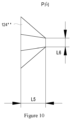
- the flow guiding plate 124'' is trapezoidal, i.e. it is relatively thick at one end connected to the axial tube 126 and is relatively thin at the other end.
- L5 is in the range of 15 to 30 mm and L6 is in the range of 5 to 8 mm.
- the flow guiding plate 124" has a conical angle ⁇ of 5° to 25°, in particular such as 15°, 18°, 20°, 22°, or 25°, etc.
- the afore technical solution ingeniously utilizes the low pressure region A formed on the backside of the jet nozzle assembly 120 after it is flowed through by the liquid stream to guide the compressed air, and after reflected from the inner conical surface of the foam mixing chamber 130, the compressed air enters into the middle part of the foam mixing chamber 130 along the backside of the jet nozzle assembly 120, so as to achieve a full mixing of the compressed air with the foam mixture column from both the outer surface and the interior, expands the contact area of the two-phase flow, and effectively reduces the overflow pressure loss caused by the space occupied by the jet nozzle assembly 120.
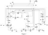
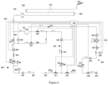
- some other embodiments of this disclosure further provide a firefighting foam foaming system, comprising an air supply flow path 200, a foam stock supply flow path 300, a water supply flow path 400 and a firefighting foam foaming device 100 provided by any one of the technical solutions of this disclosure.
- the air supply flow path 200 is located upstream of a second flow path 112 of the two-phase flow injection seat 110 to supply air to the two-phase flow injection seat 110.
- the foam stock supply flow path 300 is located upstream of the first inlet tube 140 to supply foam stock to the first inlet tube 140.
- the water supply flow path 400 is also located upstream of the first inlet tube 140 to supply water to the first inlet tube 140.
- the air supply flow path 200 comprises an air compressor 201, an air distribution valve 202 and a cooler 203. These parts are in fluid communication with each other via pipelines.
- the air compressor 201 is configured to supply compressed air.
- an intake throttle valve 209 can also be provided to adjust the intake air amount.
- a first air filter 204 can also be provided to filter impurities from air.
- a second air filter 205 is arranged downstream of the air compressor 201 to filter impurities in the compressed air output from the air compressor 201.
- a first pressure gauge 208 is provided on the pipeline between the air distribution valve 202 and the second air filter 205 for detecting the pressure within the pipeline.
- the air supply flow path 200 further includes an air flow meter 206.
- the air flow meter 206 is located downstream of the cooler 203. The flow of the compressed air in the pipeline is measured by the air flow meter 206.
- the air supply flow path 200 further comprises a one-way valve 207, which is located between the air flow meter 206 and the second flow path 112, so that the compressed air can only flow from the air flow meter 206 to the second flow path 112, but cannot flow back. Moreover, the possibility of the phenomenon of backflow of liquid from the first flow path to the air path in the firefighting foam foaming device 100 in some cases is eliminated.
- the firefighting foam foaming system further comprises a controller 850, which is in communication with the air compressor 201, the intake throttle valve 209, the first pressure gauge 208, the air distribution valve 202 and the air flow meter 206.
- the cooler 850 controls the working state of the air compressor 201, the intake throttle valve 209 and the air distribution valve 202 depending on fire extinguishing requirements, so that the parameters of the compressed air entered into the second flow path 112 of the two-phase flow injection seat 110 of the firefighting foam foaming device 100 meet the requirements.
- the parameters are e.g. flow, superficial velocity, also known as flow rate, etc.
- the foam stock supply flow path 300 is described below.
- the foam stock supply flow path 300 is used for supplying foam stock to the first flow path 111 of the two-phase flow injection seat 110 of the firefighting foam foaming device 100 as described above.
- the foam stock supply flow path 300 comprises a foam suction valve 301, a flushing water inlet valve 302 and a foam pump 303. These parts are in fluid communication with each other via pipelines.
- the foam pump 303 is used to pump foam. Upstream of the foam pump 303, two branches are provided: a foam stock suction branch 300a and a flushing branch 300b.
- the foam stock suction branch 300a is used to supply foam stock to the foam pump 303, and the flushing branch 300b provides flushing water to the foam pump 303 when individual components of the foam stock supply flow path 300 need to be flushed.
- the foam suction valve 301 is located in the foam stock suction branch 300a and is configured to communicate with a foam stock port 306.
- the flushing water inlet valve 302 is located in the flushing branch 300b and is configured to communicate with a flushing water port.
- the flushing water inlet valve 302 is arranged in parallel with the foam suction valve 301.
- the foam pump 303 is located downstream of the foam suction valve 301 and the flushing water inlet valve 302. According to demand, either the foam suction valve 301 or the flushing water inlet valve 302 is in the open state, and the fluid can flow through the valve in the open state.
- the foam stock supply flow path 300 comprises a check valve 304.
- the check valve 304 is used to make foam in the pipeline of the foam pump 303 flow in one direction and prevent the backflow.
- the foam stock supply flow path 300 comprises a foam flow meter 305.
- the foam flow meter 305 is used to detect the foam flow in the pipeline.
- the foam suction valve 301, the flushing water inlet valve 302, the foam pump 304, the foam flow meter 305 and the foam mixture switching valve 840 are all in communication with the controller 850.
- the cooler 850 is configured to control the respective working state of the foam suction valve 301, the flushing water inlet valve 302 and the foam pump 303 according to the state parameters detected by the water flow meter 406, the second pressure gauge 602, the second switching valve 601, the foam mixture switching valve 840, the foam flow meter 305 and the check valve 304 as well as the concrete fire extinguishing requirements.
- the firefighting foam foaming system can not only output water separately, but also output dry foam or wet foam.
- the firefighting foam foaming system further comprises a water supply flow path 400.
- the water supply flow path 400 includes a filter 400, a water pump 402, a vacuum pump 403 and a check valve 404.
- the parts which need fluid communication are fluidly communicated via pipelines.
- the water pump 402 is located downstream of the filter 401.
- the vacuum pump 403 is communicated with the pipeline between the filter 401 and the water pump 402 to extract air within that section of the line.
- the check valve 404 is located downstream of the water pump 402.
- the firefighting foam foaming system further comprises a water spray branch 500 and a foam spray branch 600.
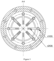
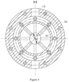
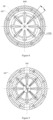
- baffles 702. there are 8 to 10 baffles 702.
- the individual baffles 702 are distributed uniformly in the circumferential direction of the main body 701.
- the maximum extension surface of the baffle 702 is parallel to the cross-section of the main body 701, as shown in Fig. 11 .
- the through hole 701a of the main body 701 has a diameter d1 at the inlet, and the main body 701 corresponding to the position where the baffle 702 is located has a diameter d2.
- the firefighting foam foaming system further comprises an injector 830.
- the injector 830 can be, for example, a fire cannon.
- the injector 830 is located at the downstream end of the delivery tube 810. Foam is finally delivered from the delivery tube 810 to the injector 830, and then is sprayed for fire suppression.
- the distance between the injector 830 and the firefighting foam generator 700 is greater than 5 to 10 times the maximum diameter of the pipeline between the firefighting foam generator 700 and the injector 830.
- the superficial velocity V F2 of foam in the delivery tube between the firefighting foam generator 700 and the injector 830 is 6 m/s to 12 m/s, so that the injector 830 sprays high-quality and uniform fire extinguishing foam.
- the length of the pipeline between the firefighting foam foaming device 100 and the firefighting foam generator 700 is greater than or equal to 10 to 20 times the maximum diameter of the pipeline, which is advantageous for the stable foam generation.
- the aforethe technical solution which is applicable to the large-flow compressed air foam system, features high foaming quality, small pressure loss in the pipeline, compact and delicate structure of foaming device, small space occupation, and is convenient for use and maintenance.
- the firefighting foam foaming method further comprises the step S400 of: delivering a fluid output by the firefighting foam foaming foamer 700 at a set fourth velocity V F2 to the injector 830.
- V F2 is 6 to 12 m/s.
- the above technical solution can reduce the pressure loss of the pipeline effectively, improve the foam quality and form a uniform bubble flow, and thus is especially suitable for a large-flow compressed air foam system.
Landscapes
- Health & Medical Sciences (AREA)
- Public Health (AREA)
- Business, Economics & Management (AREA)
- Emergency Management (AREA)
- Fire-Extinguishing By Fire Departments, And Fire-Extinguishing Equipment And Control Thereof (AREA)
Applications Claiming Priority (2)
| Application Number | Priority Date | Filing Date | Title |
|---|---|---|---|
| CN202211055005.5A CN115350426B (zh) | 2022-08-31 | 2022-08-31 | 消防泡沫发泡装置、系统以及发泡方法 |
| PCT/CN2022/121318 WO2024045249A1 (fr) | 2022-08-31 | 2022-09-26 | Appareil, système et procédé de moussage de mousse de lutte contre l'incendie |
Publications (1)
| Publication Number | Publication Date |
|---|---|
| EP4582149A1 true EP4582149A1 (fr) | 2025-07-09 |
Family
ID=84003837
Family Applications (1)
| Application Number | Title | Priority Date | Filing Date |
|---|---|---|---|
| EP22957068.4A Pending EP4582149A1 (fr) | 2022-08-31 | 2022-09-26 | Appareil, système et procédé de moussage de mousse de lutte contre l'incendie |
Country Status (3)
| Country | Link |
|---|---|
| EP (1) | EP4582149A1 (fr) |
| CN (1) | CN115350426B (fr) |
| WO (1) | WO2024045249A1 (fr) |
Families Citing this family (4)
| Publication number | Priority date | Publication date | Assignee | Title |
|---|---|---|---|---|
| CN115920280B (zh) * | 2022-11-29 | 2023-11-10 | 徐工消防安全装备有限公司 | 气液混合装置以及消防车 |
| CN116139435A (zh) * | 2023-02-21 | 2023-05-23 | 徐工消防安全装备有限公司 | 举高喷射消防车 |
| CN118857805B (zh) * | 2024-06-21 | 2025-09-26 | 国网安徽省电力有限公司电力科学研究院 | 一种适用于特高压变电站大跨度条件的压缩空气灭火系统测试平台及测试方法 |
| CN118698356B (zh) * | 2024-08-27 | 2025-01-10 | 山东世博金都药业有限公司 | 一种小分子团气泡水的制备系统及工艺 |
Family Cites Families (16)
| Publication number | Priority date | Publication date | Assignee | Title |
|---|---|---|---|---|
| US3428131A (en) * | 1966-08-16 | 1969-02-18 | Bliss Co | Method and apparatus for generating fire-fighting foam |
| JPH0715558U (ja) * | 1993-08-23 | 1995-03-14 | 東洋製罐株式会社 | 泡噴出ポンプ |
| EP1985333A1 (fr) * | 2007-04-27 | 2008-10-29 | Sogepi S.A. | Technologie améliorée de mousse à air comprimé |
| JP5556383B2 (ja) * | 2010-05-31 | 2014-07-23 | 花王株式会社 | 泡吐出容器 |
| AU2015354410A1 (en) * | 2014-11-28 | 2017-06-15 | Ofb Fire Solutions Pty Ltd | Fire-fighting system |
| GB201603949D0 (en) * | 2016-03-08 | 2016-04-20 | Rieke Packaging Systems Ltd | Foam dispensers |
| CN205964772U (zh) * | 2016-08-24 | 2017-02-22 | 南安市恒南消防器材有限公司 | 一种可调式消防泡沫枪 |
| CN106474950A (zh) * | 2016-10-25 | 2017-03-08 | 江苏大学镇江流体工程装备技术研究院 | 一种气液混合装置 |
| CN211634973U (zh) * | 2019-12-17 | 2020-10-09 | 徐工集团工程机械股份有限公司 | 泡沫均混管、混合泡沫灭火系统以及消防车 |
| CN110841222B (zh) * | 2019-12-17 | 2023-08-18 | 徐工集团工程机械股份有限公司 | 泡沫均混管、混合泡沫灭火系统及其控制方法以及消防车 |
| CN110975193B (zh) * | 2019-12-24 | 2024-05-28 | 磐龙安全技术有限公司 | 压缩空气泡沫流体混合装置 |
| CN215608929U (zh) * | 2020-12-31 | 2022-01-25 | 泰州市玉林动力机械有限公司 | 实时快速生成泡沫的气液比例混合器 |
| CN112546499B (zh) * | 2020-12-31 | 2023-11-10 | 泰州市玉林动力机械有限公司 | 一种移动式压缩空气泡沫灭火装备 |
| CN113332642A (zh) * | 2021-07-09 | 2021-09-03 | 西安忠舍天域新能源安全技术有限公司 | 小型化高倍数消防泡沫发生器 |
| CN115364407B (zh) * | 2022-08-31 | 2023-07-25 | 徐工消防安全装备有限公司 | 伸缩式消防泡沫发泡器、系统以及发泡方法 |
| CN115350427B (zh) * | 2022-08-31 | 2023-12-15 | 徐工消防安全装备有限公司 | 消防泡沫发泡器、系统以及发泡方法 |
-
2022
- 2022-08-31 CN CN202211055005.5A patent/CN115350426B/zh active Active
- 2022-09-26 WO PCT/CN2022/121318 patent/WO2024045249A1/fr not_active Ceased
- 2022-09-26 EP EP22957068.4A patent/EP4582149A1/fr active Pending
Also Published As
| Publication number | Publication date |
|---|---|
| CN115350426A (zh) | 2022-11-18 |
| CN115350426B (zh) | 2023-07-07 |
| WO2024045249A1 (fr) | 2024-03-07 |
Similar Documents
| Publication | Publication Date | Title |
|---|---|---|
| EP4582149A1 (fr) | Appareil, système et procédé de moussage de mousse de lutte contre l'incendie | |
| US5484107A (en) | Three-fluid atomizer | |
| CN115350427B (zh) | 消防泡沫发泡器、系统以及发泡方法 | |
| US4993495A (en) | Apparatus for applying firefighting chemicals | |
| KR20030019346A (ko) | 차등 분사기 | |
| US4828038A (en) | Foam fire fighting apparatus | |
| CN103055455B (zh) | 一种多功能压缩空气泡沫灭火装置 | |
| JP4426612B2 (ja) | 微細気泡発生ノズル | |
| CN115364407B (zh) | 伸缩式消防泡沫发泡器、系统以及发泡方法 | |
| EP3878524A1 (fr) | Dispositif de production d'un mélange de gaz-liquide destiné à des fins de lutte contre l'incendie | |
| CN206026937U (zh) | 一种自吸式空气泡沫枪 | |
| US20170259091A1 (en) | Fire-fighting system | |
| CN105771720B (zh) | 一种喷雾型气液静态混合器 | |
| CN203090319U (zh) | 一种多功能压缩空气泡沫灭火装置 | |
| JPH07328402A (ja) | 気液溶解混合装置 | |
| JPS5941780B2 (ja) | 流体の複合噴流方法と複合ノズルユニツト | |
| JPH0712327A (ja) | ディーゼル燃料及び水の乳化のための乳化装置 | |
| JPH01189340A (ja) | 泡製造装置 | |
| WO2024174532A1 (fr) | Véhicule de lutte contre l'incendie à tour d'eau | |
| CN116020072A (zh) | 消防炮以及灭火喷射系统 | |
| KR101402520B1 (ko) | 포소화액 혼합분사장치 | |
| US8561972B2 (en) | Low pressure gas transfer device | |
| RU2304993C2 (ru) | Смеситель и устройство пожаротушения | |
| EA049420B1 (ru) | Телескопический пенообразователь противопожарной пены, система пенообразования и способ пенообразования | |
| CN2722962Y (zh) | 压缩空气a类泡沫灭火装置 |
Legal Events
| Date | Code | Title | Description |
|---|---|---|---|
| STAA | Information on the status of an ep patent application or granted ep patent |
Free format text: STATUS: THE INTERNATIONAL PUBLICATION HAS BEEN MADE |
|
| PUAI | Public reference made under article 153(3) epc to a published international application that has entered the european phase |
Free format text: ORIGINAL CODE: 0009012 |
|
| STAA | Information on the status of an ep patent application or granted ep patent |
Free format text: STATUS: REQUEST FOR EXAMINATION WAS MADE |
|
| 17P | Request for examination filed |
Effective date: 20250306 |
|
| AK | Designated contracting states |
Kind code of ref document: A1 Designated state(s): AL AT BE BG CH CY CZ DE DK EE ES FI FR GB GR HR HU IE IS IT LI LT LU LV MC MK MT NL NO PL PT RO RS SE SI SK SM TR |
|
| DAV | Request for validation of the european patent (deleted) | ||
| DAX | Request for extension of the european patent (deleted) |