EP2116324B1 - Dispositif de transmission sans fil de signaux entre deux parties d'une machine de traitement - Google Patents
Dispositif de transmission sans fil de signaux entre deux parties d'une machine de traitement Download PDFInfo
- Publication number
- EP2116324B1 EP2116324B1 EP09153038A EP09153038A EP2116324B1 EP 2116324 B1 EP2116324 B1 EP 2116324B1 EP 09153038 A EP09153038 A EP 09153038A EP 09153038 A EP09153038 A EP 09153038A EP 2116324 B1 EP2116324 B1 EP 2116324B1
- Authority
- EP
- European Patent Office
- Prior art keywords
- antennas
- signals
- antenna
- individual
- circumferential direction
- Prior art date
- Legal status (The legal status is an assumption and is not a legal conclusion. Google has not performed a legal analysis and makes no representation as to the accuracy of the status listed.)
- Active
Links
Images


Classifications
-
- B—PERFORMING OPERATIONS; TRANSPORTING
- B23—MACHINE TOOLS; METAL-WORKING NOT OTHERWISE PROVIDED FOR
- B23Q—DETAILS, COMPONENTS, OR ACCESSORIES FOR MACHINE TOOLS, e.g. ARRANGEMENTS FOR COPYING OR CONTROLLING; MACHINE TOOLS IN GENERAL CHARACTERISED BY THE CONSTRUCTION OF PARTICULAR DETAILS OR COMPONENTS; COMBINATIONS OR ASSOCIATIONS OF METAL-WORKING MACHINES, NOT DIRECTED TO A PARTICULAR RESULT
- B23Q17/00—Arrangements for observing, indicating or measuring on machine tools
-
- B—PERFORMING OPERATIONS; TRANSPORTING
- B23—MACHINE TOOLS; METAL-WORKING NOT OTHERWISE PROVIDED FOR
- B23Q—DETAILS, COMPONENTS, OR ACCESSORIES FOR MACHINE TOOLS, e.g. ARRANGEMENTS FOR COPYING OR CONTROLLING; MACHINE TOOLS IN GENERAL CHARACTERISED BY THE CONSTRUCTION OF PARTICULAR DETAILS OR COMPONENTS; COMBINATIONS OR ASSOCIATIONS OF METAL-WORKING MACHINES, NOT DIRECTED TO A PARTICULAR RESULT
- B23Q1/00—Members which are comprised in the general build-up of a form of machine, particularly relatively large fixed members
- B23Q1/0009—Energy-transferring means or control lines for movable machine parts; Control panels or boxes; Control parts
- B23Q1/0018—Energy-transferring means or control lines for movable machine parts; Control panels or boxes; Control parts comprising hydraulic means
- B23Q1/0027—Energy-transferring means or control lines for movable machine parts; Control panels or boxes; Control parts comprising hydraulic means between moving parts between which an uninterrupted energy-transfer connection is maintained
-
- H—ELECTRICITY
- H01—ELECTRIC ELEMENTS
- H01F—MAGNETS; INDUCTANCES; TRANSFORMERS; SELECTION OF MATERIALS FOR THEIR MAGNETIC PROPERTIES
- H01F38/00—Adaptations of transformers or inductances for specific applications or functions
- H01F38/18—Rotary transformers
-
- H—ELECTRICITY
- H04—ELECTRIC COMMUNICATION TECHNIQUE
- H04B—TRANSMISSION
- H04B7/00—Radio transmission systems, i.e. using radiation field
- H04B7/02—Diversity systems; Multi-antenna system, i.e. transmission or reception using multiple antennas
- H04B7/04—Diversity systems; Multi-antenna system, i.e. transmission or reception using multiple antennas using two or more spaced independent antennas
- H04B7/06—Diversity systems; Multi-antenna system, i.e. transmission or reception using multiple antennas using two or more spaced independent antennas at the transmitting station
- H04B7/0613—Diversity systems; Multi-antenna system, i.e. transmission or reception using multiple antennas using two or more spaced independent antennas at the transmitting station using simultaneous transmission
- H04B7/0682—Diversity systems; Multi-antenna system, i.e. transmission or reception using multiple antennas using two or more spaced independent antennas at the transmitting station using simultaneous transmission using phase diversity (e.g. phase sweeping)
-
- H—ELECTRICITY
- H01—ELECTRIC ELEMENTS
- H01F—MAGNETS; INDUCTANCES; TRANSFORMERS; SELECTION OF MATERIALS FOR THEIR MAGNETIC PROPERTIES
- H01F38/00—Adaptations of transformers or inductances for specific applications or functions
- H01F38/14—Inductive couplings
- H01F2038/143—Inductive couplings for signals
Definitions
- the invention relates to a device for the wireless transmission of signals according to the preamble of claim 1.
- a device for the wireless transmission of signals according to the preamble of claim 1.
- Such a device is known from DE 20 2004 016 751 A1 in which the optimization of inductively coupled transponder systems for the field of mechanical and plant engineering is described.
- the use of high-permeability material is proposed, which prevents the penetration of the magnetic field lines into metal and ensures their function under these environmental conditions.
- the emission or reception characteristic of the respective antenna on the rotor and / or the stator essentially determines the quality of the data transmission. Desirable here is the most constant transmission or reception quality in each angular position. Suboptimal transmission and / or reception quality leads directly to an increase in the error rate during data transmission.
- a wire loop which is adapted to the transmission or reception frequency and the geometric boundary conditions and runs in the circumferential direction of the rotor or of the stator has physically one or more radiation or reception minima along its circumferential direction.
- radio receiver modules have a variable amplifier in the antenna input area, whose amplification factor is adapted to the received signal by means of a control loop.
- This control has a transient response, which interferes with the data transmission at higher rotational speeds, so that in many cases no reception or only a reception with a high error rate is possible.
- the error rate can be reduced by the use of coding methods which enable error detection (eg CRC check), as well as by multiple data transmission, ie by multiple transmission of the individual data words to be transmitted.
- CRC check error detection
- the object of the invention is therefore to provide an antenna arrangement for a generic device, which enables trouble-free data transmission with a high data rate.
- the invention is based on the combination of a plurality of antennas, of which none by itself the desired radially symmetric radiation or reception characteristic with respect to the two by a wireless transmission link to connecting machine parts, however, their individual characteristics result in an interconnected antennas and appropriate power supply on the transmitter side or suitable superimposition of the individual signals on the receiver side an approximately radially symmetric overall characteristic of the transmission.
- it is sufficient to use such an antenna combination either on the transmitter side or on the receiver side, but the effect can be further increased by using it on both sides.
- a first expedient variant of the realization consists in a mutual spatial overlap of the individual antennas in the circumferential direction of the rotation. Such an overlap leads, with a suitable choice of the mutual offset of the individual antennas in said circumferential direction, by a corresponding superimposition of the individual transfer characteristics to an overall characteristic with substantially less pronounced extremes.
- a second expedient variant of the realization consists in a supply of a plurality of transmitting antennas, which is phase-shifted in the circumferential direction of rotation, and / or a correspondingly phase-shifted superimposition of the received signals of a plurality of receiving antennas.
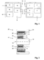
- FIG. 1 A block diagram of such a sensor system shows Fig. 1 , It is located on a rotating part in operation of the machine, hereinafter referred rotor, the rotor electronics 1. It includes as essential functional units one or more sensors 2, z. As strain gauges, a Scnsorsignalaufpung 3, a microcontroller 4, a power converter 5 with a secondary coil 6 for inductive supply of the remaining units with electrical power and a radio module 7 with an antenna 8 for external communication, in particular the transmission crutzter measurement data.
- Statorclektronik 9 On a fixed part of the machine, hereinafter referred to as Stator, is the Statorclektronik 9. It comprises as essential functional units a power converter 10 for inductive delivery of electrical power to the rotor electronics 1 via a primary coil 11, a radio module 12 with an antenna 13 for communication with the Rotor electronics 1, a power converter 14 for receiving electrical power from a power supply of the machine, not shown, a microcontroller 15, and an interface 16 for passing the measured by the sensor 2 and transmitted to the stator electronics 9 data to a higher-level machine control.
- a power converter 10 for inductive delivery of electrical power to the rotor electronics 1 via a primary coil 11, a radio module 12 with an antenna 13 for communication with the Rotor electronics 1, a power converter 14 for receiving electrical power from a power supply of the machine, not shown, a microcontroller 15, and an interface 16 for passing the measured by the sensor 2 and transmitted to the stator electronics 9 data to a higher-level machine control.
- the sensor system is based on per se known transponder technology, the power in the rotor electronics 1 inductively coupled, for example, at a frequency in the order of 30 kHz and the recorded measurement data by radio, for example, at a frequency in the order of 2.4 GHz or in a other ISM band to the stator electronics 9 are sent.
- FIG Fig. 2 A longitudinal sectional view of parts of a processing machine equipped with such a wireless sensor system is shown in FIG Fig. 2 to see.
- the rotor 17 rotates during operation of the machine about an axis 18. It comprises a cylindrical shaft or spindle 19 made of metal, on which the rotor electronics 1 is mounted.
- the components 20 are mounted on a flexible, around the spindle 19 in the circumferential direction guided around substrate 21 and surrounded by the secondary coil 6, whose axis coincides with the axis 18 of the spindle 19.
- the antenna 8 of the rotor electronics 1 forms the radially outermost element of the rotor electronics 1, which is embedded in total in an integral with the spindle 19 inner support body 22 made of plastic.
- the stator 23 comprises a metal mechanical machine element 24, on the inside of an outer support body 25 made of plastic in the form of a hollow cylinder is fixedly mounted. Between the inner support body 22 and the outer support body 25 there is an air gap 26 of constant width along the circumference. Embedded in the outer carrier body 25 are the primary coil 11 and the antenna 13 of the stator electronics 9, wherein the antenna 13 is arranged radially further inward than the primary coil 11. The rest, in Fig. 2 not shown components of the stator electronics 9 may also be arranged directly on the stator 23, for example, be embedded in the outer support body 25, but may also be placed elsewhere on the machine off the stator 23.
- FIG. 3 A first antenna arrangement embodying the present invention is shown Fig. 3 in the form of a block diagram. Subsequently, it is initially assumed that it is a transmission-side antenna arrangement. How out Fig. 3 can be seen, three different mutually similar loop antennas 8A, 8B and 8C are provided. each of them is connected via a respective adjustment member 27A, 27B and 27C and a supply line 28A, 28B and 28C to a common branch member 29.
- Adaptation members 27A, 27B and 27C are so-called baluns known per se for adapting symmetrical loop antennas 8A, 8B and 8C to unbalanced leads 28A, 28B and 28C, respectively, in the interest of simplifying signal processing.
- a feature of the invention lies in the geometric arrangement of the three loop antennas 8A, 8B and 8C, which in Fig. 4 is shown schematically.
- the three loop antennas 8A, 8B and 8C are arranged radially concentric with the axis 18 and their bases 30A, 30B and 30C, at which they are each angled radially, are continuously offset from each other by an angle of 120 °.
- the others in the Figures 2 and 3 shown components are in Fig. 4 omitted for clarity.
- the arrangement after Fig. 4 is regular and symmetrical with respect to the positions of the roots 30A, 30B and 30C in the circumferential direction.
- the loop antennas 8A, 8B and 8C could be offset from each other even with the same diameter in the longitudinal direction of the axis 18. It is essential that the in Fig. 4 The apparent difference in diameter, or the alternatively possible offset in the longitudinal direction of the axis 18, is small compared to the mean diameter, so that it does not significantly affect the radiation characteristic, ie all three loop antennas 8A, 8B and 8C apart from the different positions of the foot points 30A , 30B and 30C have substantially the same emission characteristic.
- leads 28A, 28B and 28C are connected via first resistors to ground and via second resistors to a common neutral point 31 at which the common data signal to be radiated by the three loop antennas 8A, 8B and 8C is coupled.
- the invention can also be applied to the receiving side.
- the individual antennas 8A, 8B and 8C would be receiving antennas.
- the individual antennas 8A, 8B and 8C would be receiving antennas.
- the antennas 8A, 8B and 8C according to FIG. 3 and FIG. 5 and in terms of their geometric arrangement relative to each other Fig. 4 however, nothing would change on the receiving side except for the signal flow direction.
- a signal would be emitted in this case for further processing instead of being fed to the radiation.
- minima of the radial receiving characteristic exist in the region of the respective base points, which in turn would be largely compensated by the overlap and the regular symmetrical angular offset of the individual antennas.
- the distance between the transmitter and receiver is very small, so that the near field and not the Femfeld is decisive for the spatial radiation or reception characteristics of the antennas.
- the field progression is further enhanced by the metallic environment (spindle 19, machine element 24), i. their reflective behavior, significantly affects what must be taken into account in the exact dimensioning of the antenna arrangement.
- a second antenna arrangement embodying the present invention shows Fig. 6 in the form of a block diagram.
- Fig. 6 it is initially assumed that it is a transmitting antenna arrangement.
- Fig. 6 As can be seen, three different dipole antennas 108A, 108B and 108C are provided. Each of them is connected via a respective matching member 127A, 127B and 127C and a lead 128A, 128B and 128C, respectively, to a common branching member 129, which is similar to the one shown in FIG Fig. 5 shown Verze Trentsglied 29 is constructed.
- the adapters 127A, 127B, and 127C are baluns for matching the balanced dipole antennas 108A, 108B, and 108C to the single ended leads 128A, 128B, and 128C, respectively, in the interest of simplifying signal processing.
- a first feature of the invention is the arrangement of delay elements 132B and 132C, for example in the form of delay lines, in the leads 128B and 128C, respectively.
- the individual dipole antennas 108A, 108B and 108C thus receive the same signal for radiation, but this is not in phase, but with a defined mutual phase shift fed, which makes 120 ° continuously, ie for the antenna 108B relative to the antenna 108A 120 ° and for the Antenna 108C opposite the antenna 108A is 240 °. It may also be appropriate not to select the same value for the phase shift between successive antennas in all cases, but to provide targeted deviations to thereby compensate for irregularities of the radiation field, resulting from irregularities in the shape of the metallic environment, for example in the form of holes ,
- a further feature according to the invention lies in the geometric arrangement of the three mutually identical dipole antennas 108A, 108B and 108C, which are described in US Pat Fig. 7 is shown schematically.
- the three dipole antennas 108A, 108B and 108C are juxtaposed on an axis 18 of the spindle 19 (FIGS. Fig. 2 ) is arranged as a center-running circle and continuously circumferentially offset by an angle of 120 ° each so that each of the dipole antennas 108A, 108B and 108C covers a sector of about 120 °.
- the superposition of these signals provides a substantial balance of the minimum radiating characteristics of each individual dipole antenna 108A, 108B and 108C, so that approx uniform overall radial characteristic of the radiation results.
- Fig. 8 shows by way of example a symmetrical circular arrangement of three dipole antennas 13A, 13B and 13C, which are receiving antennas.
- a radial radiation pattern of a conventional type is drawn for a single dipole antenna.
- the power density P D is given as a function of the direction.
- the illustrated course P D for a special Angular position of the dipole, has a pronounced minimum M.
- a single dipole antenna with the illustrated radiation characteristic P D is provided as the sole transmitting antenna on the rotor 17, and that the three dipole antennas 13A, 13B and 13C are provided as receiving antennas on the stator 23, the latter being wired as well the dipole antennas 108A, 108B and 108C in FIG Fig. 6 and only the signal flow direction is reversed.
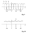
- Fig. 9 shows the course of the signal strengths S A , S B and S C of the received signals of the three receiving antennas 13 A , 13 B and 13 C as a function of the rotation angle ⁇ of the transmission antenna provided as a dipole. It can be seen in each case pronounced maxima and minima, the position of the abscissa in Fig. 9 was chosen arbitrarily and does not represent a zero line. Adding the three received signals S A , S B and S C with a continuous phase shift of 120 ° each using a branching element in the manner of Fig. 5 , then qualitatively the results in Fig. 10 illustrated course of the resulting signal strength S R over the rotation angle ⁇ of the transmitting antenna.
- Such a signal would be at star point 131 of the circuit Fig. 6 when the transmitting antennas 108A, 108B and 108C are replaced by the receiving antennas 13A, 13B and 13C.
- the course of S R still has a slight ripple, it is far more uniform than any one of the courses of S A , S B and S C.
- the overlap in the circumferential direction does not have to be nearly 360 ° as in the case of the loop antennas of the first embodiment, but it may also be an overlapping arrangement of other antenna shapes such as B. be provided by dipoles, in which the extent of overlap can be significantly lower.
- the two embodiments explained here can also be combined with each other, ie it may also be useful in the case of an overlapping arrangement to additionally provide a phase shift of the signals.
- the number of three antennas provided in the exemplary embodiments is of course meant to be purely exemplary and can be varied according to the requirements and framework conditions (space conditions, cost expenditure) of the individual application.
- the communication between the rotor electronics 1 and the stator electronics 9 can also be bidirectional, for example for activating certain functions of the rotor electronics 1, such as a self-test of the sensor 2, from the stator electronics 9.
Landscapes
- Engineering & Computer Science (AREA)
- Mechanical Engineering (AREA)
- Power Engineering (AREA)
- Computer Networks & Wireless Communication (AREA)
- Signal Processing (AREA)
- Arrangements For Transmission Of Measured Signals (AREA)
- Radio Transmission System (AREA)
- Waveguide Connection Structure (AREA)
- Variable-Direction Aerials And Aerial Arrays (AREA)
Claims (7)
- Dispositif de transmission de signaux, sans fil, entre deux parties (17, 23) d'une machine de traitement dont l'une tourne par rapport à l'autre autour d'un axe (18), au cours du fonctionnement de ladite machine de traitement, caractérisé par le fait que plusieurs antennes (8A, 8B, 8C ; 108A, 108B, 108C ; 13A, 13B, 13C) sont implantées sur au moins l'une des deux parties (17, 23), avec répartition au moins approximativement régulière vis-à-vis de la direction périphérique de la rotation ; et par le fait que lesdites antennes (8A, 8B, 8C ; 108A, 108B, 108C ; 13A, 13B, 13C) sont raccordées à un système émetteur (7) et/ou à un système récepteur (12) assigné à la partie (17, 23) considérée, en parallèle les unes avec les autres, en vue d'atteindre une caractéristique globale de la transmission présentant, approximativement, une symétrie radiale.
- Dispositif selon la revendication 1, caractérisé par le fait que plusieurs antennes (8A, 8B, 8C ; 108A, 108B, 108C ; 13A, 13B, 13C) sont implantées à chaque fois, sur les deux parties (17, 23) de la machine de traitement, avec répartition au moins approximativement régulière vis-à-vis de la direction périphérique de la rotation.
- Dispositif selon la revendication 1 ou 2, caractérisé par le fait que les antennes individuelles (8A, 8B, 8C ; 108A, 108B, 108C ; 13A, 13B, 13C), implantées sur la même partie de la machine de traitement, offrent réciproquement la même forme et sont décalées, dans le sens périphérique, d'un angle mesurant au moins approximativement 360° divisé par le nombre desdites antennes (8A, 8B, 8C ; 108A, 108B, 108C ; 13A, 13B, 13C).
- Dispositif selon l'une des revendications 1 à 3, caractérisé par le fait que les longueurs des antennes individuelles (8A, 8B, 8C) se chevauchent dans la direction périphérique de la rotation et lesdites antennes individuelles sont agencées, au moins partiellement, avec décalage mutuel dans le sens radial et/ou dans la direction longitudinale de l'axe de rotation (18).
- Dispositif selon l'une des revendications 1 à 4, caractérisé par le fait que des signaux de même phase sont introduits dans les antennes individuelles (8A, 8B, 8C) par le système émetteur (7) ; et des signaux reçus en provenance desdites antennes individuelles sont mutuellement superposés, par le système récepteur (12), avec identité de phase.
- Dispositif selon l'une des revendications 1 à 4, caractérisé par le fait que des signaux à phase décalée sont introduits dans les antennes individuelles (108A, 108B, 108C) par le système émetteur ; et/ou des signaux reçus en provenance desdites antennes individuelles (108A, 108B, 108C) sont mutuellement superposés, par le système récepteur, avec décalage de phase.
- Dispositif selon la revendication 6, caractérisé par le fait que le décalage de phase mesure au moins approximativement 360° divisé par le nombre des antennes (108A, 108B, 108C ; 13A, 13B, 13C).
Applications Claiming Priority (1)
| Application Number | Priority Date | Filing Date | Title |
|---|---|---|---|
| DE102008023224A DE102008023224A1 (de) | 2008-05-10 | 2008-05-10 | Vorrichtung zur drahtlosen Übertragung von Signalen zwischen zwei Teilen einer Bearbeitungsmaschine |
Publications (2)
| Publication Number | Publication Date |
|---|---|
| EP2116324A1 EP2116324A1 (fr) | 2009-11-11 |
| EP2116324B1 true EP2116324B1 (fr) | 2010-12-22 |
Family
ID=40874635
Family Applications (1)
| Application Number | Title | Priority Date | Filing Date |
|---|---|---|---|
| EP09153038A Active EP2116324B1 (fr) | 2008-05-10 | 2009-02-17 | Dispositif de transmission sans fil de signaux entre deux parties d'une machine de traitement |
Country Status (5)
| Country | Link |
|---|---|
| US (1) | US20090280743A1 (fr) |
| EP (1) | EP2116324B1 (fr) |
| JP (1) | JP2009273129A (fr) |
| DE (2) | DE102008023224A1 (fr) |
| ES (1) | ES2353838T3 (fr) |
Cited By (1)
| Publication number | Priority date | Publication date | Assignee | Title |
|---|---|---|---|---|
| DE102018000030A1 (de) | 2018-01-03 | 2019-07-04 | Hottinger Baldwin Messtechnik Gmbh | System für drahtloses Versorgen einer rotierenden Vorrichtung mit elektrischer Energie |
Families Citing this family (10)
| Publication number | Priority date | Publication date | Assignee | Title |
|---|---|---|---|---|
| DE102010052676B4 (de) | 2010-11-25 | 2013-07-25 | Hohenstein Vorrichtungsbau Und Spannsysteme Gmbh | Verfahren zur Werkstück-Positionierung und -Fixierung |
| DE102012000762A1 (de) | 2012-01-18 | 2013-07-18 | Ott-Jakob Spanntechnik Gmbh | Antennenabdeckung |
| US9484791B2 (en) * | 2012-08-08 | 2016-11-01 | Infineon Technologies Ag | Remote rotor parameter sensor for electric drives |
| DE102012219099A1 (de) | 2012-10-19 | 2014-04-24 | Kadia Produktion Gmbh + Co. | Honmaschine |
| WO2014118901A1 (fr) * | 2013-01-30 | 2014-08-07 | 株式会社日立製作所 | Appareil de communication utilisant des ondes radio entre un rotor et un stator |
| JP6220239B2 (ja) | 2013-11-13 | 2017-10-25 | キヤノン株式会社 | 電磁波検出・発生装置 |
| WO2015173890A1 (fr) * | 2014-05-13 | 2015-11-19 | 三菱電機エンジニアリング株式会社 | Systeme de transmission a partie mobile utilisant une transmission d'energie sans fil |
| MY173106A (en) * | 2014-07-18 | 2019-12-26 | Ukm Tech Sdn Bhd | Integrated rotating dynamometer for milling or drilling process |
| US9668084B2 (en) * | 2015-05-08 | 2017-05-30 | Dexter Laundry, Inc. | Wireless communication assembly |
| JP7126456B2 (ja) | 2016-08-12 | 2022-08-26 | ビッグ カイザー プレツィヅィオンスヴェルクツォイク アーゲー | 電子ユニットを有するボーリング・ヘッド |
Family Cites Families (10)
| Publication number | Priority date | Publication date | Assignee | Title |
|---|---|---|---|---|
| JPH02184241A (ja) * | 1989-01-09 | 1990-07-18 | Hitachi Constr Mach Co Ltd | 回転体内の電気回路の電源装置 |
| JP3388809B2 (ja) * | 1992-10-29 | 2003-03-24 | 大日本印刷株式会社 | 信号伝送装置 |
| JP3359684B2 (ja) * | 1993-03-03 | 2002-12-24 | 大日本印刷株式会社 | 信号伝送装置 |
| JP2000052196A (ja) * | 1998-08-08 | 2000-02-22 | Nt Engineering Kk | 作業機械およびその通信方法 |
| JP2002163744A (ja) * | 2000-09-13 | 2002-06-07 | Natl Inst Of Industrial Safety Independent Administrative Institution | 回転体用リング型信号伝送装置 |
| DE102004010348A1 (de) * | 2004-03-03 | 2005-09-22 | Meri Entsorgungstechnik für die Papierindustrie GmbH | Verschleißerfassung durch Transponderzerstörung |
| DE102004032022A1 (de) * | 2004-07-01 | 2006-01-19 | Walter Dittel Gmbh | Signalübertragung |
| DE202004016751U1 (de) | 2004-10-28 | 2005-01-27 | Pro-Micron Gmbh & Co. Kg Modular Systems | Transpondersystem |
| DE102005027632B4 (de) * | 2005-03-31 | 2009-09-24 | Schleifring Und Apparatebau Gmbh | Mehrkanal-Datenübertragungssystem für Computertomographen |
| US7717619B2 (en) * | 2008-01-18 | 2010-05-18 | General Electric Company | Contactless power and data transmission apparatus |
-
2008
- 2008-05-10 DE DE102008023224A patent/DE102008023224A1/de not_active Withdrawn
-
2009
- 2009-02-17 EP EP09153038A patent/EP2116324B1/fr active Active
- 2009-02-17 DE DE502009000232T patent/DE502009000232D1/de active Active
- 2009-02-17 ES ES09153038T patent/ES2353838T3/es active Active
- 2009-03-09 US US12/400,498 patent/US20090280743A1/en not_active Abandoned
- 2009-04-30 JP JP2009110349A patent/JP2009273129A/ja active Pending
Cited By (2)
| Publication number | Priority date | Publication date | Assignee | Title |
|---|---|---|---|---|
| DE102018000030A1 (de) | 2018-01-03 | 2019-07-04 | Hottinger Baldwin Messtechnik Gmbh | System für drahtloses Versorgen einer rotierenden Vorrichtung mit elektrischer Energie |
| DE102018000030B4 (de) | 2018-01-03 | 2023-03-30 | Hottinger Brüel & Kjaer GmbH | System für drahtloses Versorgen einer rotierenden Vorrichtung mit elektrischer Energie |
Also Published As
| Publication number | Publication date |
|---|---|
| ES2353838T3 (es) | 2011-03-07 |
| EP2116324A1 (fr) | 2009-11-11 |
| JP2009273129A (ja) | 2009-11-19 |
| DE102008023224A1 (de) | 2009-11-12 |
| US20090280743A1 (en) | 2009-11-12 |
| DE502009000232D1 (de) | 2011-02-03 |
Similar Documents
| Publication | Publication Date | Title |
|---|---|---|
| EP2116324B1 (fr) | Dispositif de transmission sans fil de signaux entre deux parties d'une machine de traitement | |
| DE69630627T2 (de) | Mehrschleifenantenne | |
| EP3070723B1 (fr) | Dispositif de transmission de donnees et d'energie entre deux objets se deplaçant l'un par rapport a l'autre | |
| EP1208614A1 (fr) | Ensemble dephaseur a haute frequence | |
| EP3179638B1 (fr) | Dispositif de transmission sans contact de donnees et destiné à déterminer la modification angulaire entre deux objets se deplaçant l'un par rapport à l'autre | |
| DE102018113476B4 (de) | Vorrichtung und verfahren zur drehmomentmessung | |
| DE102014016367A1 (de) | Antennengruppe mit asymmetrischen Antennenelementen | |
| DE1953443B2 (de) | Sendeantennensystem fur ein Funkfeuer | |
| EP2893359B1 (fr) | Palier résolveur | |
| WO2015180711A1 (fr) | Palier de résolveur, stator de résolveur et procédé de fabrication | |
| EP2965382B1 (fr) | Système d'antennes à caractéristique directionnelle variable | |
| DE102016100441B4 (de) | Empfangskoppler für eine kontaktlose Datenübertragungsstrecke | |
| EP3734565B1 (fr) | Machine de construction | |
| DE102010001484A1 (de) | Übertragungsvorrichtung zur kontaktlosen Übertragung von Energie und Daten, Übertragungssystem und Verfahren zur kontaktlosen induktiven Energieübertragung und Datenübertragung | |
| DE2458477A1 (de) | Mechanischer mehrkanal-phasenschieber | |
| DE19928216C2 (de) | Telemetrie-Spulenanordnung zum Empfang von Datensignalen insbesondere von kardiologischen Implantaten | |
| DE102022115502B3 (de) | Vorrichtung zur Erfassung von Messwerten in einer Maschine und kontaktlosen Signalübertragung, sowie Maschinenbaugruppe mit dieser Vorrichtung | |
| EP3104128B1 (fr) | Dispositif de transmission sans contact de donnees et destine a determiner la modification angulaire entre deux objets se deplaçant l'un par rapport a l'autre | |
| DE2707819A1 (de) | Spiralelementenantenne | |
| DE4125143C2 (de) | Einrichtung zur kontaktlosen Übertragung von Wechselsignalen | |
| DE202009001428U1 (de) | Vorrichtung zur drahtlosen Übertragung von Signalen zwischen zwei Teilen einer Bearbeitungsmaschine | |
| EP3622254B1 (fr) | Dispositif de mesure pour mesurer une position et/ou une vitesse de rotation d'un arbre rotatif | |
| EP3179637A2 (fr) | Dispositif de transmission sans contact de donnees et destiné à déterminer la modification angulaire entre deux objets se deplaçant l'un par rapport à l'autre | |
| EP4369617B1 (fr) | Machine d'usinage mécanique avec élément rotatif | |
| EP3894792B1 (fr) | Détection inductive d'un angle de rotation |
Legal Events
| Date | Code | Title | Description |
|---|---|---|---|
| PUAI | Public reference made under article 153(3) epc to a published international application that has entered the european phase |
Free format text: ORIGINAL CODE: 0009012 |
|
| AK | Designated contracting states |
Kind code of ref document: A1 Designated state(s): AT BE BG CH CY CZ DE DK EE ES FI FR GB GR HR HU IE IS IT LI LT LU LV MC MK MT NL NO PL PT RO SE SI SK TR |
|
| AX | Request for extension of the european patent |
Extension state: AL BA RS |
|
| 17P | Request for examination filed |
Effective date: 20091022 |
|
| 17Q | First examination report despatched |
Effective date: 20100212 |
|
| AKX | Designation fees paid |
Designated state(s): CH DE ES IT LI |
|
| GRAP | Despatch of communication of intention to grant a patent |
Free format text: ORIGINAL CODE: EPIDOSNIGR1 |
|
| GRAS | Grant fee paid |
Free format text: ORIGINAL CODE: EPIDOSNIGR3 |
|
| GRAA | (expected) grant |
Free format text: ORIGINAL CODE: 0009210 |
|
| AK | Designated contracting states |
Kind code of ref document: B1 Designated state(s): CH DE ES IT LI |
|
| REG | Reference to a national code |
Ref country code: CH Ref legal event code: EP Ref country code: CH Ref legal event code: NV Representative=s name: LUCHS & PARTNER AG PATENTANWAELTE |
|
| REF | Corresponds to: |
Ref document number: 502009000232 Country of ref document: DE Date of ref document: 20110203 Kind code of ref document: P |
|
| REG | Reference to a national code |
Ref country code: DE Ref legal event code: R096 Ref document number: 502009000232 Country of ref document: DE Effective date: 20110203 |
|
| REG | Reference to a national code |
Ref country code: ES Ref legal event code: FG2A Effective date: 20110223 |
|
| PLBE | No opposition filed within time limit |
Free format text: ORIGINAL CODE: 0009261 |
|
| STAA | Information on the status of an ep patent application or granted ep patent |
Free format text: STATUS: NO OPPOSITION FILED WITHIN TIME LIMIT |
|
| 26N | No opposition filed |
Effective date: 20110923 |
|
| REG | Reference to a national code |
Ref country code: DE Ref legal event code: R097 Ref document number: 502009000232 Country of ref document: DE Effective date: 20110923 |
|
| PGFP | Annual fee paid to national office [announced via postgrant information from national office to epo] |
Ref country code: ES Payment date: 20230317 Year of fee payment: 15 Ref country code: CH Payment date: 20230307 Year of fee payment: 15 |
|
| PGFP | Annual fee paid to national office [announced via postgrant information from national office to epo] |
Ref country code: IT Payment date: 20230228 Year of fee payment: 15 |
|
| PGFP | Annual fee paid to national office [announced via postgrant information from national office to epo] |
Ref country code: DE Payment date: 20240405 Year of fee payment: 16 |
|
| REG | Reference to a national code |
Ref country code: CH Ref legal event code: PL |
|
| PG25 | Lapsed in a contracting state [announced via postgrant information from national office to epo] |
Ref country code: CH Free format text: LAPSE BECAUSE OF NON-PAYMENT OF DUE FEES Effective date: 20240229 |
|
| PG25 | Lapsed in a contracting state [announced via postgrant information from national office to epo] |
Ref country code: CH Free format text: LAPSE BECAUSE OF NON-PAYMENT OF DUE FEES Effective date: 20240229 |
|
| PG25 | Lapsed in a contracting state [announced via postgrant information from national office to epo] |
Ref country code: IT Free format text: LAPSE BECAUSE OF NON-PAYMENT OF DUE FEES Effective date: 20240217 |
|
| REG | Reference to a national code |
Ref country code: ES Ref legal event code: FD2A Effective date: 20250331 |
|
| PG25 | Lapsed in a contracting state [announced via postgrant information from national office to epo] |
Ref country code: ES Free format text: LAPSE BECAUSE OF NON-PAYMENT OF DUE FEES Effective date: 20240218 |
|
| REG | Reference to a national code |
Ref country code: DE Ref legal event code: R119 Ref document number: 502009000232 Country of ref document: DE |
|
| PG25 | Lapsed in a contracting state [announced via postgrant information from national office to epo] |
Ref country code: DE Free format text: LAPSE BECAUSE OF NON-PAYMENT OF DUE FEES Effective date: 20250902 |