EP2116820A1 - Etanchement d'un système d'antenne - Google Patents
Etanchement d'un système d'antenne Download PDFInfo
- Publication number
- EP2116820A1 EP2116820A1 EP08155923A EP08155923A EP2116820A1 EP 2116820 A1 EP2116820 A1 EP 2116820A1 EP 08155923 A EP08155923 A EP 08155923A EP 08155923 A EP08155923 A EP 08155923A EP 2116820 A1 EP2116820 A1 EP 2116820A1
- Authority
- EP
- European Patent Office
- Prior art keywords
- waveguide
- lateral surface
- closure body
- expansion
- widening
- Prior art date
- Legal status (The legal status is an assumption and is not a legal conclusion. Google has not performed a legal analysis and makes no representation as to the accuracy of the status listed.)
- Granted
Links
- 238000007789 sealing Methods 0.000 title claims description 65
- 239000004020 conductor Substances 0.000 claims abstract description 16
- 238000000034 method Methods 0.000 claims abstract description 10
- 230000006978 adaptation Effects 0.000 claims description 3
- 238000005253 cladding Methods 0.000 abstract 6
- 239000000463 material Substances 0.000 description 12
- 230000000694 effects Effects 0.000 description 8
- 229920001343 polytetrafluoroethylene Polymers 0.000 description 8
- 239000004810 polytetrafluoroethylene Substances 0.000 description 8
- 230000008878 coupling Effects 0.000 description 5
- 238000010168 coupling process Methods 0.000 description 5
- 238000005859 coupling reaction Methods 0.000 description 5
- 238000013461 design Methods 0.000 description 4
- 239000012530 fluid Substances 0.000 description 4
- 230000008719 thickening Effects 0.000 description 4
- 229920001971 elastomer Polymers 0.000 description 3
- 239000000806 elastomer Substances 0.000 description 3
- 239000002184 metal Substances 0.000 description 3
- 230000007704 transition Effects 0.000 description 3
- 238000010276 construction Methods 0.000 description 2
- 238000009792 diffusion process Methods 0.000 description 2
- 238000005259 measurement Methods 0.000 description 2
- -1 polytetrafluoroethylene Polymers 0.000 description 2
- 238000000926 separation method Methods 0.000 description 2
- 238000007493 shaping process Methods 0.000 description 2
- 229910000831 Steel Inorganic materials 0.000 description 1
- 230000000712 assembly Effects 0.000 description 1
- 238000000429 assembly Methods 0.000 description 1
- 230000004888 barrier function Effects 0.000 description 1
- 230000005540 biological transmission Effects 0.000 description 1
- 238000009530 blood pressure measurement Methods 0.000 description 1
- 229920001577 copolymer Polymers 0.000 description 1
- 230000003247 decreasing effect Effects 0.000 description 1
- 238000011161 development Methods 0.000 description 1
- 230000018109 developmental process Effects 0.000 description 1
- 238000005516 engineering process Methods 0.000 description 1
- 238000004880 explosion Methods 0.000 description 1
- 239000007789 gas Substances 0.000 description 1
- 238000009434 installation Methods 0.000 description 1
- 230000002452 interceptive effect Effects 0.000 description 1
- 239000007788 liquid Substances 0.000 description 1
- 238000004519 manufacturing process Methods 0.000 description 1
- 238000000465 moulding Methods 0.000 description 1
- 239000004033 plastic Substances 0.000 description 1
- 230000008569 process Effects 0.000 description 1
- 230000009467 reduction Effects 0.000 description 1
- 230000004044 response Effects 0.000 description 1
- 239000007787 solid Substances 0.000 description 1
- 238000001228 spectrum Methods 0.000 description 1
- 230000007480 spreading Effects 0.000 description 1
- 239000010959 steel Substances 0.000 description 1
- 238000012549 training Methods 0.000 description 1
- 230000009466 transformation Effects 0.000 description 1
Images


Classifications
-
- G—PHYSICS
- G01—MEASURING; TESTING
- G01F—MEASURING VOLUME, VOLUME FLOW, MASS FLOW OR LIQUID LEVEL; METERING BY VOLUME
- G01F23/00—Indicating or measuring liquid level or level of fluent solid material, e.g. indicating in terms of volume or indicating by means of an alarm
- G01F23/22—Indicating or measuring liquid level or level of fluent solid material, e.g. indicating in terms of volume or indicating by means of an alarm by measuring physical variables, other than linear dimensions, pressure or weight, dependent on the level to be measured, e.g. by difference of heat transfer of steam or water
- G01F23/28—Indicating or measuring liquid level or level of fluent solid material, e.g. indicating in terms of volume or indicating by means of an alarm by measuring physical variables, other than linear dimensions, pressure or weight, dependent on the level to be measured, e.g. by difference of heat transfer of steam or water by measuring the variations of parameters of electromagnetic or acoustic waves applied directly to the liquid or fluent solid material
- G01F23/284—Electromagnetic waves
Definitions
- the present invention relates to the field of metrology and in particular the level measurement, pressure measurement and limit height measurement.
- the present invention relates to an adapter, an antenna assembly, a meter, and a method of sealing a waveguide.
- Waveguides can be realized as waveguides.
- an electromagnetic wave can arise, which makes it possible to transmit information.
- the document US 5,872,494 describes a waveguide assembly comprising a first waveguide section having a first waveguide bore and a second waveguide section attached to the first waveguide section and having a second waveguide bore axially aligned with the first waveguide bore.
- the waveguide assembly includes a mechanical barrier having a first stem portion disposed in the first waveguide portion, a second stem portion disposed in the second waveguide portion, and a raised annular shoulder disposed in a process sealing cavity. wherein the raised annular shoulder has a width extending radially outwardly from an outer diameter of the stem portion to about ⁇ G / 2 and having a height which extends axially between the first and second waveguide sections by about 1 ⁇ 4 ⁇ G.
- antenna systems are known with an adapter, which is radially sealed.
- an adjusting device an antenna assembly, a measuring device and a method for closing a waveguide is provided.
- An adapter may have a fitting cone.
- the adaptation cone can also be referred to as a closure device.
- the adapter cone may be made, for example, of PTFE (polytetrafluoroethylene) to which a radial expansion may be attached. If the adapter cone has no widening, the adapter cone alone may be called an adapter. Possibly.
- PTFE polytetrafluoroethylene
- an additional sealing element or an additional sealing device such as an O-ring.
- a groove or a plurality of grooves or at least one corrugation may be attached to the radial expansion.
- the adapter or adapter may serve to substantially close an opening or bore of a waveguide while maintaining a frequency response of an array of waveguide with adapter adapt, that the arrangement for a predetermined frequency has a low attenuation and reflects only the smallest possible proportion of the wave for this wavelength.
- An additional sealing element which is mounted axially on the radial expansion of the adapter cone, may increase the sealing effect.
- This sealing element can also be called a sealing ring or sealing device.
- Conceivable sealing elements may be an O-ring, a flat gasket, a shaft seal or a combined gasket (metal-plastic).
- a radial seal may be referred to a seal which is externally, i. is arranged on the lateral surface, on a cylinder or cone along the radius of the part to be sealed.
- a radial seal may be arranged in a recessed groove of the part to be sealed.
- a radial sealing may therefore denote a sealing which takes place on the outside of a cylinder or cone along the radius of the part to be sealed.
- a seal may be referred to, which is arranged on a radial expansion. That An axial sealing may denote a sealing which takes place at a radial expansion. At the radial expansion, the seal is then mounted in the axial direction one or both sides.
- the axial seal may be along a propagation direction of an electromagnetic wave, i. an axial seal may be in a propagation direction of the electromagnetic wave before or after the radial expansion.
- an axially arranged seal may prevent a flow of matter which would move in the radial direction of an adapter, ie in the direction perpendicular to the longitudinal axis of the adapter.
- a radially arranged seal may prevent a flow of matter which would move parallel to a longitudinal axis of the fitting device.
- an antenna system may be provided for a level radar in which waveguide or in which antenna system, the sealing ring has a small design and wherein the sealing ring may be suitable for sealing the waveguide.
- the sealing ring for electrical signals, in particular for electromagnetic waves may have little influence. That the sealing ring may have a low attenuation for electromagnetic waves.
- RF chokes may be referred to a radial expansion, shoulder or collar of the fitting.
- the adjusting device may have a square, edged or oval shape.
- a matching device having a shutter body and a widening, the shutter body having a lateral surface configured to contact an outer conductor of a waveguide.
- the expansion is arranged on the lateral surface and forms a predeterminable distance between a short circuit and the lateral surface of the closure body.
- an antenna arrangement which comprises a waveguide, an antenna horn and an adjustment device according to the invention.
- the matching device is arranged between the waveguide and the antenna horn.
- the arrangement of the matching device between the waveguide and the antenna horn may mean that the matching device is arranged such that a part of the matching device protrudes into the antenna horn and another part of the matching device protrudes into the waveguide.
- a measuring device which has an antenna arrangement according to the invention.
- a method for sealing a waveguide is provided.
- a closure body is arranged in the waveguide, so that a lateral surface of the closure body comes into contact with the outer conductor of the waveguide.
- a widening is arranged on the lateral surface of the closure body.
- the short circuit which is transformed from the expansion to the lateral surface, may be formed by means of an outer conductor of the waveguide, which propagates the expansion continuously, i. May surround without interruption or without a gap.
- the short circuit may be in contact with the widening. Since the short is to be spaced from the widening, the widening may be such that it substantially spaces the short circuit without substantial mechanical pressure being applied to the widening.
- the short circuit may be formed in the outer conductor of the waveguide and at a certain choice of a distance, for example at a multiple of half the wavelength of a wave which is transmitted in the waveguide, the short circuit to a short circuit on the outer surface of the closure body be transformed.
- the short circuit may also be spaced at a distance of ⁇ / 2 from the lateral surface.
- the short circuit may be formed in the outer conductor of the waveguide.
- the short circuit may be an apparent short for the HF.
- the short circuit may be transformed to an apparent short on the surface of the shutter body.
- the closure body may be conical or cylindrical and may allow mechanical separation between two spaces.
- the closure body may mechanically separate a container interior from a container exterior.
- a diffusion of matter between two rooms can be prevented.
- the short circuit may continuously surround the closure body, in particular the widening. In other words, this may mean that the waveguide has substantially no gap in the vicinity of the expansion and, in particular, that the waveguide is made in one piece.
- the waveguide may be a block of a conductive material, such as metal.
- Waveguides may be formed as waveguides. Waveguides may also have an antenna horn. By means of the waveguide, an electromagnetic wave may be guided into an interior of a container or container. If conditions prevail in the interior of the container other than in the outer space, a separation of the conditions can be maintained by means of an adjusting device.
- a concentration difference of matter between a container interior and a container exterior may be substantially maintained.
- Corrosive liquids or gases may be separated from the exterior or different pressures in the interior and exterior of the container may be maintained.
- Ex protection explosion protection specifications or guidelines can be observed.
- the expansion may be configured as a radial expansion, i. the expansion may extend substantially perpendicular to the longitudinal axis of the adapter. Due to the small dimensions of the fitting device, the space at the radial expansion may not be sufficient to accommodate one, two or a plurality of seals at a correspondingly sealed point in the waveguide.
- the matching device may be incorporated in a waveguide.
- the expansion may allow to increase the area to which a gasket, such as an O-ring, is attachable without the adapter significantly interfering with wave propagation in the waveguide.
- the matching device may transform a short circuit appearing for the HF at the end of the widening to a short circuit on the jacket surface of the matching device.
- the electromagnetic wave may not "see" the widening to which the gasket is attached.
- an impedance converter may be arranged on the matching device.
- An embodiment of an impedance converter is a cone tip. Training as a cone tip may reduce the reflections in the transition from the material in the waveguide, eg air, to the material of the adapter, eg PTFE.
- the wavelength to be transmitted from the waveguide in the W band at 79 GHz in PTFE may be 2.62 mm.
- a widening or collar whose radial extent is a multiple of ⁇ / 2 may appear on the cone, i. on the lateral surface of a conical or cylindrical fitting, be wider than 1.31 mm.
- the radial extent may be substantially perpendicular to the longitudinal axis of the adapter.
- An o-ring positioned in front of or behind the collar for sealing in the axial direction of the waveguide may be easily mounted and may, according to the rules of high frequency engineering (i.e., RF technical), reduce the effects of interference on the propagation of a high frequency wave.
- the cord thickness of an O-ring can be varied.
- the thickness of a string may be the diameter of that part of an O-ring that is filled with matter.
- the axial location of an O-ring on the expansion may simplify the assembly of the O-ring relative to the radial location of the O-ring.
- By means of the axial arrangement or the axial mounting of the O-ring may be prevented that the O-ring is too far expanded until it is mounted.
- the axial arrangement of the O-ring may prevent that the O-ring must be made large in relation to the waveguide. Thus it may be prevented that the signal path of the RF wave is disturbed by the seal and that disturbing reflections occur.
- the W band may be the range of the electromagnetic spectrum ranging from 75 to 110 GHz (Giga Hertz).
- a frequency at which an electromagnetic wave is transmitted may be understood as a frequency band.
- a transmission frequency of 79 GHz may mean that an electromagnetic wave with a center frequency of 79 GHz may be transmitted and may have a bandwidth of, for example, ⁇ 2 GHz around the center frequency.
- ⁇ , ⁇ / 2 or ⁇ / 4 may be assumed to refer to a center frequency of a frequency band and in particular to a wavelength associated with that center frequency.
- the matching device is suitable for use in the K band, i. from 23GHz to 27GHz.
- a matching apparatus wherein the distance in which the shorting is held by the matching apparatus is larger than ⁇ / 2.
- the adjustment device may be dimensioned so that a seal, such as an O-ring, can be placed on the expansion.
- the spacing is an integer multiple of ⁇ / 2.
- a short circuit which is kept at a distance from the lateral surface, which corresponds to an integer multiple of ⁇ / 2, may also be transformed to an apparent short circuit on the lateral surface, such as a short circuit at a distance which substantially corresponds to ⁇ / 2.
- an angle of 90 ° is formed between the lateral surface of the closure body and the expansion.
- the shape of the closure body may thus be a cylindrical shape or a rectangular shape, which can be arranged in a circular waveguide or rectangular waveguide.
- an obtuse angle is formed between the lateral surface of the closure body and the expansion.
- the shape of the closure body may thus be a conical shape, which can be arranged in a waveguide of arbitrary cross-section.
- an adapter device having a seal or seal, the seal being arranged in the propagation direction of an electromagnetic wave in front of and / or behind the widening.
- the expansion may represent a mounting option for the seal.
- the gasket abuts the expansion.
- the gasket, seal or O-ring may contact the expansion.
- the seal may therefore be in contact with the expansion. Through this contact, the sealing effect may be increased.
- a matter flow along the expansion in the direction of the longitudinal axis of the adapter may be substantially suppressible.
- the gasket abuts the shell surface.
- the abutment of the gasket on the lateral surface may substantially suppress material flow along the lateral surface in a direction parallel to the longitudinal axis of the adapter.
- the lateral surface of the closure body is selected from the group of lateral surfaces consisting of a conical surface, a cylindrical surface, a rectangular surface and a pyramid surface.
- any combination of the lateral surfaces may be conceivable.
- the different shapes may allow for adapting to the shape of the waveguide. Further, the shapes may substantially reduce reflections of electromagnetic waves.
- the adjustment device in an uncompressed state or in a relaxed state, has a radial expansion whose length is substantially ⁇ / 2.
- the expansion may keep the short circuit at a distance of ⁇ / 2, even if the distance of the short circuit would be increased or decreased by an external force without the presence of the expansion.
- the expansion may thus also serve as a support, which maintains the distance of ⁇ / 2.
- the length of the expansion may also be ⁇ / 2 in the installed state. By these measures, the distance of ⁇ / 2 may be more precisely adjustable.
- the measuring device is selected from the group of measuring devices consisting of a level gauge, flow meter, pressure gauge, a radar, a measuring device based on the principle of guided microwave, a level radar, which in the pulse mode or as an FMCW device (Frequency Modulated Continuous Wave), and a runtime meter.
- sealing ring antenna systems or antenna arrangements may be build for a level radar, which combine despite their small design good sealing properties with good electrical properties.
- the small design may be due to the high frequency of an electromagnetic wave used.
- waveguides and adapter cones no special materials need to be used, but e.g. commonly used materials such as steel and PTFE are used.
- waveguide and adapter cone can be easily and inexpensively produced as turned parts. Thanks to the design of the adapter cone used commercially available seals of all materials may be used.
- the assembly of an antenna assembly according to the invention may be simple and may be practicable without a special tool (e.g., die).
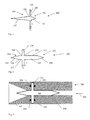
- Fig. 1 11 shows a side view of an adapter 100.
- the adapter 100 is not only arranged to separate two spaces, eg, an interior and an exterior of a container, but the adapter 100 is also configured to cause little influence of an electromagnetic wave. Since a slight influence of an electromagnetic wave, in particular a high-frequency electromagnetic wave (RF wave) can be achieved, when the matching device 100 has conical or conical ends, the matching device 100 is also referred to as adapter cone 100.
- RF wave high-frequency electromagnetic wave
- the adjusting device 100 may be a rotationally symmetrical rotary part, which is made of PTFE, for example.
- the axis of rotation may be parallel to the longitudinal axis of the adapter 100 in the case of rotational symmetry.
- the adapter 100 further includes a first tapered end 103 and a second tapered end 104. With their bases, i. with their base surfaces, the two conical ends are arranged on the circular collar 101, on the annular expansion 101 or on the circular flange 101. Where in the case of one-piece production, the bases are no longer recognizable.
- the first conical end 103 and the second conical end 104 form, for example, a closure body.
- the widening 101 is an RF choke 101 and is used to attach a seal in the axial direction.
- a seal By means of the axial seal may be a small sealing effect, which may achieve the widening 101 alone, increase.
- the widening 101 essentially blocks a flow of a fluid along the mantle surface 102, 107 of the two conical ends 103, 104.
- a seal is placed in the axial direction on the expansion 101.
- a seal is provided for sealing at the widening 101, such as an O-ring. In Fig. 1 However, the seal is not shown.
- the widening 101 may increase the area to which a gasket can be attached.
- the gasket may come to lie in an installed state between the expansion and a waveguide or the outer conductor of a waveguide. If the seal is pinched by pressure between the expansion 101 and the waveguide, the sealing effect of the seal can be increased.
- the bases of the two conical ends 103, 104 directly adjoin the widening 101.
- the widening is arranged at right angles to the longitudinal axis of the adapter 100.
- results between the conical end 103, 104 and the expansion 101 each have an angle 105, 106, which is greater than 90 °, ie an obtuse angle.
- a sealing ring for example an O-ring, can be fixedly arranged on the collar 101.
- the widening 101 has a distance w or a length w from the outermost lateral surface of the base of the first conical end 103 of more than ⁇ / 2.
- ⁇ is the wavelength of an electromagnetic wave, which likewise, like the fluid, propagates substantially parallel to the axis of symmetry of the matching device.
- the length w can be any multiple of ⁇ / 2.
- the expansion w of the widening can be referred to as width w or length w. In a direction perpendicular to the longitudinal axis of the adapter 100 like the Widening 101 have the length w. Viewed in the longitudinal direction, the widening 101 may have the width w.
- the width w, the length w or the radius w may be selected such that an apparent HF short circuit which is located at the end of the widening 101, which end is farthest from the longitudinal axis of the adjusting device, becomes apparent Short circuit on the outermost lateral surface of the first conical end 103 or generally on the outermost lateral surface of the closure body is transformed.
- a substantially interference-free propagation of an electromagnetic wave can take place, since the HF choke 101 is virtually invisible to the RF in the corresponding frequency band or at a corresponding center frequency, and therefore essentially no, or at least only slight disturbances due to reflections caused.
- the thickness h of the widening 101 in the axial direction relative to the longitudinal axis of the fitting device is ⁇ / 4 or a value very close to ⁇ / 4 ( ⁇ / 4 plus / minus 10%, ie from 0.9 ⁇ / 4 to 1.1 ⁇ / 4).
- Other values, such as B. 3 ⁇ / 4 or other values are conceivable, but then certain disturbances in the form of reflections and / or attenuation can occur.
- the shape of the widening 101 may be annular, rectangular, polygonal or oval.
- first tapered end 103 or the second tapered end 104 may be pyramidal.
- the base surface of the first tapered end and the second tapered end may conform to the shape of the rectangular waveguide. The dimensions may depend on the wavelength ⁇ .
- the base surface or the closure body 102, 107 may be round.
- the adapter 100 is shaped such that the adapter 100 does not substantially interfere with RF technology and the antenna system can still be efficiently sealed.
- the S parameter S 11 that is, the reflection loss or the return loss may be small in value.
- the distance of the tip of the first tapered end 103 to the base of the first tapered end 103 is less than the distance of the tip of the second tapered end 104 to the base of the second tapered end 104.
- the angle at the tip of the first tapered end 103 is more obtuse as the angle at the tip of the second tapered end 104.
- the matching device 100 enables even a W-band antenna system to be efficiently sealed without significantly affecting the HF.
- the widening 101 is not limited to ⁇ / 2 but may be greater than ⁇ / 2.
- the widening may for example also be a multiple of ⁇ / 2.
- a further adjusting device 200 can be seen.
- the adapter cone 200 also has a first conical end 203 and a second conical end 204.
- the flange 201, the expansion 201, the shoulder 201 or the collar 201 can be seen, which is arranged between the two conical ends 203, 204.
- Fig. 2 In contrast to Fig. 1 is the Fig. 2 additionally to be seen that between the flange 201 and the first conical end 201 of the first cylinder portion 207 of the closure body is arranged. In addition, it can be seen that between the second conical end 204 and the flange 201 of the second cylinder portion 208 of the closure body is arranged. In other words, this means that the closure body in each case has a cylinder region 207, 208 and a conical end 201, 204.
- the closure body is designed as a solid body.
- a first right angle 205 can be seen between the lateral surface 211 of the first cylinder region 207 and the widening 201.
- a first right angle 205 can be seen between the lateral surface 212 of the second cylinder region 208 and the widening 201.
- the second right angle 206 can be seen between the lateral surface 212 of the second cylinder region 208 and the widening 201.
- the widening 201 extends over the length w or the width w, which is ⁇ / 2 or a multiple of ⁇ / 2.
- the shape 211 of the lateral surface of the first cylinder region 207 and the shape of the lateral surface 212 of the second cylinder region 208 may be adapted to the shape of a waveguide. Furthermore, the shape of the lateral surface 211 of the first cylinder region 207 and the shape of the lateral surface 212 of the second cylinder region 208 are adapted to the shape of the base of the first conical end 203. Thus, a substantially continuous transition between the lateral surface 209 of the first conical end 203 and the lateral surface of the first cylinder portion 207, and between the lateral surface 210 of the second conical end 204 and the lateral surface of the second cylinder portion 208 is possible.
- the first cylinder portion 207 and the second cylinder portion 208 may each be a circular cylinder or a rectangular cylinder independently of each other.
- the first cylinder area 207 is longer than the second cylinder area 208.
- Both the adapter device 100 and the adapter device 200 can be constructed in one piece or in several parts.
- the adaptation device 100, 200 is produced, for example, as a turned part or injection-molded part.
- the two halves are separated or cut apart along a vertical parting plane to the longitudinal axis of the adapter 100, 200.
- the parting plane can extend through the widening 101, 201, lie between the widening 101, 201 and the first conical end 103, 203, or lie between the widening 101, 201 and the second conical end 103, 203.
- FIG. 4 shows a longitudinal section through an antenna arrangement 302 with the matching device 200 Fig. 2 ,
- the Fig. 3 shows how the fitting cone 200 is incorporated in an antenna system 302.
- the antenna system 302 or the antenna arrangement 302 has the waveguide 300 and the antenna horn 301.
- the antenna horn 301 has a funnel-shaped widening.
- the antenna horn 301 may have a rectangular or round cross-section.
- the waveguide 300, in particular the outer conductor 300 of the waveguide, the antenna horn 301 and the matching device 200 may be rotationally symmetrical.
- the associated symmetry axes run parallel to the longitudinal axis of the matching device 200 and essentially determine the propagation direction of an electromagnetic wave.
- the direction of propagation may be understood to mean the direction of a wave directed toward a good, wherein the distance of the product is to be measured. In the direction opposite to this direction may be a reflected wave.
- the propagation direction is in Fig. 3 indicated by the arrow 305.
- Both the antenna horn 301 and the waveguide 300 are filled with air.
- any material, in particular any desired dielectric, can be used for filling.
- the adapter device 200 essentially blocks the connection between the antenna horn 301 and the waveguide 300 for the passage of a fluid, in particular by means of the widening 201 and by means of the closure body.
- the first conical end 203 protrudes into the waveguide 300 and the second conical end 204 protrudes into the antenna horn 301.
- the shape of the matching device 200 is adapted such that the arrangement of the matching device 200 in the antenna arrangement 302 produces the least possible reflection, ie the S 11 value or S 11 wave parameter is as small as possible, while the width w of the collar 201 or the width w of the collar measured from the lateral surface 211, 212 of the closure body is a multiple of ⁇ / 2.
- An example of a value for the S parameter S11 is -20dB. At this value, essentially only one-hundredth of the power fed in may be reflected back.
- the collar width w i. the radial extent of the expansion 101, 201 may be greater than ⁇ / 2.
- the collar width w can also be a multiple of ⁇ / 2.
- the widening 201, 101 may also be referred to as radial widening.
- the radial expansion has a thickness h.
- the thickness h of the radial expansion may be in the range of ⁇ / 4.
- the thickness of the collar 101, 201 may be thicker than ⁇ / 4, it being important to ensure that the S 11 parameter is still below a predefinable maximum value.
- the sealing ring 303, 304 or the sealing rings 303, 304 can be mounted both in front of and behind the collar 101, 102, the widening 101, 102 or the HF choke 101, 102. It is also conceivable to install in front of and behind the widening 201 a single seal 303, 304 or several seals 303, 304 s.
- an O-ring may also be disposed in a notch in one of the tapered ends 102, 107, 209, 210, on the first cylinder portion 207 in a notch, and / or on the second cylinder portion 208 in a notch.
- a notch may be configured, for example, as a groove, constriction or recess.
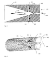
- the Fig. 4 shows a longitudinal section through an antenna assembly 402 with the adapter 100 or the adapter cone 100 of the Fig. 1 ,
- a wave propagation direction or the direction of the longitudinal axis is indicated by arrow 404.
- the matching device 100 is disposed between the waveguide 400 and the antenna horn 401.
- the longer second conical end 107 protrudes into the funnel-shaped antenna horn 401, while the shorter first conical end 102 protrudes into the waveguide 400.
- the waveguide 400 and the antenna horn 401 are filled with air, but may be filled with any dielectric.
- a gap 405 may be formed between the waveguide 400, in particular the outer conductor 400 of the waveguide and the antenna horn 401. This gap may facilitate assembly and disassembly of the antenna assembly 402 for installation and removal of the adapter 100. However, in a built-in state, the gap 405 may be so small that substantially a short circuit for an electromagnetic wave of a predeterminable frequency may occur.
- the antenna arrangement 302, 402 is arranged in a built-in state on a container outer wall such that the funnel-shaped antenna horn 401 protrudes into the container interior and the waveguide 300, 400 protrudes from the container, so that a further conductor, in particular a further waveguide, on the waveguide 300, 400 can be connected.
- This further conductor may e.g. the wave supply to the waveguide or serve as an RF coupling
- the RF signal of the microwave module is coupled.
- the waveguide is excited in the fundamental mode, so that only one mode is capable of propagation. For circular waveguides, this is the H 11 mode.
- the cross-sectional area of the first cylinder area 207 or of the second cylinder area 208 or the base area or the base of the first conical area End 103, 203 or the base of the second conical end 104, 204 depends on the dimensions of the waveguide 300, 400.
- the cross-sectional area or the base of the wavelength ⁇ which is to be transmitted in the waveguide 300, 400.
- Fig. 5 shows a perspective view of the antenna assembly Fig. 4 according to an exemplary embodiment of the present invention. Therein, the lateral surface of the funnel-shaped antenna horn 401 can be seen, which forms the continuation of the waveguide 400.
- the antenna assembly 402 may be considered as a waveguide.
- the waveguide may include an antenna horn 401 and a waveguide 400.
- the Fig. 5 is also the axial arrangement of the sealing ring 403 at the widening 101 refer to.
- the coordinate system 500 shows that the longitudinal axis of the adapter 100 extends through the tips of the adapter in the z-direction.
- the z-axis also denotes the direction of the longitudinal axis of the adjusting device.
- Fig. 6 shows a longitudinal section through a further antenna arrangement 602 with the matching device 200 from Fig. 2 , Similar to in Fig. 3
- the matching device 200 is shown disposed in the waveguide 300 and the antenna horn 301.
- the first sealing ring 600 and the second sealing ring 601 are arranged on the same side.
- a rectangular recess or groove is provided in the outer conductor 300 of the waveguide, which has smaller dimensions than the cord thickness of the first sealing ring 600, so that the first sealing ring 600 is compressed.
- a second rectangular recess formed in the waveguide 300 which receives the second sealing ring.
- Antenna systems or antenna assemblies 302, 402 should be configured to provide good impedance matching of electrical junctions, such as the junction between a connection line or RF feed and a waveguide 300 400, between a waveguide 300, 400 and an antenna 301, 401, or between antenna 301 , 401 and air to obtain the least possible interference reflections.
- an antenna assembly 302, 402 should be configured to allow substantially complete sealing of a container to the outside.
- Arrangements with radial sealing rings on the adapter cone 100, 200 of the antenna coupling can have power losses in these frequency ranges.
- the power losses can be caused by the dimensions of the mechanical parts, such as waveguide 300, 400, adapter cone 100, 200, etc. becoming smaller and smaller as the frequency increases.
- a sealing ring (O-ring) 304, 303, 403 should be set up so that it has a certain cord thickness and thus ensures a secure seal.
- the size of a sealing ring and thus the size of the puncture remains unchanged.
- the groove or groove, in which a sealing ring 304, 303, 403 is arranged in relation to the diameter of the cylinder 207, 208 of the adapter cone 100, 200 already so large that the puncture the propagation of the electromagnetic wave can disturb.
- the echo amplitude of an electromagnetic wave can be damped.
- a waveguide 300, 400 with an adapter cone 100, 200, in which the sealing ring 303, 304, 600, 601 is axially mounted, can reduce an attenuation of the echo amplitude or the "ringing".
- the O-ring with its partially negative electrical properties is located substantially outside the direct signal path of an electromagnetic wave.
- a thickening 101, 201 or widening 101, 201 on the adapter cone 100, 200 can be used.
- the thickness h of this broadening should be in the range of ⁇ / 4.
- Fig. 7 5 shows an antenna arrangement 706 in which the matching element 701, in particular the collar 708 of the matching element 701, or a seal 703, which is arranged on the collar 708 of the matching element, is pressed against the flange 707 of the antenna horn 700.
- the adapter cone 701 has a rectangular and a pointed end, wherein the rectangular end is adapted to receive the RF coupling (high frequency coupling) 705.
- the adapter cone 701 may be made of any material having dielectric properties.
- the sealing ring 703, which is arranged in the annular groove 702, may consist of all commonly used for sealing rings materials.
- elastomers may be used to make the sealing rings 303, 304, 403, 600, 601, 703.
- Elastomers are stretchable materials.
- metal or FEP (perfluoroethylene copolymers) sheathed elastomers can be used.
- the recess 702 or the groove 702 for the sealing ring 703 is inserted into the waveguide so that the O-ring 703 used approximately in the middle of the thickening 708, in particular in the middle of the length w of the thickening 708, located inside and on the waveguide 704 is applied, so that the sealing ring 703 seals to the rear (ie in the direction of the RF coupling 705).
- the O-ring 703 is directly pressed to the flange 707 of the antenna horn 700.
- the Fig. 8 1 shows an antenna arrangement 801 in which a disk 800 is arranged between the waveguide 704 and the antenna horn 700.
- a disk 800 is arranged between the waveguide 704 and the antenna horn 700.
- the disc 800 available.
- the disc 800 is disposed between the collar 708 of the matching element 701 and the flange 707 of the antenna horn 700.
- the O-ring 703 is crimped with the aid of an additional disk 800, for example a metal ring 800, which disk 800 is secured to the waveguide 704 with countersunk screws.
- the O-ring 703 is pressed by a pressure applied by the expansion 708 into the groove 702 of the waveguide 704.
- the pressure of the widening 708 is generated by a disc 800 which is secured by countersunk screws (not shown in Figs Fig. 8 ) is pressed against the widening 708.
- the adapter cone 701 is secured against falling out.
- the risk can be reduced that the adapter cone 701 falls out of the waveguide 704.
Landscapes
- Physics & Mathematics (AREA)
- Electromagnetism (AREA)
- Thermal Sciences (AREA)
- Fluid Mechanics (AREA)
- General Physics & Mathematics (AREA)
- Waveguide Aerials (AREA)
- Aerials With Secondary Devices (AREA)
- Support Of Aerials (AREA)
- Details Of Aerials (AREA)
Priority Applications (4)
| Application Number | Priority Date | Filing Date | Title |
|---|---|---|---|
| HUE08155923A HUE041908T2 (hu) | 2008-05-08 | 2008-05-08 | Illesztõegység alkalmazása, mérõkészülék az illesztõegységgel és eljárás hullámvezetõ üzemeltetésére |
| EP08155923.9A EP2116820B1 (fr) | 2008-05-08 | 2008-05-08 | Usage d'un dispositif d'adaptation d'impédance, appareil de mesure avec dispositif d'adaptation d'impédance et procédé pour opérer un guide d'ondes |
| US12/431,985 US20100109963A1 (en) | 2008-05-08 | 2009-04-29 | Sealing an Antenna System |
| CN200910140422.8A CN101577359B (zh) | 2008-05-08 | 2009-05-08 | 密封天线系统 |
Applications Claiming Priority (1)
| Application Number | Priority Date | Filing Date | Title |
|---|---|---|---|
| EP08155923.9A EP2116820B1 (fr) | 2008-05-08 | 2008-05-08 | Usage d'un dispositif d'adaptation d'impédance, appareil de mesure avec dispositif d'adaptation d'impédance et procédé pour opérer un guide d'ondes |
Publications (2)
| Publication Number | Publication Date |
|---|---|
| EP2116820A1 true EP2116820A1 (fr) | 2009-11-11 |
| EP2116820B1 EP2116820B1 (fr) | 2018-09-05 |
Family
ID=39884624
Family Applications (1)
| Application Number | Title | Priority Date | Filing Date |
|---|---|---|---|
| EP08155923.9A Not-in-force EP2116820B1 (fr) | 2008-05-08 | 2008-05-08 | Usage d'un dispositif d'adaptation d'impédance, appareil de mesure avec dispositif d'adaptation d'impédance et procédé pour opérer un guide d'ondes |
Country Status (4)
| Country | Link |
|---|---|
| US (1) | US20100109963A1 (fr) |
| EP (1) | EP2116820B1 (fr) |
| CN (1) | CN101577359B (fr) |
| HU (1) | HUE041908T2 (fr) |
Cited By (1)
| Publication number | Priority date | Publication date | Assignee | Title |
|---|---|---|---|---|
| US10539448B2 (en) | 2016-10-21 | 2020-01-21 | Rosemount Tank Radar Ab | Radar level gauge with high temperature, high pressure (HTHP) process seal |
Families Citing this family (13)
| Publication number | Priority date | Publication date | Assignee | Title |
|---|---|---|---|---|
| US9291492B2 (en) | 2013-03-12 | 2016-03-22 | Rosemount Tank Radar Ab | Tank feed through structure for a radar level gauge |
| US9212941B2 (en) * | 2013-03-12 | 2015-12-15 | Rosemount Tank Radar Ab | High temperature, high pressure (HTHP) radar level gauge |
| US9329072B2 (en) * | 2013-12-06 | 2016-05-03 | Honeywell International Inc. | Receiver with programmable gain for UWB radar |
| US9329074B2 (en) * | 2013-12-06 | 2016-05-03 | Honeywell International Inc. | Multi-mode pulsed radar providing automatic transmit pulse signal control |
| US9329073B2 (en) * | 2013-12-06 | 2016-05-03 | Honeywell International Inc. | Adaptive radar system with mutliple waveforms |
| HUE039704T2 (hu) | 2014-04-08 | 2019-01-28 | Grieshaber Vega Kg | Védõeszköz hullámvezetõhöz és eljárás védõeszköz gyártására |
| CN105609951A (zh) * | 2014-11-24 | 2016-05-25 | 中国航空工业集团公司雷华电子技术研究所 | 圆波导介质隔离轴结构 |
| EP3168579A1 (fr) * | 2015-11-13 | 2017-05-17 | VEGA Grieshaber KG | Antenne a cornet |
| EP3483569B1 (fr) * | 2017-11-14 | 2021-08-25 | VEGA Grieshaber KG | Appareil de mesure de niveau de remplissage avec séparation galvanique dans le guide d'ondes |
| KR101961672B1 (ko) * | 2018-06-11 | 2019-03-26 | 두온시스템(주) | 레이더 레벨 측정 장치 |
| US10809114B2 (en) * | 2018-06-27 | 2020-10-20 | Rosemount Tank Radar Ab | Sealing dielectric filling member with mechanically reinforced element |
| CN113708036B (zh) * | 2020-05-21 | 2022-09-23 | 华为技术有限公司 | 一种信号传输组件 |
| US12609454B1 (en) * | 2024-05-24 | 2026-04-21 | Caes Systems Llc | Linear horn antenna with conical collar |
Citations (2)
| Publication number | Priority date | Publication date | Assignee | Title |
|---|---|---|---|---|
| US5872494A (en) * | 1997-06-27 | 1999-02-16 | Rosemount Inc. | Level gage waveguide process seal having wavelength-based dimensions |
| EP1643222A1 (fr) | 2004-09-30 | 2006-04-05 | Siemens Milltronics Process Instruments Inc. | Structure d'antenne utilisée dans un appareil de mesure de niveau |
Family Cites Families (5)
| Publication number | Priority date | Publication date | Assignee | Title |
|---|---|---|---|---|
| US3001160A (en) * | 1959-07-20 | 1961-09-19 | John E Trousdale | High pressure waveguide window |
| US3406979A (en) * | 1965-02-19 | 1968-10-22 | California Fruit Concentrates | Reinforced o-ring |
| US5305237A (en) * | 1991-07-12 | 1994-04-19 | Union Tank Car Company | Method and apparatus for monitoring a flowable material in a transportable vessel |
| SE0200792D0 (sv) * | 2002-03-18 | 2002-03-18 | Saab Marine Electronics | Hornantenn |
| DE602005020434D1 (de) * | 2005-06-13 | 2010-05-20 | Siemens Milltronics Proc Instr | Hornantenne mit Verbundwerkstoffstrahler |
-
2008
- 2008-05-08 HU HUE08155923A patent/HUE041908T2/hu unknown
- 2008-05-08 EP EP08155923.9A patent/EP2116820B1/fr not_active Not-in-force
-
2009
- 2009-04-29 US US12/431,985 patent/US20100109963A1/en not_active Abandoned
- 2009-05-08 CN CN200910140422.8A patent/CN101577359B/zh not_active Expired - Fee Related
Patent Citations (2)
| Publication number | Priority date | Publication date | Assignee | Title |
|---|---|---|---|---|
| US5872494A (en) * | 1997-06-27 | 1999-02-16 | Rosemount Inc. | Level gage waveguide process seal having wavelength-based dimensions |
| EP1643222A1 (fr) | 2004-09-30 | 2006-04-05 | Siemens Milltronics Process Instruments Inc. | Structure d'antenne utilisée dans un appareil de mesure de niveau |
Cited By (1)
| Publication number | Priority date | Publication date | Assignee | Title |
|---|---|---|---|---|
| US10539448B2 (en) | 2016-10-21 | 2020-01-21 | Rosemount Tank Radar Ab | Radar level gauge with high temperature, high pressure (HTHP) process seal |
Also Published As
| Publication number | Publication date |
|---|---|
| EP2116820B1 (fr) | 2018-09-05 |
| HUE041908T2 (hu) | 2019-06-28 |
| US20100109963A1 (en) | 2010-05-06 |
| CN101577359A (zh) | 2009-11-11 |
| CN101577359B (zh) | 2015-08-12 |
Similar Documents
| Publication | Publication Date | Title |
|---|---|---|
| EP2116820B1 (fr) | Usage d'un dispositif d'adaptation d'impédance, appareil de mesure avec dispositif d'adaptation d'impédance et procédé pour opérer un guide d'ondes | |
| DE19641036C2 (de) | Mit Mikrowellen arbeitendes Füllstandsmeßgerät | |
| EP2592693B1 (fr) | Antenne diélectrique | |
| EP0947812A1 (fr) | Capteur du niveau à microondes | |
| EP3563121B1 (fr) | Assemblage de mesure permettant d'analyser les propriétés d'un milieu fluide par des micro-ondes | |
| WO2014006148A1 (fr) | Couplage étanche au gaz d'un guide d'onde, moudule haute fréquence, radar de niveau de remplissage et utilisation | |
| EP3483569B1 (fr) | Appareil de mesure de niveau de remplissage avec séparation galvanique dans le guide d'ondes | |
| DE102016106747B4 (de) | Wellenleiter-Kopplungsvorrichtung und Positionssensorvorrichtung für einen Hydraulikzylinder, Hydraulikzylinder, sowie Verfahren zum Betreiben einer Wellenleiter-Kopplungsvorrichtung | |
| DE2746376C2 (de) | Koppelvorrichtung zwischen einer Koaxialleitung und einem Hohlleiter | |
| EP3084369B1 (fr) | Appareil de mesure de niveau à radar | |
| DE102012112318B4 (de) | Vorrichtung zum Ausrichten und Zentrieren eines Oberflächenwellenleiters eines Feldgerätes | |
| EP3473988B1 (fr) | Dispositif de mesure d'un niveau de remplissage doté de guides d'ondes d'émission et de réception tubulaires et flexibles | |
| EP0971213B1 (fr) | Appareil à micro-ondes de mesure de niveau de contenu avec qualité de signal améliorée | |
| EP2000823B1 (fr) | Couvercle d'un cylindre fluidique avec un dispositif de mesure destiné à la saisie de la position de pistons dans le cylindre fluidique doté d'une sonde de couplage à micro-ondes | |
| DE102011084592A1 (de) | Kombination eines Radar- und Antennenkopfes | |
| EP3813188B1 (fr) | Agencement de guide d'ondes et antenne | |
| EP4586396A1 (fr) | Capteur radar et séparateur de guide d'ondes | |
| DE102015111289B4 (de) | Antennen-Einheit für ein Radar-basiertes Füllstandsmessgerät und Füllstandsmessgerät | |
| DE102015006739A1 (de) | Hochfrequenzleitersystem mit leitungsgebundener HF-Durchführung | |
| DE102014019716A1 (de) | Wellenleiterübergangsvorrichtung und Verfahren zum Betreiben einer Wellenleiterübergangsvorrichtung | |
| DE202009001395U1 (de) | Vorrichtung zur Einkopplung von Hochfrequenzsignalen für Frequenzen größer als 1 GHz in einen elektrisch leitenden Hohlleiter | |
| DE112004000368T5 (de) | Verfahren und Vorrichtung für ein Radarfüllstandsmesssystem | |
| EP3001515B1 (fr) | Boitier hf avec connecteur a fiches hf coaxial | |
| DE102014112058B4 (de) | Wellenleiterübergangsvorrichtung und Verfahren zum Betreiben einer Wellenleiterübergangsvorrichtung | |
| EP2683023B1 (fr) | Couplage de guide d'ondes, module de haute fréquence, radar de niveau de remplissage et utilisation |
Legal Events
| Date | Code | Title | Description |
|---|---|---|---|
| PUAI | Public reference made under article 153(3) epc to a published international application that has entered the european phase |
Free format text: ORIGINAL CODE: 0009012 |
|
| AK | Designated contracting states |
Kind code of ref document: A1 Designated state(s): AT BE BG CH CY CZ DE DK EE ES FI FR GB GR HR HU IE IS IT LI LT LU LV MC MT NL NO PL PT RO SE SI SK TR |
|
| AX | Request for extension of the european patent |
Extension state: AL BA MK RS |
|
| 17P | Request for examination filed |
Effective date: 20100318 |
|
| 17Q | First examination report despatched |
Effective date: 20100413 |
|
| AKX | Designation fees paid |
Designated state(s): AT BE BG CH CY CZ DE DK EE ES FI FR GB GR HR HU IE IS IT LI LT LU LV MC MT NL NO PL PT RO SE SI SK TR |
|
| STAA | Information on the status of an ep patent application or granted ep patent |
Free format text: STATUS: EXAMINATION IS IN PROGRESS |
|
| GRAP | Despatch of communication of intention to grant a patent |
Free format text: ORIGINAL CODE: EPIDOSNIGR1 |
|
| STAA | Information on the status of an ep patent application or granted ep patent |
Free format text: STATUS: GRANT OF PATENT IS INTENDED |
|
| INTG | Intention to grant announced |
Effective date: 20180413 |
|
| GRAS | Grant fee paid |
Free format text: ORIGINAL CODE: EPIDOSNIGR3 |
|
| GRAA | (expected) grant |
Free format text: ORIGINAL CODE: 0009210 |
|
| STAA | Information on the status of an ep patent application or granted ep patent |
Free format text: STATUS: THE PATENT HAS BEEN GRANTED |
|
| AK | Designated contracting states |
Kind code of ref document: B1 Designated state(s): AT BE BG CH CY CZ DE DK EE ES FI FR GB GR HR HU IE IS IT LI LT LU LV MC MT NL NO PL PT RO SE SI SK TR |
|
| REG | Reference to a national code |
Ref country code: GB Ref legal event code: FG4D Free format text: NOT ENGLISH |
|
| REG | Reference to a national code |
Ref country code: CH Ref legal event code: EP |
|
| REG | Reference to a national code |
Ref country code: AT Ref legal event code: REF Ref document number: 1038361 Country of ref document: AT Kind code of ref document: T Effective date: 20180915 |
|
| REG | Reference to a national code |
Ref country code: IE Ref legal event code: FG4D Free format text: LANGUAGE OF EP DOCUMENT: GERMAN |
|
| REG | Reference to a national code |
Ref country code: DE Ref legal event code: R096 Ref document number: 502008016313 Country of ref document: DE |
|
| REG | Reference to a national code |
Ref country code: NL Ref legal event code: FP |
|
| REG | Reference to a national code |
Ref country code: SE Ref legal event code: TRGR |
|
| REG | Reference to a national code |
Ref country code: LT Ref legal event code: MG4D |
|
| PG25 | Lapsed in a contracting state [announced via postgrant information from national office to epo] |
Ref country code: LT Free format text: LAPSE BECAUSE OF FAILURE TO SUBMIT A TRANSLATION OF THE DESCRIPTION OR TO PAY THE FEE WITHIN THE PRESCRIBED TIME-LIMIT Effective date: 20180905 Ref country code: NO Free format text: LAPSE BECAUSE OF FAILURE TO SUBMIT A TRANSLATION OF THE DESCRIPTION OR TO PAY THE FEE WITHIN THE PRESCRIBED TIME-LIMIT Effective date: 20181205 Ref country code: GR Free format text: LAPSE BECAUSE OF FAILURE TO SUBMIT A TRANSLATION OF THE DESCRIPTION OR TO PAY THE FEE WITHIN THE PRESCRIBED TIME-LIMIT Effective date: 20181206 Ref country code: FI Free format text: LAPSE BECAUSE OF FAILURE TO SUBMIT A TRANSLATION OF THE DESCRIPTION OR TO PAY THE FEE WITHIN THE PRESCRIBED TIME-LIMIT Effective date: 20180905 Ref country code: BG Free format text: LAPSE BECAUSE OF FAILURE TO SUBMIT A TRANSLATION OF THE DESCRIPTION OR TO PAY THE FEE WITHIN THE PRESCRIBED TIME-LIMIT Effective date: 20181205 |
|
| PG25 | Lapsed in a contracting state [announced via postgrant information from national office to epo] |
Ref country code: LV Free format text: LAPSE BECAUSE OF FAILURE TO SUBMIT A TRANSLATION OF THE DESCRIPTION OR TO PAY THE FEE WITHIN THE PRESCRIBED TIME-LIMIT Effective date: 20180905 Ref country code: ES Free format text: LAPSE BECAUSE OF FAILURE TO SUBMIT A TRANSLATION OF THE DESCRIPTION OR TO PAY THE FEE WITHIN THE PRESCRIBED TIME-LIMIT Effective date: 20180905 Ref country code: HR Free format text: LAPSE BECAUSE OF FAILURE TO SUBMIT A TRANSLATION OF THE DESCRIPTION OR TO PAY THE FEE WITHIN THE PRESCRIBED TIME-LIMIT Effective date: 20180905 |
|
| PG25 | Lapsed in a contracting state [announced via postgrant information from national office to epo] |
Ref country code: IT Free format text: LAPSE BECAUSE OF FAILURE TO SUBMIT A TRANSLATION OF THE DESCRIPTION OR TO PAY THE FEE WITHIN THE PRESCRIBED TIME-LIMIT Effective date: 20180905 Ref country code: EE Free format text: LAPSE BECAUSE OF FAILURE TO SUBMIT A TRANSLATION OF THE DESCRIPTION OR TO PAY THE FEE WITHIN THE PRESCRIBED TIME-LIMIT Effective date: 20180905 Ref country code: CZ Free format text: LAPSE BECAUSE OF FAILURE TO SUBMIT A TRANSLATION OF THE DESCRIPTION OR TO PAY THE FEE WITHIN THE PRESCRIBED TIME-LIMIT Effective date: 20180905 Ref country code: RO Free format text: LAPSE BECAUSE OF FAILURE TO SUBMIT A TRANSLATION OF THE DESCRIPTION OR TO PAY THE FEE WITHIN THE PRESCRIBED TIME-LIMIT Effective date: 20180905 Ref country code: IS Free format text: LAPSE BECAUSE OF FAILURE TO SUBMIT A TRANSLATION OF THE DESCRIPTION OR TO PAY THE FEE WITHIN THE PRESCRIBED TIME-LIMIT Effective date: 20190105 Ref country code: PL Free format text: LAPSE BECAUSE OF FAILURE TO SUBMIT A TRANSLATION OF THE DESCRIPTION OR TO PAY THE FEE WITHIN THE PRESCRIBED TIME-LIMIT Effective date: 20180905 |
|
| PG25 | Lapsed in a contracting state [announced via postgrant information from national office to epo] |
Ref country code: SK Free format text: LAPSE BECAUSE OF FAILURE TO SUBMIT A TRANSLATION OF THE DESCRIPTION OR TO PAY THE FEE WITHIN THE PRESCRIBED TIME-LIMIT Effective date: 20180905 Ref country code: PT Free format text: LAPSE BECAUSE OF FAILURE TO SUBMIT A TRANSLATION OF THE DESCRIPTION OR TO PAY THE FEE WITHIN THE PRESCRIBED TIME-LIMIT Effective date: 20190105 |
|
| REG | Reference to a national code |
Ref country code: DE Ref legal event code: R097 Ref document number: 502008016313 Country of ref document: DE |
|
| REG | Reference to a national code |
Ref country code: HU Ref legal event code: AG4A Ref document number: E041908 Country of ref document: HU |
|
| PLBE | No opposition filed within time limit |
Free format text: ORIGINAL CODE: 0009261 |
|
| STAA | Information on the status of an ep patent application or granted ep patent |
Free format text: STATUS: NO OPPOSITION FILED WITHIN TIME LIMIT |
|
| PG25 | Lapsed in a contracting state [announced via postgrant information from national office to epo] |
Ref country code: DK Free format text: LAPSE BECAUSE OF FAILURE TO SUBMIT A TRANSLATION OF THE DESCRIPTION OR TO PAY THE FEE WITHIN THE PRESCRIBED TIME-LIMIT Effective date: 20180905 |
|
| 26N | No opposition filed |
Effective date: 20190606 |
|
| PG25 | Lapsed in a contracting state [announced via postgrant information from national office to epo] |
Ref country code: SI Free format text: LAPSE BECAUSE OF FAILURE TO SUBMIT A TRANSLATION OF THE DESCRIPTION OR TO PAY THE FEE WITHIN THE PRESCRIBED TIME-LIMIT Effective date: 20180905 |
|
| REG | Reference to a national code |
Ref country code: CH Ref legal event code: PL |
|
| PG25 | Lapsed in a contracting state [announced via postgrant information from national office to epo] |
Ref country code: CH Free format text: LAPSE BECAUSE OF NON-PAYMENT OF DUE FEES Effective date: 20190531 Ref country code: LI Free format text: LAPSE BECAUSE OF NON-PAYMENT OF DUE FEES Effective date: 20190531 Ref country code: MC Free format text: LAPSE BECAUSE OF FAILURE TO SUBMIT A TRANSLATION OF THE DESCRIPTION OR TO PAY THE FEE WITHIN THE PRESCRIBED TIME-LIMIT Effective date: 20180905 |
|
| REG | Reference to a national code |
Ref country code: BE Ref legal event code: MM Effective date: 20190531 |
|
| PG25 | Lapsed in a contracting state [announced via postgrant information from national office to epo] |
Ref country code: LU Free format text: LAPSE BECAUSE OF NON-PAYMENT OF DUE FEES Effective date: 20190508 |
|
| PG25 | Lapsed in a contracting state [announced via postgrant information from national office to epo] |
Ref country code: TR Free format text: LAPSE BECAUSE OF FAILURE TO SUBMIT A TRANSLATION OF THE DESCRIPTION OR TO PAY THE FEE WITHIN THE PRESCRIBED TIME-LIMIT Effective date: 20180905 |
|
| PG25 | Lapsed in a contracting state [announced via postgrant information from national office to epo] |
Ref country code: IE Free format text: LAPSE BECAUSE OF NON-PAYMENT OF DUE FEES Effective date: 20190508 |
|
| PG25 | Lapsed in a contracting state [announced via postgrant information from national office to epo] |
Ref country code: BE Free format text: LAPSE BECAUSE OF NON-PAYMENT OF DUE FEES Effective date: 20190531 |
|
| REG | Reference to a national code |
Ref country code: AT Ref legal event code: MM01 Ref document number: 1038361 Country of ref document: AT Kind code of ref document: T Effective date: 20190508 |
|
| PG25 | Lapsed in a contracting state [announced via postgrant information from national office to epo] |
Ref country code: AT Free format text: LAPSE BECAUSE OF NON-PAYMENT OF DUE FEES Effective date: 20190508 |
|
| PG25 | Lapsed in a contracting state [announced via postgrant information from national office to epo] |
Ref country code: CY Free format text: LAPSE BECAUSE OF FAILURE TO SUBMIT A TRANSLATION OF THE DESCRIPTION OR TO PAY THE FEE WITHIN THE PRESCRIBED TIME-LIMIT Effective date: 20180905 |
|
| PG25 | Lapsed in a contracting state [announced via postgrant information from national office to epo] |
Ref country code: MT Free format text: LAPSE BECAUSE OF FAILURE TO SUBMIT A TRANSLATION OF THE DESCRIPTION OR TO PAY THE FEE WITHIN THE PRESCRIBED TIME-LIMIT Effective date: 20180905 |
|
| PGFP | Annual fee paid to national office [announced via postgrant information from national office to epo] |
Ref country code: FR Payment date: 20210521 Year of fee payment: 14 Ref country code: NL Payment date: 20210519 Year of fee payment: 14 Ref country code: DE Payment date: 20210525 Year of fee payment: 14 |
|
| PGFP | Annual fee paid to national office [announced via postgrant information from national office to epo] |
Ref country code: SE Payment date: 20210521 Year of fee payment: 14 Ref country code: HU Payment date: 20210502 Year of fee payment: 14 Ref country code: GB Payment date: 20210526 Year of fee payment: 14 |
|
| REG | Reference to a national code |
Ref country code: DE Ref legal event code: R119 Ref document number: 502008016313 Country of ref document: DE |
|
| REG | Reference to a national code |
Ref country code: SE Ref legal event code: EUG |
|
| REG | Reference to a national code |
Ref country code: NL Ref legal event code: MM Effective date: 20220601 |
|
| GBPC | Gb: european patent ceased through non-payment of renewal fee |
Effective date: 20220508 |
|
| PG25 | Lapsed in a contracting state [announced via postgrant information from national office to epo] |
Ref country code: SE Free format text: LAPSE BECAUSE OF NON-PAYMENT OF DUE FEES Effective date: 20220509 Ref country code: HU Free format text: LAPSE BECAUSE OF NON-PAYMENT OF DUE FEES Effective date: 20220509 |
|
| PG25 | Lapsed in a contracting state [announced via postgrant information from national office to epo] |
Ref country code: FR Free format text: LAPSE BECAUSE OF NON-PAYMENT OF DUE FEES Effective date: 20220531 |
|
| PG25 | Lapsed in a contracting state [announced via postgrant information from national office to epo] |
Ref country code: GB Free format text: LAPSE BECAUSE OF NON-PAYMENT OF DUE FEES Effective date: 20220508 Ref country code: DE Free format text: LAPSE BECAUSE OF NON-PAYMENT OF DUE FEES Effective date: 20221201 |
|
| P01 | Opt-out of the competence of the unified patent court (upc) registered |
Effective date: 20230523 |
|
| PG25 | Lapsed in a contracting state [announced via postgrant information from national office to epo] |
Ref country code: NL Free format text: LAPSE BECAUSE OF NON-PAYMENT OF DUE FEES Effective date: 20220601 |