EP2116856A2 - Procédé de correction des erreurs lors de la mesure de courant dans un secteur multiphasé - Google Patents
Procédé de correction des erreurs lors de la mesure de courant dans un secteur multiphasé Download PDFInfo
- Publication number
- EP2116856A2 EP2116856A2 EP09100170A EP09100170A EP2116856A2 EP 2116856 A2 EP2116856 A2 EP 2116856A2 EP 09100170 A EP09100170 A EP 09100170A EP 09100170 A EP09100170 A EP 09100170A EP 2116856 A2 EP2116856 A2 EP 2116856A2
- Authority
- EP
- European Patent Office
- Prior art keywords
- current
- phase
- measuring
- discontinuity
- measurement
- Prior art date
- Legal status (The legal status is an assumption and is not a legal conclusion. Google has not performed a legal analysis and makes no representation as to the accuracy of the status listed.)
- Granted
Links
Images

Classifications
-
- G—PHYSICS
- G01—MEASURING; TESTING
- G01R—MEASURING ELECTRIC VARIABLES; MEASURING MAGNETIC VARIABLES
- G01R19/00—Arrangements for measuring currents or voltages or for indicating presence or sign thereof
- G01R19/0092—Measuring current only
-
- H—ELECTRICITY
- H02—GENERATION; CONVERSION OR DISTRIBUTION OF ELECTRIC POWER
- H02M—APPARATUS FOR CONVERSION BETWEEN AC AND AC, BETWEEN AC AND DC, OR BETWEEN DC AND DC, AND FOR USE WITH MAINS OR SIMILAR POWER SUPPLY SYSTEMS; CONVERSION OF DC OR AC INPUT POWER INTO SURGE OUTPUT POWER; CONTROL OR REGULATION THEREOF
- H02M7/00—Conversion of AC power input into DC power output; Conversion of DC power input into AC power output
- H02M7/42—Conversion of DC power input into AC power output without possibility of reversal
- H02M7/44—Conversion of DC power input into AC power output without possibility of reversal by static converters
- H02M7/48—Conversion of DC power input into AC power output without possibility of reversal by static converters using discharge tubes with control electrode or semiconductor devices with control electrode
- H02M7/53—Conversion of DC power input into AC power output without possibility of reversal by static converters using discharge tubes with control electrode or semiconductor devices with control electrode using devices of a triode or transistor type requiring continuous application of a control signal
- H02M7/537—Conversion of DC power input into AC power output without possibility of reversal by static converters using discharge tubes with control electrode or semiconductor devices with control electrode using devices of a triode or transistor type requiring continuous application of a control signal using semiconductor devices only, e.g. single switched pulse inverters
- H02M7/5387—Conversion of DC power input into AC power output without possibility of reversal by static converters using discharge tubes with control electrode or semiconductor devices with control electrode using devices of a triode or transistor type requiring continuous application of a control signal using semiconductor devices only, e.g. single switched pulse inverters in a bridge configuration
- H02M7/53871—Conversion of DC power input into AC power output without possibility of reversal by static converters using discharge tubes with control electrode or semiconductor devices with control electrode using devices of a triode or transistor type requiring continuous application of a control signal using semiconductor devices only, e.g. single switched pulse inverters in a bridge configuration with automatic control of output voltage or current
- H02M7/53875—Conversion of DC power input into AC power output without possibility of reversal by static converters using discharge tubes with control electrode or semiconductor devices with control electrode using devices of a triode or transistor type requiring continuous application of a control signal using semiconductor devices only, e.g. single switched pulse inverters in a bridge configuration with automatic control of output voltage or current with analogue control of three-phase output
- H02M7/53876—Conversion of DC power input into AC power output without possibility of reversal by static converters using discharge tubes with control electrode or semiconductor devices with control electrode using devices of a triode or transistor type requiring continuous application of a control signal using semiconductor devices only, e.g. single switched pulse inverters in a bridge configuration with automatic control of output voltage or current with analogue control of three-phase output based on synthesising a desired voltage vector via the selection of appropriate fundamental voltage vectors, and corresponding dwelling times
-
- G—PHYSICS
- G01—MEASURING; TESTING
- G01R—MEASURING ELECTRIC VARIABLES; MEASURING MAGNETIC VARIABLES
- G01R25/00—Arrangements for measuring phase angle between a voltage and a current or between voltages or currents
-
- H—ELECTRICITY
- H02—GENERATION; CONVERSION OR DISTRIBUTION OF ELECTRIC POWER
- H02M—APPARATUS FOR CONVERSION BETWEEN AC AND AC, BETWEEN AC AND DC, OR BETWEEN DC AND DC, AND FOR USE WITH MAINS OR SIMILAR POWER SUPPLY SYSTEMS; CONVERSION OF DC OR AC INPUT POWER INTO SURGE OUTPUT POWER; CONTROL OR REGULATION THEREOF
- H02M1/00—Details of apparatus for conversion
- H02M1/0003—Details of control, feedback or regulation circuits
- H02M1/0009—Devices or circuits for detecting current in a converter
Definitions
- the invention relates to a method for current measurement of phase currents by means of a measuring circuit in a multi-phase power network, in which at least one controllable switching element, a desired energization of at least one electrical load and acting on the switching element control signals to achieve the desired energization of the consumer, wherein clock patterns
- the control signals are associated with measuring windows for the current measurement and clock patterns for a desired measuring window size and / or position are shifted in time, wherein in the current measurement at least one Stromock exhibiting measuring current waveform is measured, which has at least one error due to the shifted clock pattern, wherein from the measuring current course Current values exhibiting phase current profile is determined, at which the error causes at least one jump.
- phase currents there is often a desire to detect the phase currents. If it is an energization of an electric motor by means of a controllable bridge, which has controllable switching elements in their individual bridge branches, then the electric motor can be energized in the desired manner.
- the switching elements are driven by clock patterns, which are generated for example on the basis of a center-centered pulse width modulation.
- a low-resistance resistor (shunt) is arranged in each phase line.
- shunt low-resistance resistor
- the invention has for its object to enable a very simple and inexpensive power measurement, the error is always corrected correctly.
- the occurrence of the discontinuity is detected, that the jump height of the discontinuity is determined, and that the phase current profile is corrected in dependence on the step height such that the current value corresponding to the step height in the time course following the discontinuity of the step Current values of the measuring current profile at least partially subtracted or added to this at least partially.
- the error is due to reactive current components due to the clock shift of the drive signals, especially when the currents are interacting with each other via an electrical node.
- the method enables automatic and adaptive correction of the inaccuracies in the phase current profile generated by the discontinuities, since each discontinuity is analyzed and its influence on the measurement result is corrected.
- temperature and aging effects, as well as different influences in different operating points of the electrical load are always considered and thus enable a highly accurate current measurement.
- the power network has a rotating phase vector and that a phase current profile is determined from the measurement current profile by directly taking the current values of the phase current profile as a function of a rotation angle of the phase vector from the measurement current profile and / or from current values of at least one measurement current profile be calculated.
- the measurement current course contains either a single phase current profile or a combination of a plurality of phase current characteristics, and it can also be provided that at least part of the phase current profile is calculated.
- the method is preferably used when the power grid is operated by means of pulse width modulation by the switching elements.
- the clock patterns are shifted as a function of the phase position of the phase current profile, which is why the instantaneous content of the measuring current profile can be derived from the angle of rotation which reproduces the phase position of the phase current profile.
- the desired phase current profile can either be taken from the measurement current profile or calculated using electrical equations.
- the occurrence of the discontinuity is detected when, within a defined period of time, an increase and / or a fall in the current values of the phase current profile exceeds or falls below a predetermined threshold value.
- a threshold value maximum increase or maximum waste within a certain period of time. If this threshold value is not met by the phase current profile, then it can be assumed that there is a discontinuity.
- the occurrence of the discontinuity is detected when a deviation of the phase current profile from a calculated and / or estimated expected phase current profile occurs and the deviation exceeds or falls below a threshold value.
- the detection of a jump by means of a maximum increase or decrease from one measurement point to the next can lead to error detections, since the course between the measurement points is not detected. This is the case in particular when the phase vector has high angular velocities and / or high current amplitudes are considered. It therefore makes sense to make an estimate of the next expected current value in the phase current profile in order to be able to evaluate a possible deviation of the detected current value of the phase current profile from the expected current value. This evaluation can again take place via a threshold value.
- the angle of rotation of the phase vector can be divided into regions in which the phase current profile is determined in different ways from the measuring current profile.
- a discontinuity occurs when a transition is made from such a rotation angle range to another rotation angle range, because then a way of determining changes in a next, different way of determining. Due to this change, the error in the measuring current profile is taken into account differently, which causes discontinuities.
- discontinuities formed in this way can be based on the angle of rotation, in particular on the basis of the transition of the angle of rotation of a Detect turning angle range in a next rotation angle range easily and quickly.
- the measuring current profile due to at least one component scattering, temperature and / or aging effect of the measuring circuit has at least one over the measuring current course substantially uniform additional error, which causes a change in the jump height of the jump point in the phase current profile, wherein by means of electrical Equations of the electrical load, in particular electrical machine equation of an electrical consumer representing electric machine, and the jump height of the current value of the change is calculated, which is subtracted from the Meßstromverlauf or added to this.
- electrical Equations of the electrical load in particular electrical machine equation of an electrical consumer representing electric machine
- the change can be calculated from the jump height by means of suitable electrical equations, such as electrical equations of the electrical load, which change arises exclusively from one or more of the effects of the measurement circuit. In this way, a compensation of such effects is possible, which allows a high overall adaptability and accuracy of the current measurement.
- suitable electrical equations such as electrical equations of the electrical load
- Sub-component scattering effects are understood to mean effects that arise in individual components of the circuit, in particular the measuring circuit, due to production-related deviations, for example due to manufacturing tolerances, from which a measurement error and / or measurement noise is evident.
- the current value corresponding to the jump height and / or the current value of the phase current profile corresponding to the change in the jump height are subtracted unchanged from the measurement current profile in a time interval extending to a further, subsequent discontinuity or added unchanged to the measurement current profile , If a jump is detected and its jump height determined, the phase current curve becomes dependent on this corrected for the current jump height. The correction is made on the basis of the same value, which results in dependence on the current jump height, until a new jump position is detected, after which the method repeats periodically.
- One way of continuously correcting the phase current profile in this way is by means of a control, in particular a control with a proportional and an integral component.
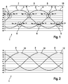
- the FIG. 1 shows a diagram 1, which represents three phase current waveforms 2, which were determined from Meßstromverierin not shown.
- the phase current profiles 2 are associated with a power network, not shown, which has three phases U, V and W, which each lead one of the currents I'_U, I'_V and I'_W.
- a first phase current curve 3 corresponds to the profile of the current I'-U
- a second phase current profile 4 to the profile of the current I'-V
- a third phase current curve 5 to the profile of the current I'_W.
- two measuring current curves were measured in the power network, which describe the characteristics of the currents I1_gem and I2_gem.
- the phase current profiles 2 have discontinuities 6, wherein configurations of the discontinuities 6 are equal between the phase current curves 2.
- four different jumps Spr_11, Spr_12, Spr_21 and Spr_22 are arranged.
- the jump Spr_11 leads on the example of the phase current waveform 3 to an increase for a period of time 7.
- the jump Spr_12 leads to a drop of the phase current curve 3 for a period 8, wherein the jump Spr_12 has the same jump height as the jump Spr_11.
- the jump Spr_21 leads to a renewed increase in the phase current profile 3, wherein the renewed increase is smaller than the rise of the jump Spr_21, the resulting rise for a period of time 9 applies.
- the jump heights are not limited to the heights and ratios shown.
- the jump Spr_22 which lowers the phase current curve 3 for the period 10, with the jumps Spr_21 and Spr_22 having the same jump height.
- the sequence of these jumps Spr_11, Spr_12, Spr_21 and Spr_22 occurs periodically and is the same for all phase current curves 2, whereby a corresponding time shift between the phase current curves 2 has to be considered.
- the FIG. 2 shows the diagram 1 with corrected phase current waveforms 2, which are sinusoidal waveforms 12.
- corrected phase current waveforms 2 To obtain the individual sections of the affected with discontinuities 6 phase current waveforms 2 from the FIG. 1 , as shown by the example of the phase current curve 3 in the time sections 7, 8, 9 and 10 along the jumps Spr_11, Spr_12, Spr_21 and Spr_22 shifted by a part of their associated jump heights.
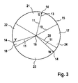
- the FIG. 3 shows a rotating phase vector 13, which represents the three phases U, V and W of the power grid.
- a phase vector 13 for example, serve a voltage vector, which is known about a further, additional measurement in the power grid or from a controller for the power network out.
- the phase vector 13 rotates counterclockwise.
- the rotating phase vector 13 has three phase vector branches 11, each phase vector branch 11 being associated with a phase U, V or W, furthermore the phase vector branches 11 are arranged at an angle of 120 ° to each other and all run with a peak 14 on a circular orbit 15 In addition, a horizontal straight line 17 passes through the center 16.
- the vertical distance of the peaks 14 from the straight line 17 corresponds to the instantaneous current value of the current I'_U, I'_V or I'_W associated with the phase U, V or W.
- the circle 18 enclosed by the circular orbit 15 is subdivided into four circle segments 21, 22, 23 and 24 by two straight lines 19 and 20, which run through the center point 16.
- the individual circle segments 21, 22, 23 and 24 determine how the phase current profile 2 is determined. If one of the phase vector branches 11 lies in the circular segment 21, then the phase current profile 2 assigned to the phase vector branch 11 is taken directly from the measuring current profile of the current I1_gem.
- phase current profile 2 from the measuring current profiles of the currents I1_gem and I2_gem is calculated for the corresponding phase U, V or W. If one of the phase vector branches 11 is in segment 23, the phase current profile 2 for the corresponding phase U, V or W is taken directly from the measurement current profile of the current I 2_gem. If one of the phase vector branches 11 lies in the circle segment 24, the phase current profile 2 is calculated for the corresponding phase U, V or W on the basis of the measuring current profiles I1_gem and I2_gem.
- FIG. 3 illustrated orbit 15 shows an error-free circular shape, resulting in the phase current waveforms 2 sinusoidal waveforms 12, as shown in FIG. 2 is shown. The location of the rotating phase vector 13 and thus the position of the phase vector branches 11 is determined by the rotation angle of the phase vector.
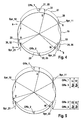
- FIG. 4 shows the representation of FIG. 3 , wherein additionally an orbit 26 is shown, which contains four discontinuities 6, which divides the orbit into four orbit segments 27, 28, 29 and 30.
- the orbit 26 represents the phase current waveforms 2 of FIG. 1
- the jump points 6 find their correspondences in the jumps Spr_11, Spr_12, Spr_21 and Spr_22.
- the orbit segments 27, 28, 29 and 30 each time a period 7, 8, 9 or 10 of the FIG. 1 assigned.
- the orbit segment 27 is assigned to the time segment 7, the orbit segment 28 to the time segment 8, the orbit segment 29 to the time segment 9 and the orbit segment 30 to the period 10.
- the orbit 26 shows different displacements 31, 32, 33 and 34 at various points in relation to the orbit 15, wherein the amounts of the displacements 31, 32 and 33 are different and the amounts of the displacements 32 and 34 are equal.
- the displacements 32 and 34 also represent an additional error 36.
- the displacements 31, 32, 33 and 34 each represent an inaccuracy 35, which prevails in their respective orbit segment 27, 28, 29 and 30. It thus results in an individual parallel displacement for each orbit segment 27, 28, 29 and 30 with respect to the orbit 15.
- real error values of the currents I1_gem and I2_gem were used.
- the current value of the displacement 31 is designated Offs_1
- the current value of the displacement 33 is designated Offs_2
- the current value of the displacements 32 and 34 is designated Offs_3.
- discontinuities 6 occur where a phase vector branch 11 changes from one segment 21, 22, 23 or 24 into another circle segment 21, 22, 23 or 24. Due to the arrangement of the circle segments 21, 22, 23 and 24 always arise simultaneously in two different phases U, V and / or W each have a discontinuity 6, wherein the types of discontinuities 6 between the phases U, V or W differ from each other. In particular, there is a relationship between simultaneously occurring discontinuities of different phases U, V or W, such that their jump heights are equal in terms of amount, but differ in sign.
- Offs_ 2 2 3 ⁇ Spr_ 21 - 1 3 ⁇ Spr_ 11
- Offs_ 1 2 3 ⁇ Spr_ 11 - 1 3 ⁇ Spr_ 21
- FIG. 6 shows the inventive method 37, wherein the method 37, the measured currents I1'_gem and I2'_gem via arrows 38 and 39 are supplied.
- Arrows 38 and 39 terminate in a correction unit 40 which calculates corrected currents I1 and I2 according to equations (8) and (9).
- the correction unit 40 is supplied with the current values Offs_1 and Offs_2 via arrows 41 and 42.
- the corrected currents I1 and I2 are forwarded via arrows 43 and 44 to a conversion unit 45, which converts the corrected currents I1 and I2 into the phase currents I'_U, I'_V and I'_W.
- the conversion is done by the in the FIGS. 3 to 5 explained method by means of a rotating phase vector 13.
- the three currents I'_U, I'_V and I'_W are provided via arrows 46, 47 and 48 for further analysis and processing.
- an arrow 49, 50 and 51 each goes off, which forward the currents I'_U, I'_V and I'_W to a jump determination 52.
- the jump determination 52 analyzes the phase current profiles 2, which are formed by the currents I'_U, I'_V and I'_W, and at the point in time of a jump 6 gives the current jumps Spr_11_a and Spr_21_a and their jump height via arrows 53 and 54 to a fault determination 55 - Also referred to as offset determination - continue.
- the error determination 55 calculates the current values Offs_1 and Offs_2, which are again transferred to the correction unit 40 via the arrows 41 and 42. Since the times of potential jump points 6 are known by the rotating phase vector 13, the corresponding current values of the jump heights of the jumps Spr_11_a or Spr_21_a can also be measured and evaluated at exactly this point in time. In all of this, it should be noted that always one of the three currents I'_U, I'_V or I'_W must be calculated using the node rule. Finally, this method leads to a continuous sinusoidal current waveform 12 for the currents I'_U, I'_V and I'_W of the phases U, V and W.
- the FIG. 7 shows a detailed view of the error detection 55 from FIG. 6 ,
- the error determination 55 has an error calculation 56, which forwards current values Offs_1_a and Offs_2_a to an error controller 59 by means of arrows 57 and 58.
- the current values Offs_1_a and Offs_2_a are supplied to a subtracter 60, to which a setpoint value 61 is fed via an arrow 62.
- the setpoint 61 is zero.
- the result of the subtractor 60 is forwarded by means of an arrow 63 to a gain element 64, which transmits the amplified signal via an arrow 65 to an adder 66.
- the result of the adder 66 is transmitted via an arrow 67 to a delay element 68, which is sent via an arrow 69 at the time of a jump 6, a trigger signal, whereby the delay element is switched further.
- the result of the delay element 68 corresponds in each case to the current values Offs_1 and Offs_2. Via an arrow 70, these values are fed back to summer 66.
- the error calculation 56 calculates the current values Offs_1_a and Offs_2_a using equations (6) and (7), in which case Offs_1 is replaced by Offs_1_a and Offs_2 by Offs_2_a in the equations. These values are first applied to a desired value 61 in the subtractor 60 and then amplified in the amplifier 64.
- the amplifier 64 thus serves as a P element 71 of the error controller 59.
- the delay element 68 together with the summer 66, an I element 72 of the error controller 59, which integrates at each discontinuity 6, if the I element via the arrow 69, the trigger signal is transmitted.
- the jumps Spr_11, Spur_12, Spr_21 and Spr_22 occur for the currents I'_U, I'_V and I'_W of the phase-current profiles 2, respectively. As in FIG. 1 set out, they each form pairs of equal jump heights. Therefore, only the jumps Spr_11 and Spr_21 were selected for the considerations presented here.
Landscapes
- Engineering & Computer Science (AREA)
- Power Engineering (AREA)
- Physics & Mathematics (AREA)
- General Physics & Mathematics (AREA)
- Control Of Ac Motors In General (AREA)
- Testing Electric Properties And Detecting Electric Faults (AREA)
Applications Claiming Priority (1)
| Application Number | Priority Date | Filing Date | Title |
|---|---|---|---|
| DE102008001586A DE102008001586A1 (de) | 2008-05-06 | 2008-05-06 | Verfahren zur Fehlerkorrektur bei einer Strommessung in einem mehrphasigen Stromnetz |
Publications (3)
| Publication Number | Publication Date |
|---|---|
| EP2116856A2 true EP2116856A2 (fr) | 2009-11-11 |
| EP2116856A3 EP2116856A3 (fr) | 2014-05-07 |
| EP2116856B1 EP2116856B1 (fr) | 2018-08-15 |
Family
ID=41087365
Family Applications (1)
| Application Number | Title | Priority Date | Filing Date |
|---|---|---|---|
| EP09100170.1A Not-in-force EP2116856B1 (fr) | 2008-05-06 | 2009-03-10 | Procédé de correction des erreurs lors de la mesure de courant dans un secteur multiphasé |
Country Status (2)
| Country | Link |
|---|---|
| EP (1) | EP2116856B1 (fr) |
| DE (1) | DE102008001586A1 (fr) |
Cited By (1)
| Publication number | Priority date | Publication date | Assignee | Title |
|---|---|---|---|---|
| CN113272666A (zh) * | 2018-12-27 | 2021-08-17 | 罗伯特·博世有限公司 | 用于获取电流测量装置的增强误差的方法 |
Families Citing this family (2)
| Publication number | Priority date | Publication date | Assignee | Title |
|---|---|---|---|---|
| WO2018188731A1 (fr) | 2017-04-11 | 2018-10-18 | Muehlbauer GmbH & Co. KG | Dispositif de réception pour composant pourvu d'un capteur optique |
| DE102024201839A1 (de) * | 2024-02-28 | 2025-08-28 | Schaeffler Technologies AG & Co. KG | Störungsbereinigte Stromerfassung in einem Inverter |
Family Cites Families (5)
| Publication number | Priority date | Publication date | Assignee | Title |
|---|---|---|---|---|
| DE4013089A1 (de) * | 1990-04-25 | 1991-10-31 | Bosch Gmbh Robert | Verfahren zur fehlerkorrigierten messung einer elektrischen groesse |
| US5436819A (en) * | 1991-07-25 | 1995-07-25 | Mitsubishi Denki Kabushiki Kaisha | Apparatus for and method of compensating for an output voltage error in an inverter output |
| JP4367130B2 (ja) * | 2001-09-29 | 2009-11-18 | ダイキン工業株式会社 | 相電流検出方法、インバータ制御方法、モータ制御方法およびこれらの装置 |
| JP4474827B2 (ja) * | 2002-10-11 | 2010-06-09 | ダイキン工業株式会社 | モータ駆動方法およびその装置 |
| US7348758B2 (en) * | 2005-10-26 | 2008-03-25 | International Rectifier Corporation | Audible noise reduction for single current shunt platform |
-
2008
- 2008-05-06 DE DE102008001586A patent/DE102008001586A1/de not_active Withdrawn
-
2009
- 2009-03-10 EP EP09100170.1A patent/EP2116856B1/fr not_active Not-in-force
Cited By (2)
| Publication number | Priority date | Publication date | Assignee | Title |
|---|---|---|---|---|
| CN113272666A (zh) * | 2018-12-27 | 2021-08-17 | 罗伯特·博世有限公司 | 用于获取电流测量装置的增强误差的方法 |
| CN113272666B (zh) * | 2018-12-27 | 2024-05-14 | 罗伯特·博世有限公司 | 用于获取电流测量装置的增强误差的方法 |
Also Published As
| Publication number | Publication date |
|---|---|
| EP2116856A3 (fr) | 2014-05-07 |
| DE102008001586A1 (de) | 2009-11-12 |
| EP2116856B1 (fr) | 2018-08-15 |
Similar Documents
| Publication | Publication Date | Title |
|---|---|---|
| EP3531141A1 (fr) | Procédé et dispositif d'observation de l'état du réseau | |
| EP2357410B1 (fr) | Procédé et brûleur avec détection de flammes basée sur une mesure du courant d'ionisation | |
| EP2696175A1 (fr) | Procédé de détection du débit d'une pompe à centrifuge | |
| DE102015202693A1 (de) | Verfahren zur Strangstrombestimmung in einem elektrischen Mehrphasensystem | |
| EP2265964B1 (fr) | Procédé et dispositif de mesure du courant dans des lignes de phase | |
| EP2116856B1 (fr) | Procédé de correction des erreurs lors de la mesure de courant dans un secteur multiphasé | |
| DE3514155C2 (fr) | ||
| EP3164724B1 (fr) | Procédé et dispositif de contrôle d'un commutateur à gradins d'un transformateur | |
| EP3164726B1 (fr) | Procédé et dispositif de contrôle d'un commutateur à gradins d'un transformateur | |
| EP1340988B1 (fr) | Méthode et appareil pour mesurer l'impedance dans un réseau d'alimentation électrique | |
| EP2593800B1 (fr) | Procédé ou système de détection de tension pour déterminer un paramètre de correction pour un canal de mesure et pour détecter une tension aux bornes d'un moteur électrique | |
| EP3058381B1 (fr) | Procédé de mesure de tensions d'alimentation d'un consommateur et consommateur | |
| EP2777144B1 (fr) | Procédé d'étalonnage d'un onduleur multiphasé, dispositif pour faire fonctionner un programme d'ordinateur et produit de programme d'ordinateur | |
| DE102015205772B3 (de) | Verfahren zur Erzeugung eines Geschwindigkeitssignals eines Elektromotors | |
| EP1853927B1 (fr) | Detecteur de mouvement equipé d'un circuit de surveillance d'un encodeur et procede correspondent de surveillance d'un encodeur | |
| EP3014756B1 (fr) | Procédé permettant de détecter une mauvaise position angulaire d'un moteur électrique | |
| DE102010006581B4 (de) | Schaltungsanordnung und Verfahren zur Ermittlung der aktuellen Position eines Rotors eines Elektromotors | |
| EP3164725B1 (fr) | Procédé et dispositif de contrôle d'un commutateur à gradins d'un transformateur | |
| EP3938755B1 (fr) | Procédé et dispositif de régulation pour réguler une vitesse de rotation | |
| EP2057726B1 (fr) | Procédé et système de protection différentielle | |
| EP3374696A1 (fr) | Procédé et dispositif de détection de signal de flamme | |
| DE102007021079A1 (de) | Verfahren zur Bestimmung von Arbeit/Leistung | |
| DE102020102647B4 (de) | Anordnung und Verfahren zur Erzeugung eines Verstärkungssignals für Messverstärker | |
| EP4431878B1 (fr) | Agencement de capteurs | |
| DE102019210569A1 (de) | Sensorlose Detektion von Wälzlagerschäden |
Legal Events
| Date | Code | Title | Description |
|---|---|---|---|
| PUAI | Public reference made under article 153(3) epc to a published international application that has entered the european phase |
Free format text: ORIGINAL CODE: 0009012 |
|
| AK | Designated contracting states |
Kind code of ref document: A2 Designated state(s): AT BE BG CH CY CZ DE DK EE ES FI FR GB GR HR HU IE IS IT LI LT LU LV MC MK MT NL NO PL PT RO SE SI SK TR |
|
| AX | Request for extension of the european patent |
Extension state: AL BA RS |
|
| PUAL | Search report despatched |
Free format text: ORIGINAL CODE: 0009013 |
|
| AK | Designated contracting states |
Kind code of ref document: A3 Designated state(s): AT BE BG CH CY CZ DE DK EE ES FI FR GB GR HR HU IE IS IT LI LT LU LV MC MK MT NL NO PL PT RO SE SI SK TR |
|
| AX | Request for extension of the european patent |
Extension state: AL BA RS |
|
| RIC1 | Information provided on ipc code assigned before grant |
Ipc: G01R 19/00 20060101AFI20140331BHEP Ipc: G01R 25/00 20060101ALN20140331BHEP |
|
| 17P | Request for examination filed |
Effective date: 20141107 |
|
| RBV | Designated contracting states (corrected) |
Designated state(s): AT BE BG CH CY CZ DE DK EE ES FI FR GB GR HR HU IE IS IT LI LT LU LV MC MK MT NL NO PL PT RO SE SI SK TR |
|
| AKX | Designation fees paid |
Designated state(s): AT BE BG CH CY CZ DE DK EE ES FI FR GB GR HR HU IE IS IT LI LT LU LV MC MK MT NL NO PL PT RO SE SI SK TR |
|
| AXX | Extension fees paid |
Extension state: RS Extension state: BA Extension state: AL |
|
| GRAP | Despatch of communication of intention to grant a patent |
Free format text: ORIGINAL CODE: EPIDOSNIGR1 |
|
| STAA | Information on the status of an ep patent application or granted ep patent |
Free format text: STATUS: GRANT OF PATENT IS INTENDED |
|
| RIC1 | Information provided on ipc code assigned before grant |
Ipc: H02M 1/00 20060101ALI20180503BHEP Ipc: G01R 25/00 20060101ALN20180503BHEP Ipc: G01R 19/00 20060101AFI20180503BHEP Ipc: H02M 7/5387 20070101ALI20180503BHEP |
|
| INTG | Intention to grant announced |
Effective date: 20180518 |
|
| RIC1 | Information provided on ipc code assigned before grant |
Ipc: H02M 1/00 20060101ALI20180507BHEP Ipc: G01R 19/00 20060101AFI20180507BHEP Ipc: G01R 25/00 20060101ALN20180507BHEP Ipc: H02M 7/5387 20070101ALI20180507BHEP |
|
| RIN1 | Information on inventor provided before grant (corrected) |
Inventor name: FINKE, SVEN Inventor name: KUEHN, TIMO |
|
| GRAS | Grant fee paid |
Free format text: ORIGINAL CODE: EPIDOSNIGR3 |
|
| GRAA | (expected) grant |
Free format text: ORIGINAL CODE: 0009210 |
|
| STAA | Information on the status of an ep patent application or granted ep patent |
Free format text: STATUS: THE PATENT HAS BEEN GRANTED |
|
| AK | Designated contracting states |
Kind code of ref document: B1 Designated state(s): AT BE BG CH CY CZ DE DK EE ES FI FR GB GR HR HU IE IS IT LI LT LU LV MC MK MT NL NO PL PT RO SE SI SK TR |
|
| REG | Reference to a national code |
Ref country code: CH Ref legal event code: EP Ref country code: GB Ref legal event code: FG4D Free format text: NOT ENGLISH Ref country code: AT Ref legal event code: REF Ref document number: 1030390 Country of ref document: AT Kind code of ref document: T Effective date: 20180815 |
|
| REG | Reference to a national code |
Ref country code: IE Ref legal event code: FG4D Free format text: LANGUAGE OF EP DOCUMENT: GERMAN |
|
| REG | Reference to a national code |
Ref country code: DE Ref legal event code: R096 Ref document number: 502009015188 Country of ref document: DE |
|
| REG | Reference to a national code |
Ref country code: NL Ref legal event code: MP Effective date: 20180815 |
|
| REG | Reference to a national code |
Ref country code: LT Ref legal event code: MG4D |
|
| PG25 | Lapsed in a contracting state [announced via postgrant information from national office to epo] |
Ref country code: GR Free format text: LAPSE BECAUSE OF FAILURE TO SUBMIT A TRANSLATION OF THE DESCRIPTION OR TO PAY THE FEE WITHIN THE PRESCRIBED TIME-LIMIT Effective date: 20181116 Ref country code: IS Free format text: LAPSE BECAUSE OF FAILURE TO SUBMIT A TRANSLATION OF THE DESCRIPTION OR TO PAY THE FEE WITHIN THE PRESCRIBED TIME-LIMIT Effective date: 20181215 Ref country code: NO Free format text: LAPSE BECAUSE OF FAILURE TO SUBMIT A TRANSLATION OF THE DESCRIPTION OR TO PAY THE FEE WITHIN THE PRESCRIBED TIME-LIMIT Effective date: 20181115 Ref country code: LT Free format text: LAPSE BECAUSE OF FAILURE TO SUBMIT A TRANSLATION OF THE DESCRIPTION OR TO PAY THE FEE WITHIN THE PRESCRIBED TIME-LIMIT Effective date: 20180815 Ref country code: FI Free format text: LAPSE BECAUSE OF FAILURE TO SUBMIT A TRANSLATION OF THE DESCRIPTION OR TO PAY THE FEE WITHIN THE PRESCRIBED TIME-LIMIT Effective date: 20180815 Ref country code: NL Free format text: LAPSE BECAUSE OF FAILURE TO SUBMIT A TRANSLATION OF THE DESCRIPTION OR TO PAY THE FEE WITHIN THE PRESCRIBED TIME-LIMIT Effective date: 20180815 Ref country code: BG Free format text: LAPSE BECAUSE OF FAILURE TO SUBMIT A TRANSLATION OF THE DESCRIPTION OR TO PAY THE FEE WITHIN THE PRESCRIBED TIME-LIMIT Effective date: 20181115 Ref country code: SE Free format text: LAPSE BECAUSE OF FAILURE TO SUBMIT A TRANSLATION OF THE DESCRIPTION OR TO PAY THE FEE WITHIN THE PRESCRIBED TIME-LIMIT Effective date: 20180815 |
|
| PG25 | Lapsed in a contracting state [announced via postgrant information from national office to epo] |
Ref country code: LV Free format text: LAPSE BECAUSE OF FAILURE TO SUBMIT A TRANSLATION OF THE DESCRIPTION OR TO PAY THE FEE WITHIN THE PRESCRIBED TIME-LIMIT Effective date: 20180815 Ref country code: HR Free format text: LAPSE BECAUSE OF FAILURE TO SUBMIT A TRANSLATION OF THE DESCRIPTION OR TO PAY THE FEE WITHIN THE PRESCRIBED TIME-LIMIT Effective date: 20180815 Ref country code: ES Free format text: LAPSE BECAUSE OF FAILURE TO SUBMIT A TRANSLATION OF THE DESCRIPTION OR TO PAY THE FEE WITHIN THE PRESCRIBED TIME-LIMIT Effective date: 20180815 |
|
| PG25 | Lapsed in a contracting state [announced via postgrant information from national office to epo] |
Ref country code: PL Free format text: LAPSE BECAUSE OF FAILURE TO SUBMIT A TRANSLATION OF THE DESCRIPTION OR TO PAY THE FEE WITHIN THE PRESCRIBED TIME-LIMIT Effective date: 20180815 Ref country code: RO Free format text: LAPSE BECAUSE OF FAILURE TO SUBMIT A TRANSLATION OF THE DESCRIPTION OR TO PAY THE FEE WITHIN THE PRESCRIBED TIME-LIMIT Effective date: 20180815 Ref country code: CZ Free format text: LAPSE BECAUSE OF FAILURE TO SUBMIT A TRANSLATION OF THE DESCRIPTION OR TO PAY THE FEE WITHIN THE PRESCRIBED TIME-LIMIT Effective date: 20180815 Ref country code: EE Free format text: LAPSE BECAUSE OF FAILURE TO SUBMIT A TRANSLATION OF THE DESCRIPTION OR TO PAY THE FEE WITHIN THE PRESCRIBED TIME-LIMIT Effective date: 20180815 |
|
| REG | Reference to a national code |
Ref country code: DE Ref legal event code: R097 Ref document number: 502009015188 Country of ref document: DE |
|
| PG25 | Lapsed in a contracting state [announced via postgrant information from national office to epo] |
Ref country code: SK Free format text: LAPSE BECAUSE OF FAILURE TO SUBMIT A TRANSLATION OF THE DESCRIPTION OR TO PAY THE FEE WITHIN THE PRESCRIBED TIME-LIMIT Effective date: 20180815 Ref country code: DK Free format text: LAPSE BECAUSE OF FAILURE TO SUBMIT A TRANSLATION OF THE DESCRIPTION OR TO PAY THE FEE WITHIN THE PRESCRIBED TIME-LIMIT Effective date: 20180815 |
|
| PLBE | No opposition filed within time limit |
Free format text: ORIGINAL CODE: 0009261 |
|
| STAA | Information on the status of an ep patent application or granted ep patent |
Free format text: STATUS: NO OPPOSITION FILED WITHIN TIME LIMIT |
|
| 26N | No opposition filed |
Effective date: 20190516 |
|
| PG25 | Lapsed in a contracting state [announced via postgrant information from national office to epo] |
Ref country code: SI Free format text: LAPSE BECAUSE OF FAILURE TO SUBMIT A TRANSLATION OF THE DESCRIPTION OR TO PAY THE FEE WITHIN THE PRESCRIBED TIME-LIMIT Effective date: 20180815 |
|
| PG25 | Lapsed in a contracting state [announced via postgrant information from national office to epo] |
Ref country code: MC Free format text: LAPSE BECAUSE OF FAILURE TO SUBMIT A TRANSLATION OF THE DESCRIPTION OR TO PAY THE FEE WITHIN THE PRESCRIBED TIME-LIMIT Effective date: 20180815 |
|
| REG | Reference to a national code |
Ref country code: CH Ref legal event code: PL |
|
| GBPC | Gb: european patent ceased through non-payment of renewal fee |
Effective date: 20190310 |
|
| PG25 | Lapsed in a contracting state [announced via postgrant information from national office to epo] |
Ref country code: LU Free format text: LAPSE BECAUSE OF NON-PAYMENT OF DUE FEES Effective date: 20190310 |
|
| REG | Reference to a national code |
Ref country code: BE Ref legal event code: MM Effective date: 20190331 |
|
| PG25 | Lapsed in a contracting state [announced via postgrant information from national office to epo] |
Ref country code: IE Free format text: LAPSE BECAUSE OF NON-PAYMENT OF DUE FEES Effective date: 20190310 Ref country code: GB Free format text: LAPSE BECAUSE OF NON-PAYMENT OF DUE FEES Effective date: 20190310 Ref country code: LI Free format text: LAPSE BECAUSE OF NON-PAYMENT OF DUE FEES Effective date: 20190331 Ref country code: CH Free format text: LAPSE BECAUSE OF NON-PAYMENT OF DUE FEES Effective date: 20190331 |
|
| PG25 | Lapsed in a contracting state [announced via postgrant information from national office to epo] |
Ref country code: BE Free format text: LAPSE BECAUSE OF NON-PAYMENT OF DUE FEES Effective date: 20190331 |
|
| PG25 | Lapsed in a contracting state [announced via postgrant information from national office to epo] |
Ref country code: TR Free format text: LAPSE BECAUSE OF FAILURE TO SUBMIT A TRANSLATION OF THE DESCRIPTION OR TO PAY THE FEE WITHIN THE PRESCRIBED TIME-LIMIT Effective date: 20180815 |
|
| PGFP | Annual fee paid to national office [announced via postgrant information from national office to epo] |
Ref country code: IT Payment date: 20200325 Year of fee payment: 12 |
|
| PG25 | Lapsed in a contracting state [announced via postgrant information from national office to epo] |
Ref country code: PT Free format text: LAPSE BECAUSE OF FAILURE TO SUBMIT A TRANSLATION OF THE DESCRIPTION OR TO PAY THE FEE WITHIN THE PRESCRIBED TIME-LIMIT Effective date: 20181215 Ref country code: MT Free format text: LAPSE BECAUSE OF FAILURE TO SUBMIT A TRANSLATION OF THE DESCRIPTION OR TO PAY THE FEE WITHIN THE PRESCRIBED TIME-LIMIT Effective date: 20180815 |
|
| PGFP | Annual fee paid to national office [announced via postgrant information from national office to epo] |
Ref country code: FR Payment date: 20200325 Year of fee payment: 12 |
|
| REG | Reference to a national code |
Ref country code: AT Ref legal event code: MM01 Ref document number: 1030390 Country of ref document: AT Kind code of ref document: T Effective date: 20190310 |
|
| PG25 | Lapsed in a contracting state [announced via postgrant information from national office to epo] |
Ref country code: AT Free format text: LAPSE BECAUSE OF NON-PAYMENT OF DUE FEES Effective date: 20190310 |
|
| PG25 | Lapsed in a contracting state [announced via postgrant information from national office to epo] |
Ref country code: CY Free format text: LAPSE BECAUSE OF FAILURE TO SUBMIT A TRANSLATION OF THE DESCRIPTION OR TO PAY THE FEE WITHIN THE PRESCRIBED TIME-LIMIT Effective date: 20180815 |
|
| PG25 | Lapsed in a contracting state [announced via postgrant information from national office to epo] |
Ref country code: HU Free format text: LAPSE BECAUSE OF FAILURE TO SUBMIT A TRANSLATION OF THE DESCRIPTION OR TO PAY THE FEE WITHIN THE PRESCRIBED TIME-LIMIT; INVALID AB INITIO Effective date: 20090310 |
|
| PG25 | Lapsed in a contracting state [announced via postgrant information from national office to epo] |
Ref country code: FR Free format text: LAPSE BECAUSE OF NON-PAYMENT OF DUE FEES Effective date: 20210331 |
|
| PG25 | Lapsed in a contracting state [announced via postgrant information from national office to epo] |
Ref country code: IT Free format text: LAPSE BECAUSE OF NON-PAYMENT OF DUE FEES Effective date: 20210310 |
|
| PG25 | Lapsed in a contracting state [announced via postgrant information from national office to epo] |
Ref country code: MK Free format text: LAPSE BECAUSE OF FAILURE TO SUBMIT A TRANSLATION OF THE DESCRIPTION OR TO PAY THE FEE WITHIN THE PRESCRIBED TIME-LIMIT Effective date: 20180815 |
|
| PGFP | Annual fee paid to national office [announced via postgrant information from national office to epo] |
Ref country code: DE Payment date: 20220525 Year of fee payment: 14 |
|
| REG | Reference to a national code |
Ref country code: DE Ref legal event code: R119 Ref document number: 502009015188 Country of ref document: DE |
|
| PG25 | Lapsed in a contracting state [announced via postgrant information from national office to epo] |
Ref country code: DE Free format text: LAPSE BECAUSE OF NON-PAYMENT OF DUE FEES Effective date: 20231003 |