EP3531141A1 - Procédé et dispositif d'observation de l'état du réseau - Google Patents
Procédé et dispositif d'observation de l'état du réseau Download PDFInfo
- Publication number
- EP3531141A1 EP3531141A1 EP19163252.0A EP19163252A EP3531141A1 EP 3531141 A1 EP3531141 A1 EP 3531141A1 EP 19163252 A EP19163252 A EP 19163252A EP 3531141 A1 EP3531141 A1 EP 3531141A1
- Authority
- EP
- European Patent Office
- Prior art keywords
- frequency
- network
- auxiliary
- voltage
- phase
- Prior art date
- Legal status (The legal status is an assumption and is not a legal conclusion. Google has not performed a legal analysis and makes no representation as to the accuracy of the status listed.)
- Granted
Links
Images


Classifications
-
- F—MECHANICAL ENGINEERING; LIGHTING; HEATING; WEAPONS; BLASTING
- F03—MACHINES OR ENGINES FOR LIQUIDS; WIND, SPRING, OR WEIGHT MOTORS; PRODUCING MECHANICAL POWER OR A REACTIVE PROPULSIVE THRUST, NOT OTHERWISE PROVIDED FOR
- F03D—WIND MOTORS
- F03D9/00—Adaptations of wind motors for special use; Combinations of wind motors with apparatus driven thereby; Wind motors specially adapted for installation in particular locations
- F03D9/20—Wind motors characterised by the driven apparatus
- F03D9/25—Wind motors characterised by the driven apparatus the apparatus being an electrical generator
- F03D9/255—Wind motors characterised by the driven apparatus the apparatus being an electrical generator connected to electrical distribution networks; Arrangements therefor
-
- G—PHYSICS
- G01—MEASURING; TESTING
- G01R—MEASURING ELECTRIC VARIABLES; MEASURING MAGNETIC VARIABLES
- G01R19/00—Arrangements for measuring currents or voltages or for indicating presence or sign thereof
- G01R19/25—Arrangements for measuring currents or voltages or for indicating presence or sign thereof using digital measurement techniques
- G01R19/2513—Arrangements for monitoring electric power systems, e.g. power lines or loads; Logging
-
- G—PHYSICS
- G01—MEASURING; TESTING
- G01R—MEASURING ELECTRIC VARIABLES; MEASURING MAGNETIC VARIABLES
- G01R23/00—Arrangements for measuring frequencies; Arrangements for analysing frequency spectra
- G01R23/02—Arrangements for measuring frequency, e.g. pulse repetition rate; Arrangements for measuring period of current or voltage
-
- G—PHYSICS
- G01—MEASURING; TESTING
- G01R—MEASURING ELECTRIC VARIABLES; MEASURING MAGNETIC VARIABLES
- G01R25/00—Arrangements for measuring phase angle between a voltage and a current or between voltages or currents
-
- H—ELECTRICITY
- H02—GENERATION; CONVERSION OR DISTRIBUTION OF ELECTRIC POWER
- H02J—ELECTRIC POWER NETWORKS; CIRCUIT ARRANGEMENTS OR SYSTEMS FOR SUPPLYING OR DISTRIBUTING ELECTRIC POWER; SYSTEMS FOR STORING ELECTRIC ENERGY
- H02J3/00—Circuit arrangements for AC mains or AC distribution networks
- H02J3/38—Arrangements for feeding a single network from two or more generators or sources in parallel; Arrangements for feeding already energised networks from additional generators or sources in parallel
- H02J3/381—Dispersed generators
-
- H—ELECTRICITY
- H02—GENERATION; CONVERSION OR DISTRIBUTION OF ELECTRIC POWER
- H02J—ELECTRIC POWER NETWORKS; CIRCUIT ARRANGEMENTS OR SYSTEMS FOR SUPPLYING OR DISTRIBUTING ELECTRIC POWER; SYSTEMS FOR STORING ELECTRIC ENERGY
- H02J2101/00—Supply or distribution of decentralised, dispersed or local electric power generation
- H02J2101/20—Dispersed power generation using renewable energy sources
- H02J2101/28—Wind energy
-
- H—ELECTRICITY
- H02—GENERATION; CONVERSION OR DISTRIBUTION OF ELECTRIC POWER
- H02J—ELECTRIC POWER NETWORKS; CIRCUIT ARRANGEMENTS OR SYSTEMS FOR SUPPLYING OR DISTRIBUTING ELECTRIC POWER; SYSTEMS FOR STORING ELECTRIC ENERGY
- H02J3/00—Circuit arrangements for AC mains or AC distribution networks
- H02J3/38—Arrangements for feeding a single network from two or more generators or sources in parallel; Arrangements for feeding already energised networks from additional generators or sources in parallel
- H02J3/40—Synchronisation of generators for connection to a network or to another generator
- H02J3/44—Synchronisation of generators for connection to a network or to another generator with means for ensuring correct phase sequence
-
- Y—GENERAL TAGGING OF NEW TECHNOLOGICAL DEVELOPMENTS; GENERAL TAGGING OF CROSS-SECTIONAL TECHNOLOGIES SPANNING OVER SEVERAL SECTIONS OF THE IPC; TECHNICAL SUBJECTS COVERED BY FORMER USPC CROSS-REFERENCE ART COLLECTIONS [XRACs] AND DIGESTS
- Y02—TECHNOLOGIES OR APPLICATIONS FOR MITIGATION OR ADAPTATION AGAINST CLIMATE CHANGE
- Y02E—REDUCTION OF GREENHOUSE GAS [GHG] EMISSIONS, RELATED TO ENERGY GENERATION, TRANSMISSION OR DISTRIBUTION
- Y02E10/00—Energy generation through renewable energy sources
- Y02E10/70—Wind energy
- Y02E10/72—Wind turbines with rotation axis in wind direction
-
- Y—GENERAL TAGGING OF NEW TECHNOLOGICAL DEVELOPMENTS; GENERAL TAGGING OF CROSS-SECTIONAL TECHNOLOGIES SPANNING OVER SEVERAL SECTIONS OF THE IPC; TECHNICAL SUBJECTS COVERED BY FORMER USPC CROSS-REFERENCE ART COLLECTIONS [XRACs] AND DIGESTS
- Y02—TECHNOLOGIES OR APPLICATIONS FOR MITIGATION OR ADAPTATION AGAINST CLIMATE CHANGE
- Y02E—REDUCTION OF GREENHOUSE GAS [GHG] EMISSIONS, RELATED TO ENERGY GENERATION, TRANSMISSION OR DISTRIBUTION
- Y02E10/00—Energy generation through renewable energy sources
- Y02E10/70—Wind energy
- Y02E10/76—Power conversion electric or electronic aspects
Definitions
- the present invention relates to a method for detecting electrical variables of a 3-phase AC voltage network having a first, second and third phase. Furthermore, the present invention relates to a method for feeding electrical energy into an electrical alternating voltage network. Furthermore, the present invention relates to a device for detecting electrical variables of a 3-phase alternating voltage network and a device for feeding electrical energy into an electrical alternating voltage network. Moreover, the present invention also relates to a wind turbine, which is prepared for detecting electrical variables of an alternating voltage network and / or for feeding electrical energy into an electrical alternating voltage network.
- phase position of the zero crossing and the frequency or the two zero crossings can be determined.
- the disadvantage here is in particular that according to at least the duration of a half-period is necessary to detect the frequency and thus frequency changes. At the same time, the quality of such measuring methods may be insufficient. Especially for AC grids, which are increasingly fed and supported by decentralized power supply, the fastest possible measurement with the highest possible quality is important. The reliable and rapid detection of network disturbances, such as the occurrence of short circuits, is becoming increasingly important.
- the starting point is a 3-phase alternating voltage network with a first, second and third phase.
- the indication of a phase angle below basically refers to the first phase, unless stated otherwise.
- Indices of 1 to 3, in particular of voltages or phase angles, basically refer to the first, second and third phase, respectively.
- a voltage value namely a line voltage
- a first time of the first, second and third phase ie the voltage relative to the neutral conductor or another neutral potential.
- the next step is a transformation of the voltage values measured in polar coordinates into a complex-valued variable at the first time, whereby an amount and a phase angle are generated accordingly.
- the phase angle refers to the first voltage.
- the measuring and transforming is repeated for at least one more time.
- at least two points in time are transformed into polar coordinates Voltage measurement before.
- the frequency, the voltage amplitude and / or the phase angle of at least one of the phases are then determined from these values in polar coordinates.
- the process should be implemented digitally.
- the method steps described run at least partially in time from one another.
- the voltage of the three phases is measured, a transformation is carried out, and then the voltages of the three phases are measured again at a second point in time thereafter.
- an analogous reaction is also possible, whereby essentially a continuous measurement could be carried out.
- the current frequency, a voltage amplitude and the phases of the three voltages are calculated. Also preferably, the times of the measurement are less than a half-period - starting from the expected frequency - apart.
- a frequency control is used to determine the one effective frequency of the three alternating voltages, which expressly does not work according to the concept of the phase-locked loop (PLL) and corrects a first auxiliary frequency.
- a control loop is used for this purpose.
- the first auxiliary frequency is basically a state variable and a result of this control loop, which can be further utilized as an intermediate variable.
- the first auxiliary frequency itself can also be used as the received current frequency.
- an auxiliary angle can be determined. By comparing the phase angle, which was determined during the coordinate transformation, with the auxiliary phase angle, a variable for generating the first auxiliary frequency can be generated.
- a first differential angle is formed for frequency control.
- This first difference angle is obtained as the difference between the phase angle resulting from the coordinate transformation and a first auxiliary phase angle past a sampling time.
- This first differential angle could thus also be interpreted as frequency or differential frequency, because in any case the difference between a phase angle and a phase angle past a scanning step corresponds to a frequency.
- Said first difference angle is multiplied according to this embodiment with a first gain and / or added to an initial frequency value of a frequency to obtain the first auxiliary frequency.
- the first auxiliary phase angle becomes the first auxiliary frequency certainly.
- an expected frequency in particular the nominal frequency or corresponding to the nominal circuit frequency of the network can be used.
- a second auxiliary phase angle with a second auxiliary frequency.
- a second auxiliary frequency can - if necessary after filtering - be output as detected current frequency.
- such second auxiliary frequency and second auxiliary phase angle are based on the first auxiliary frequency and the first auxiliary phase angle, according to one of the previous embodiments.
- the second auxiliary frequency and the second auxiliary phase angle are preferably determined, in particular regulated, on the basis of a predetermined dynamic behavior as a function of the first auxiliary frequency and the first auxiliary phase angle.
- a second difference angle on the basis of the first auxiliary phase angle and the second auxiliary phase angle.
- This second difference angle is formed as the difference between the first auxiliary phase angle and the second auxiliary phase angle past a sampling time.
- the first and second auxiliary frequency is used as basis and determines an auxiliary difference frequency.
- the auxiliary difference frequency is formed as a difference between the second auxiliary frequency, one sampling time, and the first auxiliary frequency.
- an auxiliary angular acceleration is formed from the second difference angle and the auxiliary difference frequency.
- This auxiliary angular acceleration is representative of a second derivative of the second auxiliary phase angle with respect to time and the second auxiliary phase angle as well as the second auxiliary frequency are calculated from this auxiliary angular acceleration.
- the auxiliary angular acceleration is preferably formed as a difference between the second differential angle and the auxiliary differential frequency, wherein the second differential angle and / or the auxiliary differential frequency can each be taken into account multiplied by a gain factor.
- the difference formation with the auxiliary difference frequency which can also be referred to as connection of the auxiliary differential frequency with a gain factor - which in principle could also be 1 - depending on the choice of gain factors has a damping effect on the dynamics of the second auxiliary frequency, as far as the method steps or process characteristics can be interpreted in their effect.
- the voltage amplitude obtained during the transformation is output as the detected output voltage.
- the phase angle obtained in the transformation is differentiated by time - which may be discrete or continuous - and output as the detected frequency. Alternatively, this differentiated phase angle can also be output as the detected comparison frequency if, in particular, a further variable is output as the detected frequency.
- the second auxiliary frequency is output as the detected frequency and additionally or alternatively, the second auxiliary phase angle as the detected phase angle of a phase, in particular the first phase.
- the mentioned quantities can be filtered appropriately before being dispensed if necessary.
- the quantities to be output, in particular the second auxiliary frequency output as the detected frequency, and the second auxiliary phase angle output as the detected phase angle thus form a method product of the method.
- Such an output detected frequency and such an output detected phase angle is characterized in particular by a fast detection. That is, in particular, the output of a detected frequency, which has a change in frequency of the measured alternating voltage network in a period of less than half a period, already differs from a conventional frequency detection by measuring the voltage zero crossings.
- the method according to the invention could also be designed or implemented more slowly.
- the occurrence of a 3-phase short circuit can be detected in particular at the breaking in of the three phase voltages and thus at the breakdown of the transformed voltage amplitude.
- a 2-pin short circuit basically only one voltage breaks down, when measured on the d-side of a DY transformer (triangle-to-star transformer) and the 2-pin short circuit occurred on the D-piece. This can be detected, for example, at an oscillating voltage amplitude of the transformed voltage.
- the loss of angular stability which is also known as “loss of stability” (LOS) gives way to the differentiation of the phase angle d ⁇ dt from the mains frequency or the network frequency. To detect such a loss of angular stability, fast angle and frequency detection is desirable.
- LOS loss of stability
- a corresponding signal can be provided.
- a signal may be provided within a processor unit or output as an output signal.
- such a signal is to be considered as a product of the process.
- the fast and targeted detection of at least one of the mentioned network disturbances is a desired goal and records such a signal.
- the measurement of the electrical quantities is monitored for a network disturbance in order to detect any network disturbance. If a network failure occurs, the acquisition continues as an estimate based on recently used quantities.
- An actual detection can only be mentioned insofar as it is assumed that the electrical parameters of the alternating voltage network are essentially stationary.
- at least one estimate of the desired quantities takes place, with no or only partial adaptation of the estimated variables being carried out as a function of measured variables.
- the AC voltage network is monitored for the presence of at least the network disturbance of the loss of the angular stability and / or the network disturbance of the occurrence of an island network formation.
- measures for supporting the alternating voltage network are initiated.
- the occurrence of a 3-phase short circuit and / or the occurrence of a 2-pole short circuit is monitored and measures to support the AC network are initiated if at least one of said network disturbances occurs.
- Another embodiment proposes that the method for feeding electrical energy, a method according to the invention is used, in particular to determine the frequency and phase of the network as the basis for the feed, as well as to detect any network disturbances to quickly and purposefully initiate appropriate measures can.
- the feeding into the electrical alternating voltage network can then take place in a known manner, for example using a 3-phase inverter which, starting from a DC voltage intermediate circuit, generates the three phases by means of a corresponding pulse pattern with the aid of semiconductor switches.
- the respectively required information on frequency and phase can be provided by the method according to the invention.
- a measuring device for detecting electrical variables of a 3-phase AC electrical network which essentially implements a measuring method according to the invention.
- at least one measuring means is used for measuring the instantaneous electrical voltage of each of the three phases in relation to a neutral conductor, that is to say for measuring the phase voltages.
- a computing unit for determining the frequency and phase of the electrical network is provided.
- the measuring means deliver, in particular digitally, the measured voltages to the arithmetic unit at each sampling instant.
- the computing steps of the respective embodiment of the measuring method according to the invention are implemented on the arithmetic unit.
- the computational steps are to be implemented on a digital signal processor, although theoretically also the implementation by means of an analog computer or an analog circuit would be considered.
- a feed device for feeding electrical energy into an AC network.
- the feed device has at least one measuring device and a feed unit.
- the measuring device which is constructed and constructed in particular according to an embodiment described above, detects in particular frequency and phase of the AC electrical network. These quantities form the basis for feeding in and are to be provided in particular for synchronizing but also for detecting disturbances.
- a feeding unit is used, the feeding apparatus being controlled according to a feeding method described above.
- a feed unit may include a frequency inverter to convert electrical energy from a DC voltage intermediate circuit by means of corresponding semiconductor switches via a pulse method in a sinusoidal waveform per phase.
- a wind energy plant which takes in particular kinetic energy from the wind and converts it into electrical energy by means of a generator.
- the electrical energy is fed into a three-phase alternating voltage network.
- a feed device as described above is used.
- a measuring device as described above is proposed.
- the measuring device can be part of the feed device.
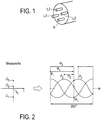
- the invention is based on a 3-phase connection point 2, which has three lines L1, L2 and L3 for guiding one phase each and a neutral conductor N, as in FIG Fig. 1 is shown. To illustrate, the connection point 2 is symbolized as a cable end. Likewise, the three phases L1, L2 and L3 and the neutral conductor N can be provided for example in a connection box.
- Fig. 2 illustrates the principle of the invention underlying the nature of the measurement. Accordingly, at a time t 1 of each of the conductors L1, L2 and L3 a voltage relative to the neutral conductor N is measured. These measured values u 1 , u 2 and u 3 can basically be assigned to a position in a 360 ° cut, namely a period duration. This is in Fig. 2 such a section of a period is shown for all three phases P1, P2 and P3. The corresponding position of the measurement at the time t 1 is assigned to the point M1 in the section of a period which is plotted over an angle ⁇ .
- phase angles ⁇ 1 , ⁇ 2 and ⁇ 3 thus relate to the angles from the voltage maximum - the peak value - of the respective phase to the measuring point M1.
- the respective phases are identified as P1, P2 and P3.
- the phase angle ⁇ 3 belongs to the phase P3.
- the peak value of the phase P3 lies beyond the point M1 and is thus illustrated by an arrow, which basically begins at the vertex of P3, to be measured by the end of the period shown, plus the value from the beginning the period to the measuring point M1.
- the phase angles ⁇ 1 , ⁇ 2 and ⁇ 3 would each be shifted by 120 ° or 240 ° from one another.
- the absolute amplitude of the phases P1, P2 and P3 is shown in the illustration Fig. 2 not on.
- the amplitude can be standardized for example for this representation.
- the period according to the illustration according to Fig. 2 is 360 ° or 2 ⁇ .
- Fig. 3 shows an overall structure of a three-phase network with neutral and connected measuring device 1 according to an embodiment of the invention.
- the measuring device 1 uses a measuring filter 4, which is connected for this purpose between the lines L1, L2 and L3 and the neutral conductor.
- Lines L1, L2 and L3 respectively carry the first, second and third phases.
- the voltage measured in each case between the resistor R and the capacitor C against the neutral conductor N is input to the measuring device 1 and further processed there and evaluated.
- Fig. 4 illustrates the internal structure of the measuring device 1, which can also be referred to as measuring and computing unit 1.
- the structure shown is basically designed as a discrete-time structure. Nevertheless, for the sake of clarity, the explanation is partly based on continuous-time Representations, in particular temporal derivatives, reference is made. Basically, both a discrete-time and a continuous-time implementation is possible.
- Fig. 4 illustrates the measuring filter 4 only by an RC element is executed only for one phase. In fact, the structure of the measuring filter 4 corresponds to that in FIG Fig. 3 shown.
- the respective voltage measurement values u 1 , u 2 and u 3 are input to the transformation block 6.
- the transformation block 6 the three voltage values u 1 , u 2 and u 3 are transformed into polar coordinates.
- the voltage U N and the angle ⁇ N are output from the transformation block 6.
- the voltage U N is applied to a first digital filter F1, which has a holding element T and a first amplification factor P 1 .
- the digital filter also has two summation points, each represented by a circle symbol. If a minus sign is displayed as a sign, the value of the relevant signal path is subtracted. Otherwise there is an addition, which incidentally also for the others in the Fig. 4 applies adders shown.
- the phase angle ⁇ N is derived time-discretely in a differentiator 8 and thus corresponds to an angular frequency, which in the Fig. 4 is entered as d ⁇ N / dt.
- This angular frequency or angular frequency is applied to a second digital filter F2, which corresponds in construction to the first digital filter F1 and has a second amplification factor P2.
- the result is an estimate of the frequency of the AC voltage ⁇ A , which is correspondingly output as an estimate of the frequency of the AC voltage ⁇ A.
- the phase angle ⁇ N is also input to a frequency locked loop 10.
- a first auxiliary frequency d ⁇ A / dt is determined and tracked in the sense of regulating the network frequency or network frequency, as far as the frequency control circuit 10 can be interpreted substantially.
- a first discrete-time integrator I1 is present, which determines a first auxiliary angle ⁇ A from the first auxiliary frequency d ⁇ 1A / dt.
- At the first summing point A1 is ⁇ of the current phase angle N of the past by one sampling first auxiliary angle ⁇ A deducted. This results in a first differential input quantity e1, which is fundamentally a difference frequency.
- This first differential input variable e1 can be interpreted in the broader sense as a control error or control deviation of the frequency-locked loop 10, as far as an interpretation is even possible. In any case, this first differential input quantity e1 is multiplied by a control gain P11 and added to the nominal frequency ⁇ 0 in order to determine the first auxiliary frequency d ⁇ A / dt.
- a digital integrator such as the digital integrator I1 for integrating a frequency at an angle at a presumed positive frequency leads to a constantly increasing angle, which tends to be infinite.
- the frequency-locked loop 10 can be regarded as a P-controller due to the control gain P11, steady-state accuracy without control deviation can be achieved for the first auxiliary frequency d ⁇ A / dt, which is reflected in the integral behavior in determining the first auxiliary angle ⁇ A by the first integrator I1 is justified.
- the first auxiliary frequency d ⁇ A / dt could be used as an estimate of the frequency of the AC voltage and output accordingly by the measuring device 1. According to the in Fig. 4 illustrated embodiment but further processing, in particular improvement, provided.
- a second auxiliary frequency d ⁇ B / dt is determined.
- the second auxiliary angle ⁇ B is determined.
- the second auxiliary angle ⁇ B delayed by one sampling time or sampling period is subtracted from the first auxiliary angle ⁇ A, resulting in a second differential input quantity e2.
- This second differential input is basically a difference frequency. It can be interpreted in the broader sense as a control error ground to the second auxiliary frequency d ⁇ B / dt on the first auxiliary frequency or track this.
- the second differential input quantity e2 is fed or multiplied by a second control gain P21.
- a difference between the past by a sampling time second auxiliary frequency d ⁇ B / dt and the current first auxiliary frequency d ⁇ A / dt takes place at the third addition point A3.
- the second auxiliary frequency d ⁇ B / dt can be determined by means of a third integrator I3. It is to be noted that by applying the third differential input quantity e3 taking into account the third control gain P22 at the fourth adding point A4, a damping effect can be achieved.
- the second control circuit 12 is thus essentially intended to influence the dynamic behavior of the frequency estimation.
- the second auxiliary frequency d ⁇ B / dt is finally passed through a third digital filter F3 and the estimated value for the frequency of the AC voltage ⁇ B is output.
- the second auxiliary angle ⁇ B can be output directly as the estimated value for the first phase angle ⁇ 1, and the estimated value for the second phase angle ⁇ 2 and the third phase angle ⁇ 3 can be obtained by adding / 3 2 ⁇ or. / 3 4 ⁇ (120 ° or 240 °) are determined and output.
- the implementation of the measurement Fig. 4 can be provided in an advantageous manner - at least for a transitional period - in case of error further estimated values. If, for example, an interruption of the measuring device 1 or of the measuring filter 4 to the AC voltage network occurs, then no measured variables are available for improving the estimation. Rather, it can be assumed that any fundamentally nonsensical readings will make the estimate worse or even unusable. Such an error case can be detected, for example, if the phase angle ⁇ N suddenly no longer changes or jumps in its value. Likewise, a sudden collapse of the voltage amplitude U N may be an indication. In such a case, at least the signal connection must be cut off immediately behind the control gain P11.
- the first phase angle ⁇ A may already be roughly wrong.
- the estimation, in particular the second estimate of the frequency of the AC voltage ⁇ B and the estimation of the phase angles ⁇ 1 , ⁇ 2 and ⁇ 3 can be continued and still provide useful values for a short period of, for example, some grid periods.
Landscapes
- Engineering & Computer Science (AREA)
- Power Engineering (AREA)
- Physics & Mathematics (AREA)
- General Physics & Mathematics (AREA)
- General Engineering & Computer Science (AREA)
- Sustainable Energy (AREA)
- Chemical & Material Sciences (AREA)
- Combustion & Propulsion (AREA)
- Mechanical Engineering (AREA)
- Life Sciences & Earth Sciences (AREA)
- Sustainable Development (AREA)
- Measuring Frequencies, Analyzing Spectra (AREA)
- Testing Of Short-Circuits, Discontinuities, Leakage, Or Incorrect Line Connections (AREA)
- Measurement Of Current Or Voltage (AREA)
- Measuring Phase Differences (AREA)
- Wind Motors (AREA)
- Remote Monitoring And Control Of Power-Distribution Networks (AREA)
- Data Exchanges In Wide-Area Networks (AREA)
- Small-Scale Networks (AREA)
- Measuring Instrument Details And Bridges, And Automatic Balancing Devices (AREA)
- Supply And Distribution Of Alternating Current (AREA)
- Emergency Protection Circuit Devices (AREA)
Applications Claiming Priority (3)
| Application Number | Priority Date | Filing Date | Title |
|---|---|---|---|
| DE102009031017.7A DE102009031017B4 (de) | 2009-06-29 | 2009-06-29 | Verfahren und Vorrichtung zur Beobachtung eines dreiphasigen Wechselspannungsnetzes sowie Windenergieanlage |
| PCT/EP2010/058930 WO2011000754A1 (fr) | 2009-06-29 | 2010-06-23 | Procédé et dispositif d'observation de l'état d'unréseau |
| EP10727410.2A EP2449387B1 (fr) | 2009-06-29 | 2010-06-23 | Procédé et dispositif d'observation de l'état d'un réseau |
Related Parent Applications (2)
| Application Number | Title | Priority Date | Filing Date |
|---|---|---|---|
| EP10727410.2A Division EP2449387B1 (fr) | 2009-06-29 | 2010-06-23 | Procédé et dispositif d'observation de l'état d'un réseau |
| EP10727410.2A Division-Into EP2449387B1 (fr) | 2009-06-29 | 2010-06-23 | Procédé et dispositif d'observation de l'état d'un réseau |
Publications (2)
| Publication Number | Publication Date |
|---|---|
| EP3531141A1 true EP3531141A1 (fr) | 2019-08-28 |
| EP3531141B1 EP3531141B1 (fr) | 2022-09-21 |
Family
ID=42722868
Family Applications (2)
| Application Number | Title | Priority Date | Filing Date |
|---|---|---|---|
| EP10727410.2A Active EP2449387B1 (fr) | 2009-06-29 | 2010-06-23 | Procédé et dispositif d'observation de l'état d'un réseau |
| EP19163252.0A Active EP3531141B1 (fr) | 2009-06-29 | 2010-06-23 | Procédé et dispositif d'observation de l'état du réseau |
Family Applications Before (1)
| Application Number | Title | Priority Date | Filing Date |
|---|---|---|---|
| EP10727410.2A Active EP2449387B1 (fr) | 2009-06-29 | 2010-06-23 | Procédé et dispositif d'observation de l'état d'un réseau |
Country Status (19)
| Country | Link |
|---|---|
| US (2) | US8981755B2 (fr) |
| EP (2) | EP2449387B1 (fr) |
| JP (2) | JP5956333B2 (fr) |
| CN (1) | CN102472780B (fr) |
| AR (2) | AR077282A1 (fr) |
| AU (2) | AU2010268134B2 (fr) |
| BR (1) | BRPI1014223B8 (fr) |
| CA (1) | CA2766723C (fr) |
| CL (2) | CL2011003329A1 (fr) |
| DE (1) | DE102009031017B4 (fr) |
| DK (2) | DK2449387T3 (fr) |
| EA (1) | EA021435B1 (fr) |
| ES (1) | ES2731640T3 (fr) |
| MA (1) | MA33468B1 (fr) |
| MX (1) | MX2012000139A (fr) |
| NZ (1) | NZ597581A (fr) |
| PT (1) | PT2449387T (fr) |
| WO (1) | WO2011000754A1 (fr) |
| ZA (1) | ZA201200005B (fr) |
Families Citing this family (26)
| Publication number | Priority date | Publication date | Assignee | Title |
|---|---|---|---|---|
| DE102009031017B4 (de) | 2009-06-29 | 2018-06-21 | Wobben Properties Gmbh | Verfahren und Vorrichtung zur Beobachtung eines dreiphasigen Wechselspannungsnetzes sowie Windenergieanlage |
| DE102010038573B4 (de) * | 2010-07-28 | 2023-08-31 | Endress+Hauser SE+Co. KG | Messverfahren für eine von Hilfsmessgrößen abhängige Messgröße |
| EP2614573B1 (fr) | 2010-09-06 | 2015-11-18 | SMA Solar Technology AG | Procédé de stabilisation d'un réseau d'alimentation électrique |
| US20120147637A1 (en) * | 2010-12-13 | 2012-06-14 | Northern Power Systems, Inc. | Methods, Systems, and Software for Controlling a Power Converter During Low (Zero)-Voltage Ride-Through Conditions |
| US9647454B2 (en) | 2011-08-31 | 2017-05-09 | Aclara Technologies Llc | Methods and apparatus for determining conditions of power lines |
| DE102011084910A1 (de) | 2011-10-20 | 2013-04-25 | Wobben Properties Gmbh | Verfahren und Vorrichtung zum Einspeisen elektrischen Stroms in ein elektrisches Netz |
| DE102012002691A1 (de) | 2012-02-10 | 2013-08-14 | Powerwind Gmbh | Verfahren zum Bereitstellen einer Windenergieanlage |
| WO2013123055A1 (fr) | 2012-02-14 | 2013-08-22 | Tollgrade Communications, Inc. | Système de gestion de ligne électrique |
| DE102012212777A1 (de) | 2012-07-20 | 2014-01-23 | Wobben Properties Gmbh | Verfahren zum Steuern eines Windparks |
| TWI476417B (zh) * | 2012-10-04 | 2015-03-11 | Univ Nat Cheng Kung | 電力系統 |
| CA2846943C (fr) * | 2013-04-01 | 2021-08-17 | General Electric Company | Systemes et procedes de determination de bus faibles dans un systeme d'alimentation electrique |
| DE102013210812A1 (de) | 2013-06-10 | 2014-12-11 | Wobben Properties Gmbh | Verfahren zum Einspeisen elektrischer Leistung in ein elektrisches Versorgungsnetz |
| DE102014200740A1 (de) | 2014-01-16 | 2015-07-16 | Wobben Properties Gmbh | Verfahren und Regel- und/oder Steuereinrichtung zum Betrieb einer Windenergieanlage und/oder eines Windparks sowie Windenergieanlage und Windpark |
| WO2015153539A2 (fr) | 2014-03-31 | 2015-10-08 | Tollgrade Communication, Inc. | Détection de tension optique pour câbles souterrains moyenne tension |
| US10203355B2 (en) | 2014-08-29 | 2019-02-12 | Aclara Technologies Llc | Power extraction for a medium voltage sensor using a capacitive voltage divider |
| US9608976B2 (en) * | 2015-05-26 | 2017-03-28 | Google Inc. | In-vehicle shared-screen system with write back to multiple user accounts |
| DE102015112155A1 (de) | 2015-07-24 | 2017-01-26 | Wobben Properties Gmbh | Verfahren und Vorrichtung zum Erfassen einer elektrischen Spannung in einem Versorgungsnetz |
| DE102015114704A1 (de) | 2015-09-03 | 2017-03-09 | Wobben Properties Gmbh | Verfahren zum Einspeisen elektrischer Leistung |
| DE102016010634B3 (de) | 2016-09-05 | 2018-01-11 | Gerd Bumiller | System und Verfahren zur Messung der Netzfrequenz von elektrischen Energieversorgungsnetzen mit hoher Genauigkeit und schneller Reaktion |
| US10223906B2 (en) | 2017-01-23 | 2019-03-05 | Florida Power & Light Company | Open neutral detection |
| FR3071927B1 (fr) * | 2017-09-29 | 2019-09-20 | Schneider Electric Industries Sas | Systeme indicateur de presence tension dans un reseau haute tension |
| RU2688896C1 (ru) * | 2018-02-19 | 2019-05-22 | Елена Владимировна Лесных | Способ определения мгновенных значений параметров режима (токов и напряжений) |
| US12050241B2 (en) * | 2018-10-15 | 2024-07-30 | Sentient Technology Holdings, Llc. | Power line sensors with automatic phase identification |
| US11761994B2 (en) | 2020-09-18 | 2023-09-19 | Smart Wires Inc. | Method and apparatus for detecting faults using current unbalance |
| CN112684242A (zh) * | 2020-10-26 | 2021-04-20 | 国网安徽省电力有限公司信息通信分公司 | 一种基于大数据的电力系统分析预警方法 |
| EP4109699B1 (fr) * | 2021-06-25 | 2024-07-24 | General Electric Technology GmbH | Perfectionnements se rapportant à la stabilité et au contrôle de la puissance dans des réseaux de courant alternatif multiphases |
Citations (8)
| Publication number | Priority date | Publication date | Assignee | Title |
|---|---|---|---|---|
| AU460336B2 (en) * | 1971-01-04 | 1975-04-24 | Linders, J.R. | Polyphase signal monitoring system |
| US5278773A (en) * | 1990-09-10 | 1994-01-11 | Zond Systems Inc. | Control systems for controlling a wind turbine |
| JP2000329803A (ja) * | 1999-05-21 | 2000-11-30 | Yokogawa Electric Corp | 三相交流用測定器及び三相交流測定方法 |
| JP2003344463A (ja) * | 2002-05-30 | 2003-12-03 | Japan Science & Technology Corp | 電力系統周波数変動発生検出方法、電力系統周波数偏差計測方法及び電力系統周波数計測方法 |
| WO2007011862A2 (fr) * | 2005-07-15 | 2007-01-25 | Southwest Windpower, Inc. | Turbine et procede de fabrication |
| US20070279039A1 (en) * | 2006-06-01 | 2007-12-06 | Mitsubishi Electric Corporation | Rotation phase angle measuring device, and control-protecting devices of electric power system using the same |
| WO2008011522A2 (fr) * | 2006-07-19 | 2008-01-24 | Indiana University Research And Technology Corporation | Contrôleur de système de production et d'interconnexion distribuées intégré et optimisé |
| WO2008120282A1 (fr) * | 2007-02-27 | 2008-10-09 | Mitsubishi Electric Corporation | Dispositif de mesure d'une quantité de courant électrique alternatif |
Family Cites Families (26)
| Publication number | Priority date | Publication date | Assignee | Title |
|---|---|---|---|---|
| DE2816879C2 (de) * | 1978-04-18 | 1986-11-20 | German Ing.(Grad.) 8060 Dachau Grimm | Schaltung zur Frequenzregelung in elektrischen Energieverteilungsnetzen |
| GB8603800D0 (en) * | 1986-02-15 | 1986-03-19 | Brown J E | Vector control system |
| DE59205042D1 (de) * | 1991-09-20 | 1996-02-22 | Siemens Ag | Verfahren zum gewinnen eines schaltbefehls einer schnellumschalteinrichtung |
| US5322067A (en) * | 1993-02-03 | 1994-06-21 | Hewlett-Packard Company | Method and apparatus for determining the volume of a body cavity in real time |
| JPH07181207A (ja) | 1993-05-21 | 1995-07-21 | Hiroshi Yokose | 多相交流電圧の瞬時値の測定方法 |
| JP3338159B2 (ja) * | 1994-02-10 | 2002-10-28 | 三菱電機株式会社 | 振幅・位相検出装置 |
| JPH08129032A (ja) * | 1994-10-31 | 1996-05-21 | Kyodo Senden:Kk | 三相交流電圧検出方法 |
| SE514499C2 (sv) * | 1995-01-13 | 2001-03-05 | Colibri Pro Dev Ab | Metod och anordning för kompensering av elektriska störningar |
| JPH09211038A (ja) * | 1996-01-31 | 1997-08-15 | Hitachi Ltd | 位相・振幅検出装置の診断装置、位相検出装置、振幅検出装置、周波数検出装置、位相・振幅・周波数検出装置 |
| JPH09229981A (ja) | 1996-02-21 | 1997-09-05 | Hitachi Ltd | 高調波の監視に用いる監視装置および高調波監視システム |
| US6006154A (en) * | 1998-03-02 | 1999-12-21 | Cummins Engine Company, Inc. | System and method for cylinder power imbalance prognostics and diagnostics |
| DE19944680C2 (de) | 1998-09-30 | 2002-03-21 | Franz Vogl Electronic Gmbh | Vorrichtung zur Phasenfehler-Erkennung |
| JP3755075B2 (ja) | 1999-01-22 | 2006-03-15 | 株式会社日立製作所 | 電力変動補償装置 |
| JP2997782B1 (ja) * | 1999-02-04 | 2000-01-11 | 大阪大学長 | 品質別電力供給装置 |
| US6326750B1 (en) * | 1999-06-17 | 2001-12-04 | Emerson Electric Co. | Active reduction of torque irregularities in rotating machines |
| DE69940998D1 (de) * | 1999-06-30 | 2009-07-30 | Alcatel Lucent | Verfahren zur breitbandigen Linearisierung von Leistungsverstärkern |
| DE10113786C2 (de) * | 2001-03-21 | 2003-05-15 | Siemens Ag | Abtastverfahren für ein Eingangssignal mit einer Grundfrequenz |
| JP2002323517A (ja) * | 2001-04-26 | 2002-11-08 | Mitsubishi Electric Corp | 三相交流電圧計測装置、三相交流電気量計測装置および三相交流電圧処理回路 |
| JP4080952B2 (ja) * | 2003-06-02 | 2008-04-23 | 三菱電機株式会社 | 周波数測定装置 |
| JP4038484B2 (ja) * | 2004-01-13 | 2008-01-23 | 三菱電機株式会社 | 同期フェーザ測定装置 |
| DE102004052296A1 (de) * | 2004-10-27 | 2006-05-04 | Sennheiser Electronic Gmbh & Co. Kg | Sender und Empfänger für ein drahtloses Audio-Übertragungssystem |
| EP1884787A1 (fr) * | 2006-07-10 | 2008-02-06 | S. THIIM ApS | Capteur de courant pour mesurer un courant dans un conducteur et système indicateur des court circuits comprenant ledit capteur |
| EP2113776A4 (fr) | 2007-02-19 | 2010-08-04 | Mitsubishi Electric Corp | Instrument de mesure de fréquence |
| JP5075539B2 (ja) * | 2007-09-05 | 2012-11-21 | 株式会社東芝 | 広域保護制御計測システムと方法 |
| DE102007056468A1 (de) * | 2007-11-22 | 2009-06-04 | Hüttinger Elektronik Gmbh + Co. Kg | Messsignalverarbeitungseinrichtung und Verfahren zur Verarbeitung von zumindest zwei Messsignalen |
| DE102009031017B4 (de) | 2009-06-29 | 2018-06-21 | Wobben Properties Gmbh | Verfahren und Vorrichtung zur Beobachtung eines dreiphasigen Wechselspannungsnetzes sowie Windenergieanlage |
-
2009
- 2009-06-29 DE DE102009031017.7A patent/DE102009031017B4/de not_active Expired - Fee Related
-
2010
- 2010-06-23 PT PT10727410T patent/PT2449387T/pt unknown
- 2010-06-23 DK DK10727410.2T patent/DK2449387T3/da active
- 2010-06-23 MX MX2012000139A patent/MX2012000139A/es active IP Right Grant
- 2010-06-23 JP JP2012518068A patent/JP5956333B2/ja active Active
- 2010-06-23 ES ES10727410T patent/ES2731640T3/es active Active
- 2010-06-23 MA MA34583A patent/MA33468B1/fr unknown
- 2010-06-23 NZ NZ597581A patent/NZ597581A/en not_active IP Right Cessation
- 2010-06-23 DK DK19163252.0T patent/DK3531141T3/da active
- 2010-06-23 WO PCT/EP2010/058930 patent/WO2011000754A1/fr not_active Ceased
- 2010-06-23 EA EA201270093A patent/EA021435B1/ru not_active IP Right Cessation
- 2010-06-23 EP EP10727410.2A patent/EP2449387B1/fr active Active
- 2010-06-23 CA CA2766723A patent/CA2766723C/fr active Active
- 2010-06-23 US US13/381,302 patent/US8981755B2/en active Active
- 2010-06-23 AU AU2010268134A patent/AU2010268134B2/en not_active Ceased
- 2010-06-23 CN CN201080029632.0A patent/CN102472780B/zh active Active
- 2010-06-23 BR BRPI1014223A patent/BRPI1014223B8/pt active IP Right Grant
- 2010-06-23 EP EP19163252.0A patent/EP3531141B1/fr active Active
- 2010-06-29 AR ARP100102308 patent/AR077282A1/es not_active Application Discontinuation
-
2011
- 2011-12-28 CL CL2011003329A patent/CL2011003329A1/es unknown
-
2012
- 2012-01-03 ZA ZA2012/00005A patent/ZA201200005B/en unknown
-
2014
- 2014-05-16 CL CL2014001302A patent/CL2014001302A1/es unknown
-
2015
- 2015-01-08 JP JP2015002425A patent/JP2015111131A/ja active Pending
- 2015-02-10 US US14/618,883 patent/US9970968B2/en active Active
- 2015-02-11 AR ARP150100400A patent/AR099663A2/es unknown
- 2015-02-20 AU AU2015200864A patent/AU2015200864A1/en not_active Abandoned
Patent Citations (9)
| Publication number | Priority date | Publication date | Assignee | Title |
|---|---|---|---|---|
| AU460336B2 (en) * | 1971-01-04 | 1975-04-24 | Linders, J.R. | Polyphase signal monitoring system |
| US5278773A (en) * | 1990-09-10 | 1994-01-11 | Zond Systems Inc. | Control systems for controlling a wind turbine |
| JP2000329803A (ja) * | 1999-05-21 | 2000-11-30 | Yokogawa Electric Corp | 三相交流用測定器及び三相交流測定方法 |
| JP2003344463A (ja) * | 2002-05-30 | 2003-12-03 | Japan Science & Technology Corp | 電力系統周波数変動発生検出方法、電力系統周波数偏差計測方法及び電力系統周波数計測方法 |
| WO2007011862A2 (fr) * | 2005-07-15 | 2007-01-25 | Southwest Windpower, Inc. | Turbine et procede de fabrication |
| US20070279039A1 (en) * | 2006-06-01 | 2007-12-06 | Mitsubishi Electric Corporation | Rotation phase angle measuring device, and control-protecting devices of electric power system using the same |
| WO2008011522A2 (fr) * | 2006-07-19 | 2008-01-24 | Indiana University Research And Technology Corporation | Contrôleur de système de production et d'interconnexion distribuées intégré et optimisé |
| WO2008120282A1 (fr) * | 2007-02-27 | 2008-10-09 | Mitsubishi Electric Corporation | Dispositif de mesure d'une quantité de courant électrique alternatif |
| EP2124068A1 (fr) * | 2007-02-27 | 2009-11-25 | Mitsubishi Electric Corporation | Dispositif de mesure d'une quantité de courant électrique alternatif |
Non-Patent Citations (3)
| Title |
|---|
| ECKHARDT V ET AL: "Dynamic measuring of frequency and frequency oscillations in multiphase power systems", IEEE TRANSACTIONS ON POWER DELIVERY, IEEE SERVICE CENTER, NEW YORK, NY, US, vol. 4, no. 1, 1 January 1989 (1989-01-01), pages 95 - 102, XP011479876, ISSN: 0885-8977, DOI: 10.1109/61.19193 * |
| MILANEZ ET AL: "A new method for real time computation of power quality indices based on instantaneous space phasors", ELECTRIC POWER SYSTEMS RESEARCH, ELSEVIER, AMSTERDAM, NL, vol. 77, no. 1, 1 January 2007 (2007-01-01), pages 93 - 98, XP005607146, ISSN: 0378-7796, DOI: 10.1016/J.EPSR.2006.02.001 * |
| PHADKE A G ET AL: "A New Measurement Technique for Tracking Voltage Phasors, Local System Frequency, and Rate of Change of Frequency", IEEE TRANSACTIONS ON POWER APPARATUS AND SYSTEMS, IEEE INC. NEW YORK, US, vol. PAS-100, no. 5, 1 May 1983 (1983-05-01), pages 1025 - 1038, XP011170046, ISSN: 0018-9510 * |
Also Published As
Similar Documents
| Publication | Publication Date | Title |
|---|---|---|
| EP2449387B1 (fr) | Procédé et dispositif d'observation de l'état d'un réseau | |
| EP2769448B1 (fr) | Procédé d'alimentater un réseau en currant | |
| EP2145367B1 (fr) | Procédé pour déterminer une valeur de réglage donnant l'impédance de terre et dispositif de mesure | |
| EP2256506B1 (fr) | Procédé et dispositif de surveillance de l'isolation de réseaux à courant continu et à courant alternatif non mis à la terre | |
| EP3198698B1 (fr) | Procédé de protection de différentiel et appareil de protection de différentiel permettant de mettre en oeuvre un procédé de protection de différentiel | |
| EP2719043B1 (fr) | Détection et localisation de défauts dans une ligne de distribution d'énergie alimentée d'un seul côté | |
| EP3046197B1 (fr) | Procédé et dispositif de détection de direction de défaut de mise à la terre dans un réseau à courant triphasé | |
| EP2559130B1 (fr) | Procédé pour injecter du courant et système d'injection de courant | |
| EP3254351B9 (fr) | Contrôle de filtre | |
| EP3876373A1 (fr) | Procédé de protection différentielle, dispositif de protection différentielle et système de protection différentielle | |
| EP3062185A1 (fr) | Système de protection de systèmes électriques basé sur des modèles caractérisant des pannes | |
| DE69305911T2 (de) | Einrichtung zur Überwachung eines homopolaren Fehlers im Stromnetz | |
| DE102013018294B4 (de) | Einrichtung und Verfahren zur Erfassung der elektrischen Energie von ein- oder mehrphasigen elektrischen Verbrauchern | |
| EP2238664B1 (fr) | Systeme de protection de distance et procede de surveillance d'une ligne de transport d'energie electrique | |
| DE102012012401A1 (de) | Verfahren zur stromregelung | |
| EP3252482B1 (fr) | Procede et dispositif de centre de controle destines a determiner un angle de phase d'une oscillation de puissance dans un reseau d'alimentation electrique | |
| EP4099531B1 (fr) | Procédé de détermination des paramètres réseau destiné à la commande d'une bobine de petersen | |
| WO2018197468A1 (fr) | Procédé de détection d'une construction de réseau en îlot | |
| WO2009092398A1 (fr) | Procédé et dispositif de localisation de défaillance permettant de déterminer une valeur d’emplacement de défaillance | |
| EP3025160B1 (fr) | Mesure de fréquence dans un réseau d'alimentation en énergie électrique | |
| DE102011054770B4 (de) | Verfahren, Vorrichtung und Verwendung eines Verfahrens zur kontinuierlichen Echtzeiterkennung eines unbeabsichtigten Inselbetriebs bei der Einspeisung eines Stromsignals | |
| DE102022104015B4 (de) | Inselnetzerkennung spannungseinprägender Wechselrichter und Wechselrichter | |
| DE4001190C2 (fr) | ||
| DE102023000691A1 (de) | Verteilte Messanordnung zum Erfassen der elektrischen Leistung in einem Teilnetz und Verfahren zum Erfassen der elektrischen Leistung | |
| EP4481978A1 (fr) | Appareil et procédé de commande de sectionneur à équilibrage de tension basé sur la calibration |
Legal Events
| Date | Code | Title | Description |
|---|---|---|---|
| PUAI | Public reference made under article 153(3) epc to a published international application that has entered the european phase |
Free format text: ORIGINAL CODE: 0009012 |
|
| STAA | Information on the status of an ep patent application or granted ep patent |
Free format text: STATUS: THE APPLICATION HAS BEEN PUBLISHED |
|
| AC | Divisional application: reference to earlier application |
Ref document number: 2449387 Country of ref document: EP Kind code of ref document: P |
|
| AK | Designated contracting states |
Kind code of ref document: A1 Designated state(s): AL AT BE BG CH CY CZ DE DK EE ES FI FR GB GR HR HU IE IS IT LI LT LU LV MC MK MT NL NO PL PT RO SE SI SK SM TR |
|
| AX | Request for extension of the european patent |
Extension state: BA RS |
|
| RIN1 | Information on inventor provided before grant (corrected) |
Inventor name: BEEKMANN, ALFRED Inventor name: DIEDRICHS, VOLKER |
|
| STAA | Information on the status of an ep patent application or granted ep patent |
Free format text: STATUS: REQUEST FOR EXAMINATION WAS MADE |
|
| 17P | Request for examination filed |
Effective date: 20200228 |
|
| RAX | Requested extension states of the european patent have changed |
Extension state: RS Payment date: 20200228 Extension state: BA Payment date: 20200228 |
|
| RBV | Designated contracting states (corrected) |
Designated state(s): AL AT BE BG CH CY CZ DE DK EE ES FI FR GB GR HR HU IE IS IT LI LT LU LV MC MK MT NL NO PL PT RO SE SI SK SM TR |
|
| GRAP | Despatch of communication of intention to grant a patent |
Free format text: ORIGINAL CODE: EPIDOSNIGR1 |
|
| STAA | Information on the status of an ep patent application or granted ep patent |
Free format text: STATUS: GRANT OF PATENT IS INTENDED |
|
| INTG | Intention to grant announced |
Effective date: 20220413 |
|
| GRAS | Grant fee paid |
Free format text: ORIGINAL CODE: EPIDOSNIGR3 |
|
| GRAA | (expected) grant |
Free format text: ORIGINAL CODE: 0009210 |
|
| STAA | Information on the status of an ep patent application or granted ep patent |
Free format text: STATUS: THE PATENT HAS BEEN GRANTED |
|
| AC | Divisional application: reference to earlier application |
Ref document number: 2449387 Country of ref document: EP Kind code of ref document: P |
|
| AK | Designated contracting states |
Kind code of ref document: B1 Designated state(s): AL AT BE BG CH CY CZ DE DK EE ES FI FR GB GR HR HU IE IS IT LI LT LU LV MC MK MT NL NO PL PT RO SE SI SK SM TR |
|
| REG | Reference to a national code |
Ref country code: GB Ref legal event code: FG4D Free format text: NOT ENGLISH |
|
| REG | Reference to a national code |
Ref country code: CH Ref legal event code: EP |
|
| REG | Reference to a national code |
Ref country code: DE Ref legal event code: R096 Ref document number: 502010017015 Country of ref document: DE |
|
| REG | Reference to a national code |
Ref country code: IE Ref legal event code: FG4D Free format text: LANGUAGE OF EP DOCUMENT: GERMAN |
|
| REG | Reference to a national code |
Ref country code: AT Ref legal event code: REF Ref document number: 1520189 Country of ref document: AT Kind code of ref document: T Effective date: 20221015 |
|
| REG | Reference to a national code |
Ref country code: DK Ref legal event code: T3 Effective date: 20221014 |
|
| REG | Reference to a national code |
Ref country code: NL Ref legal event code: FP |
|
| REG | Reference to a national code |
Ref country code: LT Ref legal event code: MG9D |
|
| PG25 | Lapsed in a contracting state [announced via postgrant information from national office to epo] |
Ref country code: SE Free format text: LAPSE BECAUSE OF FAILURE TO SUBMIT A TRANSLATION OF THE DESCRIPTION OR TO PAY THE FEE WITHIN THE PRESCRIBED TIME-LIMIT Effective date: 20220921 Ref country code: NO Free format text: LAPSE BECAUSE OF FAILURE TO SUBMIT A TRANSLATION OF THE DESCRIPTION OR TO PAY THE FEE WITHIN THE PRESCRIBED TIME-LIMIT Effective date: 20221221 Ref country code: LV Free format text: LAPSE BECAUSE OF FAILURE TO SUBMIT A TRANSLATION OF THE DESCRIPTION OR TO PAY THE FEE WITHIN THE PRESCRIBED TIME-LIMIT Effective date: 20220921 Ref country code: LT Free format text: LAPSE BECAUSE OF FAILURE TO SUBMIT A TRANSLATION OF THE DESCRIPTION OR TO PAY THE FEE WITHIN THE PRESCRIBED TIME-LIMIT Effective date: 20220921 Ref country code: FI Free format text: LAPSE BECAUSE OF FAILURE TO SUBMIT A TRANSLATION OF THE DESCRIPTION OR TO PAY THE FEE WITHIN THE PRESCRIBED TIME-LIMIT Effective date: 20220921 |
|
| PG25 | Lapsed in a contracting state [announced via postgrant information from national office to epo] |
Ref country code: HR Free format text: LAPSE BECAUSE OF FAILURE TO SUBMIT A TRANSLATION OF THE DESCRIPTION OR TO PAY THE FEE WITHIN THE PRESCRIBED TIME-LIMIT Effective date: 20220921 Ref country code: GR Free format text: LAPSE BECAUSE OF FAILURE TO SUBMIT A TRANSLATION OF THE DESCRIPTION OR TO PAY THE FEE WITHIN THE PRESCRIBED TIME-LIMIT Effective date: 20221222 |
|
| PG25 | Lapsed in a contracting state [announced via postgrant information from national office to epo] |
Ref country code: SM Free format text: LAPSE BECAUSE OF FAILURE TO SUBMIT A TRANSLATION OF THE DESCRIPTION OR TO PAY THE FEE WITHIN THE PRESCRIBED TIME-LIMIT Effective date: 20220921 Ref country code: RO Free format text: LAPSE BECAUSE OF FAILURE TO SUBMIT A TRANSLATION OF THE DESCRIPTION OR TO PAY THE FEE WITHIN THE PRESCRIBED TIME-LIMIT Effective date: 20220921 Ref country code: PT Free format text: LAPSE BECAUSE OF FAILURE TO SUBMIT A TRANSLATION OF THE DESCRIPTION OR TO PAY THE FEE WITHIN THE PRESCRIBED TIME-LIMIT Effective date: 20230123 Ref country code: ES Free format text: LAPSE BECAUSE OF FAILURE TO SUBMIT A TRANSLATION OF THE DESCRIPTION OR TO PAY THE FEE WITHIN THE PRESCRIBED TIME-LIMIT Effective date: 20220921 Ref country code: CZ Free format text: LAPSE BECAUSE OF FAILURE TO SUBMIT A TRANSLATION OF THE DESCRIPTION OR TO PAY THE FEE WITHIN THE PRESCRIBED TIME-LIMIT Effective date: 20220921 |
|
| PG25 | Lapsed in a contracting state [announced via postgrant information from national office to epo] |
Ref country code: SK Free format text: LAPSE BECAUSE OF FAILURE TO SUBMIT A TRANSLATION OF THE DESCRIPTION OR TO PAY THE FEE WITHIN THE PRESCRIBED TIME-LIMIT Effective date: 20220921 Ref country code: PL Free format text: LAPSE BECAUSE OF FAILURE TO SUBMIT A TRANSLATION OF THE DESCRIPTION OR TO PAY THE FEE WITHIN THE PRESCRIBED TIME-LIMIT Effective date: 20220921 Ref country code: IS Free format text: LAPSE BECAUSE OF FAILURE TO SUBMIT A TRANSLATION OF THE DESCRIPTION OR TO PAY THE FEE WITHIN THE PRESCRIBED TIME-LIMIT Effective date: 20230121 Ref country code: EE Free format text: LAPSE BECAUSE OF FAILURE TO SUBMIT A TRANSLATION OF THE DESCRIPTION OR TO PAY THE FEE WITHIN THE PRESCRIBED TIME-LIMIT Effective date: 20220921 |
|
| REG | Reference to a national code |
Ref country code: DE Ref legal event code: R097 Ref document number: 502010017015 Country of ref document: DE |
|
| PG25 | Lapsed in a contracting state [announced via postgrant information from national office to epo] |
Ref country code: AL Free format text: LAPSE BECAUSE OF FAILURE TO SUBMIT A TRANSLATION OF THE DESCRIPTION OR TO PAY THE FEE WITHIN THE PRESCRIBED TIME-LIMIT Effective date: 20220921 |
|
| PLBE | No opposition filed within time limit |
Free format text: ORIGINAL CODE: 0009261 |
|
| STAA | Information on the status of an ep patent application or granted ep patent |
Free format text: STATUS: NO OPPOSITION FILED WITHIN TIME LIMIT |
|
| 26N | No opposition filed |
Effective date: 20230622 |
|
| PG25 | Lapsed in a contracting state [announced via postgrant information from national office to epo] |
Ref country code: SI Free format text: LAPSE BECAUSE OF FAILURE TO SUBMIT A TRANSLATION OF THE DESCRIPTION OR TO PAY THE FEE WITHIN THE PRESCRIBED TIME-LIMIT Effective date: 20220921 |
|
| PG25 | Lapsed in a contracting state [announced via postgrant information from national office to epo] |
Ref country code: MC Free format text: LAPSE BECAUSE OF FAILURE TO SUBMIT A TRANSLATION OF THE DESCRIPTION OR TO PAY THE FEE WITHIN THE PRESCRIBED TIME-LIMIT Effective date: 20220921 |
|
| PG25 | Lapsed in a contracting state [announced via postgrant information from national office to epo] |
Ref country code: MC Free format text: LAPSE BECAUSE OF FAILURE TO SUBMIT A TRANSLATION OF THE DESCRIPTION OR TO PAY THE FEE WITHIN THE PRESCRIBED TIME-LIMIT Effective date: 20220921 |
|
| REG | Reference to a national code |
Ref country code: CH Ref legal event code: PL |
|
| REG | Reference to a national code |
Ref country code: BE Ref legal event code: MM Effective date: 20230630 |
|
| PG25 | Lapsed in a contracting state [announced via postgrant information from national office to epo] |
Ref country code: LU Free format text: LAPSE BECAUSE OF NON-PAYMENT OF DUE FEES Effective date: 20230623 |
|
| REG | Reference to a national code |
Ref country code: IE Ref legal event code: MM4A |
|
| PG25 | Lapsed in a contracting state [announced via postgrant information from national office to epo] |
Ref country code: LU Free format text: LAPSE BECAUSE OF NON-PAYMENT OF DUE FEES Effective date: 20230623 |
|
| PG25 | Lapsed in a contracting state [announced via postgrant information from national office to epo] |
Ref country code: IE Free format text: LAPSE BECAUSE OF NON-PAYMENT OF DUE FEES Effective date: 20230623 |
|
| PG25 | Lapsed in a contracting state [announced via postgrant information from national office to epo] |
Ref country code: IE Free format text: LAPSE BECAUSE OF NON-PAYMENT OF DUE FEES Effective date: 20230623 Ref country code: CH Free format text: LAPSE BECAUSE OF NON-PAYMENT OF DUE FEES Effective date: 20230630 |
|
| PG25 | Lapsed in a contracting state [announced via postgrant information from national office to epo] |
Ref country code: IT Free format text: LAPSE BECAUSE OF FAILURE TO SUBMIT A TRANSLATION OF THE DESCRIPTION OR TO PAY THE FEE WITHIN THE PRESCRIBED TIME-LIMIT Effective date: 20220921 Ref country code: BE Free format text: LAPSE BECAUSE OF NON-PAYMENT OF DUE FEES Effective date: 20230630 |
|
| REG | Reference to a national code |
Ref country code: AT Ref legal event code: MM01 Ref document number: 1520189 Country of ref document: AT Kind code of ref document: T Effective date: 20230623 |
|
| PG25 | Lapsed in a contracting state [announced via postgrant information from national office to epo] |
Ref country code: AT Free format text: LAPSE BECAUSE OF NON-PAYMENT OF DUE FEES Effective date: 20230623 |
|
| PG25 | Lapsed in a contracting state [announced via postgrant information from national office to epo] |
Ref country code: AT Free format text: LAPSE BECAUSE OF NON-PAYMENT OF DUE FEES Effective date: 20230623 |
|
| PG25 | Lapsed in a contracting state [announced via postgrant information from national office to epo] |
Ref country code: BG Free format text: LAPSE BECAUSE OF FAILURE TO SUBMIT A TRANSLATION OF THE DESCRIPTION OR TO PAY THE FEE WITHIN THE PRESCRIBED TIME-LIMIT Effective date: 20220921 |
|
| PG25 | Lapsed in a contracting state [announced via postgrant information from national office to epo] |
Ref country code: BG Free format text: LAPSE BECAUSE OF FAILURE TO SUBMIT A TRANSLATION OF THE DESCRIPTION OR TO PAY THE FEE WITHIN THE PRESCRIBED TIME-LIMIT Effective date: 20220921 |
|
| PGFP | Annual fee paid to national office [announced via postgrant information from national office to epo] |
Ref country code: GB Payment date: 20250620 Year of fee payment: 16 Ref country code: DK Payment date: 20250618 Year of fee payment: 16 |
|
| PGFP | Annual fee paid to national office [announced via postgrant information from national office to epo] |
Ref country code: NL Payment date: 20250618 Year of fee payment: 16 |
|
| PGFP | Annual fee paid to national office [announced via postgrant information from national office to epo] |
Ref country code: FR Payment date: 20250626 Year of fee payment: 16 |
|
| PG25 | Lapsed in a contracting state [announced via postgrant information from national office to epo] |
Ref country code: CY Free format text: LAPSE BECAUSE OF FAILURE TO SUBMIT A TRANSLATION OF THE DESCRIPTION OR TO PAY THE FEE WITHIN THE PRESCRIBED TIME-LIMIT; INVALID AB INITIO Effective date: 20100623 |
|
| PG25 | Lapsed in a contracting state [announced via postgrant information from national office to epo] |
Ref country code: HU Free format text: LAPSE BECAUSE OF FAILURE TO SUBMIT A TRANSLATION OF THE DESCRIPTION OR TO PAY THE FEE WITHIN THE PRESCRIBED TIME-LIMIT; INVALID AB INITIO Effective date: 20100623 |
|
| PGFP | Annual fee paid to national office [announced via postgrant information from national office to epo] |
Ref country code: DE Payment date: 20250701 Year of fee payment: 16 |
|
| PG25 | Lapsed in a contracting state [announced via postgrant information from national office to epo] |
Ref country code: TR Free format text: LAPSE BECAUSE OF FAILURE TO SUBMIT A TRANSLATION OF THE DESCRIPTION OR TO PAY THE FEE WITHIN THE PRESCRIBED TIME-LIMIT Effective date: 20220921 |