EP2116859A2 - Verfahren und Vorrichtung zum gleichzeitigen Erhalten mehrerer Schnitte/Scheiben in einem Kernspintomographiesystem - Google Patents
Verfahren und Vorrichtung zum gleichzeitigen Erhalten mehrerer Schnitte/Scheiben in einem Kernspintomographiesystem Download PDFInfo
- Publication number
- EP2116859A2 EP2116859A2 EP09152666A EP09152666A EP2116859A2 EP 2116859 A2 EP2116859 A2 EP 2116859A2 EP 09152666 A EP09152666 A EP 09152666A EP 09152666 A EP09152666 A EP 09152666A EP 2116859 A2 EP2116859 A2 EP 2116859A2
- Authority
- EP
- European Patent Office
- Prior art keywords
- gradient
- slabs
- sep
- denotes
- slices
- Prior art date
- Legal status (The legal status is an assumption and is not a legal conclusion. Google has not performed a legal analysis and makes no representation as to the accuracy of the status listed.)
- Withdrawn
Links
- 238000000034 method Methods 0.000 title claims abstract description 73
- 238000002595 magnetic resonance imaging Methods 0.000 title description 66
- 238000000926 separation method Methods 0.000 claims abstract description 25
- 230000005284 excitation Effects 0.000 claims description 26
- 238000003384 imaging method Methods 0.000 claims description 19
- 101100478173 Drosophila melanogaster spen gene Proteins 0.000 claims description 12
- 101100513476 Mus musculus Spen gene Proteins 0.000 claims description 12
- 230000009466 transformation Effects 0.000 claims description 3
- 238000010586 diagram Methods 0.000 description 13
- 230000001133 acceleration Effects 0.000 description 7
- 238000012545 processing Methods 0.000 description 5
- 230000004913 activation Effects 0.000 description 3
- 238000013459 approach Methods 0.000 description 3
- 230000008859 change Effects 0.000 description 3
- 230000008569 process Effects 0.000 description 3
- 238000005070 sampling Methods 0.000 description 3
- 230000003068 static effect Effects 0.000 description 3
- 241000270311 Crocodylus niloticus Species 0.000 description 2
- 238000004422 calculation algorithm Methods 0.000 description 2
- 238000005259 measurement Methods 0.000 description 2
- 230000009467 reduction Effects 0.000 description 2
- 101100365800 Drosophila melanogaster sima gene Proteins 0.000 description 1
- 239000002131 composite material Substances 0.000 description 1
- 230000007423 decrease Effects 0.000 description 1
- 230000003247 decreasing effect Effects 0.000 description 1
- 238000011161 development Methods 0.000 description 1
- 238000009792 diffusion process Methods 0.000 description 1
- 230000000694 effects Effects 0.000 description 1
- 230000005415 magnetization Effects 0.000 description 1
- 230000010412 perfusion Effects 0.000 description 1
- 238000011160 research Methods 0.000 description 1
- 230000035945 sensitivity Effects 0.000 description 1
- 230000011664 signaling Effects 0.000 description 1
- 238000006467 substitution reaction Methods 0.000 description 1
Images


Classifications
-
- G—PHYSICS
- G01—MEASURING; TESTING
- G01R—MEASURING ELECTRIC VARIABLES; MEASURING MAGNETIC VARIABLES
- G01R33/00—Arrangements or instruments for measuring magnetic variables
- G01R33/20—Arrangements or instruments for measuring magnetic variables involving magnetic resonance
- G01R33/44—Arrangements or instruments for measuring magnetic variables involving magnetic resonance using nuclear magnetic resonance [NMR]
- G01R33/48—NMR imaging systems
- G01R33/483—NMR imaging systems with selection of signals or spectra from particular regions of the volume, e.g. in vivo spectroscopy
- G01R33/4833—NMR imaging systems with selection of signals or spectra from particular regions of the volume, e.g. in vivo spectroscopy using spatially selective excitation of the volume of interest, e.g. selecting non-orthogonal or inclined slices
- G01R33/4835—NMR imaging systems with selection of signals or spectra from particular regions of the volume, e.g. in vivo spectroscopy using spatially selective excitation of the volume of interest, e.g. selecting non-orthogonal or inclined slices of multiple slices
-
- G—PHYSICS
- G01—MEASURING; TESTING
- G01R—MEASURING ELECTRIC VARIABLES; MEASURING MAGNETIC VARIABLES
- G01R33/00—Arrangements or instruments for measuring magnetic variables
- G01R33/20—Arrangements or instruments for measuring magnetic variables involving magnetic resonance
- G01R33/44—Arrangements or instruments for measuring magnetic variables involving magnetic resonance using nuclear magnetic resonance [NMR]
- G01R33/446—Multifrequency selective RF pulses, e.g. multinuclear acquisition mode
-
- G—PHYSICS
- G01—MEASURING; TESTING
- G01R—MEASURING ELECTRIC VARIABLES; MEASURING MAGNETIC VARIABLES
- G01R33/00—Arrangements or instruments for measuring magnetic variables
- G01R33/20—Arrangements or instruments for measuring magnetic variables involving magnetic resonance
- G01R33/44—Arrangements or instruments for measuring magnetic variables involving magnetic resonance using nuclear magnetic resonance [NMR]
- G01R33/48—NMR imaging systems
- G01R33/4818—MR characterised by data acquisition along a specific k-space trajectory or by the temporal order of k-space coverage, e.g. centric or segmented coverage of k-space
- G01R33/482—MR characterised by data acquisition along a specific k-space trajectory or by the temporal order of k-space coverage, e.g. centric or segmented coverage of k-space using a Cartesian trajectory
- G01R33/4822—MR characterised by data acquisition along a specific k-space trajectory or by the temporal order of k-space coverage, e.g. centric or segmented coverage of k-space using a Cartesian trajectory in three dimensions
-
- G—PHYSICS
- G01—MEASURING; TESTING
- G01R—MEASURING ELECTRIC VARIABLES; MEASURING MAGNETIC VARIABLES
- G01R33/00—Arrangements or instruments for measuring magnetic variables
- G01R33/20—Arrangements or instruments for measuring magnetic variables involving magnetic resonance
- G01R33/44—Arrangements or instruments for measuring magnetic variables involving magnetic resonance using nuclear magnetic resonance [NMR]
- G01R33/48—NMR imaging systems
- G01R33/483—NMR imaging systems with selection of signals or spectra from particular regions of the volume, e.g. in vivo spectroscopy
- G01R33/4833—NMR imaging systems with selection of signals or spectra from particular regions of the volume, e.g. in vivo spectroscopy using spatially selective excitation of the volume of interest, e.g. selecting non-orthogonal or inclined slices
- G01R33/4836—NMR imaging systems with selection of signals or spectra from particular regions of the volume, e.g. in vivo spectroscopy using spatially selective excitation of the volume of interest, e.g. selecting non-orthogonal or inclined slices using an RF pulse being spatially selective in more than one spatial dimension, e.g. a 2D pencil-beam excitation pulse
-
- G—PHYSICS
- G01—MEASURING; TESTING
- G01R—MEASURING ELECTRIC VARIABLES; MEASURING MAGNETIC VARIABLES
- G01R33/00—Arrangements or instruments for measuring magnetic variables
- G01R33/20—Arrangements or instruments for measuring magnetic variables involving magnetic resonance
- G01R33/44—Arrangements or instruments for measuring magnetic variables involving magnetic resonance using nuclear magnetic resonance [NMR]
- G01R33/48—NMR imaging systems
- G01R33/54—Signal processing systems, e.g. using pulse sequences ; Generation or control of pulse sequences; Operator console
- G01R33/56—Image enhancement or correction, e.g. subtraction or averaging techniques, e.g. improvement of signal-to-noise ratio and resolution
- G01R33/561—Image enhancement or correction, e.g. subtraction or averaging techniques, e.g. improvement of signal-to-noise ratio and resolution by reduction of the scanning time, i.e. fast acquiring systems, e.g. using echo-planar pulse sequences
- G01R33/5615—Echo train techniques involving acquiring plural, differently encoded, echo signals after one RF excitation, e.g. using gradient refocusing in echo planar imaging [EPI], RF refocusing in rapid acquisition with relaxation enhancement [RARE] or using both RF and gradient refocusing in gradient and spin echo imaging [GRASE]
-
- G—PHYSICS
- G01—MEASURING; TESTING
- G01R—MEASURING ELECTRIC VARIABLES; MEASURING MAGNETIC VARIABLES
- G01R33/00—Arrangements or instruments for measuring magnetic variables
- G01R33/20—Arrangements or instruments for measuring magnetic variables involving magnetic resonance
- G01R33/44—Arrangements or instruments for measuring magnetic variables involving magnetic resonance using nuclear magnetic resonance [NMR]
- G01R33/48—NMR imaging systems
- G01R33/54—Signal processing systems, e.g. using pulse sequences ; Generation or control of pulse sequences; Operator console
- G01R33/543—Control of the operation of the MR system, e.g. setting of acquisition parameters prior to or during MR data acquisition, dynamic shimming, use of one or more scout images for scan plane prescription
Definitions
- the present invention relates to a method and an apparatus for magnetic resonance (MR) system, particularly for simultaneously acquiring multi-slice/slab magnetic resonance imaging (MRI) signals.
- MR magnetic resonance
- MRI magnetic resonance imaging
- the principle of two-dimensional (2D) MRI procedure is described as follows: As a subject is placed in a static magnetic field, a region of the subject can be excited by using a radio-frequency (RF) coil and giving signals with respect to all the excitation and relaxation of nucleus excitations and relaxations in the region. With a (magnetic) gradient applied, the RF coil can receive those signals, which can be processed to a MR image. If the change in the structure or functionality of the region is to be realized, the gradient may be adjusted so that slices can be acquired from various locations in the region.
- RF radio-frequency
- a slice-selection gradient G Z is turned on and a slice normal to the Z-direction is excited by RF pulses with suitable frequencies.
- a phase-encoding gradient G Y is then turned on for a period of time and then is turned off, so that those nuclei have a certain phase difference in the Y-direction.
- a frequency-encoding gradient G X is turned on, while starting to receive signals. Due to this phase difference, the sum of signals with different frequencies (in the X-direction) is received, giving a line in a space spanned by two variables, i.e., the phase difference and the frequency. This space is termed the k-space.
- phase-encoding gradient G Y is changed and thus those nuclei have another certain phase difference in the Y-direction.
- the sum of signals with different frequencies (in the X-direction) is received, giving another line in the k-space.
- the whole sampling in the k-space is completed as the sums of signals with different frequencies are received at different phase differences.
- the slice-selection gradient G Z is turned on to excite the selected slice.
- a 2D Fourier transform is performed after the k-space sampling is completed. That is, the phase differences and the frequencies are transformed into signal intensities at locations on the XY-plane, forming an image of a horizontal slice or a slab. Thus, a 2D MR image is made.
- the principle of the 3D MRI is similar to that of the 2D MRI, except for a difference in the spatial encoding.
- a phase-encoding gradient G Y and a slab-selection gradient G Z are turned on for a period of time and then are turned off, so that those nuclei have certain phase differences in the Y-direction and Z-direction.
- a similar procedure may be repeated, where the phase-encoding gradient G Y and the slab-selection gradient G Z are changed.
- a 3D Fourier transform is performed after the k-space sampling is completed, giving a 3D MR image.
- N pe denotes the number of phase encoding N p
- TR denotes the time required for acquiring a line in the k-space
- MRI is a useful tool for biomedical applications to obtain real-time images. Any possible method to accelerate the MRI scan time is highly attractive. Thus, a great deal of manpower and resources have been invested in this research field, resulting in the development of various ways of acceleration such as simultaneous excitation-time division multiple acquisition, phased array coil acceleration, and reduction in data reception.
- a method for simultaneously acquiring multi-slice/slab MRI signals from a subject is described herein.
- a method for simultaneously acquiring multi-slice/slab MRI signals comprises steps of: (a) applying one or more than one RF pulse, which carries at least two frequency components, and a slice/slab selection gradient so that at least two slices/slabs of the subject respectively corresponding to the at least two frequency components are excited simultaneously; (b) applying a spatial encoding gradient; and (c) applying a slice/slab separation gradient for separating at least two slices/slabs.
- an apparatus for simultaneously acquiring multi-slice/slab MRI signals from a subject is capable of imaging by generating a MRI signal from the subject and by reducing the MRI signal to spatial encoding data with respect to each slice/slab of the subject.
- the apparatus comprises an RF excitation module, an RF receiving module, a gradient output module, and a sequence controller for controlling the activation of those modules.
- the sequence controller may be used for controlling the RF excitation module, the gradient output module and the RF receiving module, so as to perform the method for simultaneously acquiring multi-slice/slab MRI signals. It comprises steps of controlling the subject.
- the RF excitation module may be controlled and used for applying to the subject one or more than one RF pulse, which carries at least two frequency components, so that at least two slices/slabs of the subject respectively corresponding to at least two frequency components are excited simultaneously.
- the gradient output module may be controlled and used for applying to the subject of a spatial encoding gradient, a slice/slab selection gradient, and a slice/slab separation gradient for separating the at least two slices/slabs.
- the RF receiving module may be controlled and used for receiving the MRI signal excited from the subject.
- a method for simultaneously acquiring multi-slice/slab MRI signals from a subject comprises the steps of: (a) applying one or more than one RF pulse, which carries at least two frequency components, and a slice/slab selection gradient so that at least two slices/slabs of the subject respectively corresponding to at least two frequency components are excited simultaneously; (b) applying a spatial encoding gradient; and (c) applying a slice/slab separation gradient, which may be used for separating at least two slices/slabs, and receiving the MRI signal excited from the subject; and (d) reconstructing the MRI signal by performing spatial encoding and 2D Fourier transform, so as to give the real-time image of each slice/slab.
- the methods and apparatus described herein make it possible to simultaneously excite and acquire MR images of different locations in the subject. These embodiments are compatible with a variety of existing MRI systems. Moreover, they do not require extra coils/RF channels and extra time for computation of image information and extra computer equipment.
- the embodiments described herein can be applied to MRI systems by means of echo planar imaging, perfusion, image flow, angiogram, image temperature, T1 imaging (lattice-spin relaxation time constant), T2 imaging (spin-spin relaxation time constant), diffusion and the like.
- FIG. 3 is a diagram illustrating an example apparatus 100 for acquiring multi-slice/slab MRI signals in accordance with one embodiment.
- the imaging apparatus 100 comprises a sequence controller 1, an RF excitation module 21 for emitting an excited waveform, an RF receiving module 22 for receiving MR image signals, a static magnetic field output module 3, a gradient output module 4, a main console 7, a display device 52, and an input device 53.
- the RF excitation module 21 and the RF receiving module 22 can each be an RF coil with either a single channel or multiple channels.
- the gradient output module 4 can be provided with a gradient controller 41 and a plurality of gradient coils 42.
- the main console 7 has a control module 71, a storage module 72, and an image processing module 73.
- a subject 6 can be positioned within a measurement space 30.
- the measurement space 30 there are a uniform magnetic field generated by the static magnetic field output module 3 and a gradient generated by the gradient coils 42, which is under the control of the gradient controller 41.
- the uniform magnetic field cooperating with the gradient is used for the subject 6 to generate the magnetization as a source of the MRI signal.
- FIG. 4 is a flowchart illustrating an example method for simultaneously acquiring multi-slice MRI signals from a subject in accordance with one embodiment.
- the RF excitation module 21 applies to the subject 6 one or more RF pulses, which carries at least two frequency components, and a slice selection gradient so that at least two slices of the subject 6 respectively corresponding to the at least two frequency components are excited simultaneously.
- d sep denotes the absolute distance (in centimeters) between the two adjacent slices that correspond to the two frequencies, wherein two adjacent slices mean two neighboring slices excited by a plurality of frequencies carried by an RF pulse.
- ⁇ denotes the atomic gyromagnetic ratio.
- G ss denotes the intensity of the slice-selection gradient (in Gauss/centimeter).
- the gradient output module 4 applies to the subject 6 a spatial encoding gradient G spen and at least one slice separation gradient G sep for separating at least two slices, wherein the spatial encoding gradient G spen comprises a phase-encoding gradient G Y and a frequency-encoding gradient G X .
- G sep The ratio of G sep to G spen , which may be the phase-encoding gradient G Y or the frequency-encoding gradient G X and cooperates with G sep to receive MRI signals, should meet a relation as follows: G sep / G spen ⁇ FOV spen / d sep .
- FOV spen denotes a field (e.g. width) (in centimeters) of a view along the direction of the spatial encoding gradient G spen .
- d sep denotes the absolute distance (in centimeters) between the two adjacent slices that correspond to the two frequencies. The two adjacent slices can be separated completely as held by Eq. 3.
- step 203 the gradient output module 4, in the course of applying the spatial encoding gradient (phase-encoding gradient G Y and a frequency-encoding gradient G X ), cooperates with the RF receiving module 22 to receive the MRI signals excited from the subject 6.
- step 204 the MRI signal is reconstructed by performing spatial encoding and 2D Fourier transform, so as to give the real-time image of each slice.
- 3D MRI 3D MRI
- 2D MRI 2D MRI
- FIG. 5 is a flowchart illustrating an example method for 3D MRI in accordance with one embodiment.
- the RF excitation module 21 applies to the subject 6 one or more than one RF pulse, which carries at least two frequency components, and a slab selection gradient so that at least two slabs of the subject 6 respectively corresponding to the at least two frequency components are excited simultaneously.
- the RF pulse 101 carrying frequencies f 1 and f 2 for exciting two slabs has f 1 and f 2 designed to have a frequency difference f sep as held by Eq. 2.
- the gradient output module 4 applies to the subject 6 a spatial encoding gradient G spen and at least one slab separation gradient G sep for separating the at least two slabs, wherein the spatial encoding gradient G spen comprises a phase-encoding gradient G Y , a frequency-encoding gradient G X , and a slab-selection gradient G Z .
- the ratio of G sep to G spen should obey Eq. 3 which may be the phase-encoding gradient G Y , the frequency-encoding gradient G X or the slab-selection gradient G Z and cooperates with G sep to receive MRI signals.
- step 303 the gradient output module 4, in the course of applying the spatial encoding gradient, cooperates with the RF receiving module 22 to receive the MRI signals excited from the subject 6.
- step 304 the MRI signal is reconstructed by performing spatial encoding and 3D Fourier transform, so as to give the real-time image of each slab.
- FIG. 6 is a timing diagram illustrating control of the system of FIG. 3 when implementing the process of FIG. 4 .
- the controller module 71 can receive the control instructions sent by the user from the input device 53 and cooperates with a preset program stored in the storage module 72 to make the sequence controller 1 execute the method of FIG. 4 .
- the sequence controller 1 can be configured to output driving signals to drive the activation of the RF excitation module 21, the RF receiving module 22 and the gradient output module 4, wherein the steps of controlling, in accordance with one embodiment, are as follows.
- the spatial encoding gradient G spen comprises a phase-encoding gradient 102 and a frequency-encoding gradient 103 and, in the course of applying the spatial encoding gradient G spen , at least one slice separation gradient G sep 105 is applied while the MRI signals excited from the subject 6 are received.
- the ratio of G sep 105 to G spen which cooperates with G sep to receive the MRI signals, should meet Eq. 3 so that two adjacent slices can be separated completely.
- the receiving module 22 can receive the MRI signals excited from the subject 6 while the frequency-encoding gradient 103 and the at least one slice separation gradient 105 are applied. Then the MRI signals can be reconstructed by the image processing module 73 performing transformation such as spatial encoding and 2D Fourier transform, so as to give the real-time image data of the slices. The reconstructed data, which are the images of the separated slices, can then be output to be displayed on a display device 52.
- transformation such as spatial encoding and 2D Fourier transform
- FIG 7 is a timing chart illustrating control of the system of FIG. 3 when implementing the process of FIG. 5 .
- the sequence controller 1 can be configured to output driving signals to drive and control the activation of the RF excitation module 21, the RF receiving module 22 and the gradient output module 4, wherein the steps of controlling in accordance with one embodiment are as follows.
- the spatial encoding gradient G spen comprises a phase-encoding gradient 102, a frequency-encoding gradient 103 and a slab-selection gradient 106.
- at least one slab separation gradient G sep 105 is applied while the MRI excited signals from the subject 6 are received.
- the ratio of G sep 105 to G spen which cooperates with G sep to receive the MRI signals, should meet Eq. 3 so that two adjacent slabs can be separated completely.
- the receiving module 22 can receive the MRI signals excited from the subject 6 while the frequency-encoding gradient 103 and at least one slab separation gradient 105 are applied.
- the MRI signals can then be reconstructed by the image processing module 73 performing spatial encoding and transformation such as 3D Fourier transform, so as to give the real-time image data of the slabs. -Then the reconstructed data, which is the images of the separated slabs, can be output to be displayed on a display device 52.
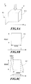
- the MRI image has each pixel thereof resulting from the projection of a cubic voxel 81 in the Z-direction.
- the projection of the voxel 81 should result in a square 811; thus, the X-direction resolution "resx" may have sharp edges.
- FIG. 8(C) when the slice/slab separation gradient 105 (as shown in FIG. 6 ) or 105 (as shown in FIG. 7 ) is turned on to separate two images, the projection, can present a parallelogram 812 as a result of some shear strain.
- the "resx" does not have sharp edges, causing the projected image to be blurred.
- res Z denotes the thickness of one slice
- res X denotes the resolution in the X-direction
- G Z denotes the slice-selection gradient
- G X denotes the frequency-encoding gradient
- the blur is required to be set in a preset range so that a sharp, unblurred image may be given.
- the preset blur can be set according to practical needs. For example, there is no change in the quality of image as the blur is less than 1 pixel, and therefore the image is of very good quality. The change is difficult to view from the naked eye as the blur is in the range of 1 ⁇ 3 pixels; making an image of good quality. When the blur is 3 pixels up to 6 pixels, the quality of image is of poor quality. When the blur is more than 6 pixels, the quality of the image is bad and many features become hard to determine. Nevertheless, adjustment may be made according to various needs since different blurs may find their uses in different situations.
- the resultant images of a SMA series gives inevitable blur due to the additional applied gradients, whereas the techniques described herein reduce the blur and therefore a sharp image of the slice/slab is acquired simultaneously.
- the RF pulse carrying at least two frequencies adopted in the present invention has the central frequencies, with respect to two adjacent slices, differing from each other by ( f sep ) 20 kHz or more.
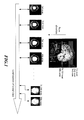
- FIG. 10(A) an embodiment is described in which 4 slices 401n through 404n of a subject are excited at a time and, as shown, an image of 12 slices are given through 3 series of excitations.
- Two adjacent slices 4011 and 4021 are those excited by the two frequencies carried by the RF pulse.
- FIG. 10(B) another embodiment of the present invention is described in which the RF pulse has multiple excitation frequencies and 4 slabs 501 through 504 of a subject are excited.
- each scan along the imaging direction can give 4 slice images when an RF pulse carrying 4 frequencies is used to excite 4 slices 401 through 404 of the subject, as shown in FIG. 10(A) .
- the Nth scan can give another 4 slice images 401N through 404N since those slices are simultaneously excited. Therefore, just N/4 scans can give N slice images.
- the methods described herein require only 64 scans for a total of 256 slice images.
- the time consumed for imaging can be cut down to one forth; in practice this embodiment decreases the time from about 54 minutes to about 14 minutes.
- a comparison is made with conventional processes in which a scan time Ta is required for exciting a whole slab 501 at a time to give the images of all the slices.
- a scan time Ta is required for exciting a whole slab 501 at a time to give the images of all the slices.
- an RF pulse carrying 4 frequencies can be used to excite the 4 slabs 501 through 504 of the subject. It requires only a scan time Tb /4 for acquiring the whole slab 501. Thus, the time required for acquiring all the images can be greatly decreased.
- an RF excitation signal 701 due to an RF excitation with 8 frequencies is distributed in the frequency domain, wherein the signal 701 is sent from the RF excitation module 21.
- a multi-slice MRI signal 702 with respect to the RF excitation signal 701 is distributed in the frequency domain, wherein the multi-slice MRI signal 702 is received by the RF receiving module 22.
- the received multi-slice MRI signal 702 is processed to give a MR image 703 that comprises the simultaneously acquired MRI signal from 8 slices.
Landscapes
- Physics & Mathematics (AREA)
- General Physics & Mathematics (AREA)
- High Energy & Nuclear Physics (AREA)
- Condensed Matter Physics & Semiconductors (AREA)
- Engineering & Computer Science (AREA)
- Signal Processing (AREA)
- Optics & Photonics (AREA)
- Spectroscopy & Molecular Physics (AREA)
- Nuclear Medicine, Radiotherapy & Molecular Imaging (AREA)
- Radiology & Medical Imaging (AREA)
- General Health & Medical Sciences (AREA)
- Health & Medical Sciences (AREA)
- Magnetic Resonance Imaging Apparatus (AREA)
Applications Claiming Priority (2)
| Application Number | Priority Date | Filing Date | Title |
|---|---|---|---|
| TW97116790 | 2008-05-07 | ||
| TW097130053A TWI366455B (en) | 2008-05-07 | 2008-08-07 | Method and apparatus for simultaneously acquiring multiple slices/slabs in magnetic resonance system |
Publications (2)
| Publication Number | Publication Date |
|---|---|
| EP2116859A2 true EP2116859A2 (de) | 2009-11-11 |
| EP2116859A3 EP2116859A3 (de) | 2010-10-20 |
Family
ID=40910872
Family Applications (1)
| Application Number | Title | Priority Date | Filing Date |
|---|---|---|---|
| EP09152666A Withdrawn EP2116859A3 (de) | 2008-05-07 | 2009-02-12 | Verfahren und Vorrichtung zum gleichzeitigen Erhalten mehrerer Schnitte/Scheiben in einem Kernspintomographiesystem |
Country Status (4)
| Country | Link |
|---|---|
| US (1) | US8022701B2 (de) |
| EP (1) | EP2116859A3 (de) |
| JP (1) | JP4944912B2 (de) |
| TW (1) | TWI366455B (de) |
Cited By (3)
| Publication number | Priority date | Publication date | Assignee | Title |
|---|---|---|---|---|
| WO2012088060A1 (en) * | 2010-12-20 | 2012-06-28 | Regents Of The University Of Minnesota | Method for rapid whole brain magnetic resonance imaging with contrast preparation |
| CN103083020A (zh) * | 2011-11-08 | 2013-05-08 | 三星电子株式会社 | 磁共振成像设备及其控制方法 |
| DE102012208019B3 (de) * | 2012-05-14 | 2013-10-31 | Universitätsklinikum Freiburg | Kernspintomographieverfahren mit einem Multiband-Hochfrequenzpuls mit mehreren separaten Frequenzbändern |
Families Citing this family (24)
| Publication number | Priority date | Publication date | Assignee | Title |
|---|---|---|---|---|
| US20110011102A1 (en) * | 2009-04-20 | 2011-01-20 | Erzhen Gao | Cryogenically cooled superconductor rf head coil array and head-only magnetic resonance imaging (mri) system using same |
| US8593141B1 (en) | 2009-11-24 | 2013-11-26 | Hypres, Inc. | Magnetic resonance system and method employing a digital squid |
| US8970217B1 (en) | 2010-04-14 | 2015-03-03 | Hypres, Inc. | System and method for noise reduction in magnetic resonance imaging |
| US8941381B2 (en) * | 2010-05-28 | 2015-01-27 | David Feinberg | Multiplicative increase in MRI data acquisition with multi-band RF excitation pulses in a simultaneous image refocusing pulse sequence |
| DE102010041191B4 (de) * | 2010-09-22 | 2016-02-18 | Siemens Aktiengesellschaft | Erstellung von MR-Bilddaten mit paralleler Schichtanregung und teilweiser Überlappung der Schichten im Frequenzbereich |
| US8692550B2 (en) * | 2011-03-17 | 2014-04-08 | National Taiwan University | Method and apparatus for acquiring magnetic resonance imaging signals |
| US8773128B2 (en) * | 2011-08-15 | 2014-07-08 | National Taiwan University | Method and apparatus for enhancing signal in magnetic resonance imaging |
| WO2013052535A1 (en) * | 2011-10-03 | 2013-04-11 | Regents Of The University Of Minnesota | System and method for reducing radio frequency peak voltage and power requirements in magnetic resonance imaging using time-shifted multiband radio frequency pulses |
| CN103185876B (zh) * | 2011-12-30 | 2015-05-13 | 西门子(深圳)磁共振有限公司 | 磁共振成像方法及磁共振成像装置 |
| DE102012212947B4 (de) | 2012-07-24 | 2014-06-26 | Siemens Aktiengesellschaft | Bearbeitung von mit Bildunschärfen behafteten MR-Bilddaten |
| CN103767705B (zh) | 2012-10-23 | 2017-12-22 | 三星电子株式会社 | 磁共振成像系统和磁共振成像方法 |
| KR102038627B1 (ko) * | 2012-10-23 | 2019-10-30 | 삼성전자주식회사 | 자기공명영상 시스템 및 자기공명영상 방법 |
| KR101967246B1 (ko) * | 2013-01-21 | 2019-04-09 | 삼성전자주식회사 | 자기공명영상 시스템, 데이터 처리장치 및 자기공명영상 생성 방법 |
| US9632157B2 (en) * | 2013-03-29 | 2017-04-25 | National Taiwan University | Method and apparatus for 3D magnetic resonance imaging |
| US9430706B1 (en) * | 2013-10-02 | 2016-08-30 | Given Imaging Ltd. | System and method for detection of in-vivo pathology sequences |
| KR20160029586A (ko) * | 2014-09-05 | 2016-03-15 | 삼성전자주식회사 | 자기 공명 영상 장치 및 그 동작방법 |
| KR102349449B1 (ko) | 2014-12-11 | 2022-01-10 | 삼성전자주식회사 | 자기 공명 영상 장치 및 자기 공명 영상 장치의 영상 처리 방법 |
| KR101802336B1 (ko) * | 2016-02-19 | 2017-11-28 | 삼성전자주식회사 | 다중 여기 rf 펄스를 이용한 자기공명영상 획득 방법 및 이를 위한 자기공명영상 장치 |
| US10185016B2 (en) | 2016-04-22 | 2019-01-22 | General Electric Company | System and method for imaging four-dimensional flow of a fluid within a volume of an imaged object |
| US10420510B2 (en) | 2016-04-22 | 2019-09-24 | General Electric Company | System and method for imaging a moving subject |
| KR101974199B1 (ko) * | 2017-03-21 | 2019-04-30 | 한국과학기술원 | 가변절편 자기공명영상 데이터 획득방법 |
| KR102001874B1 (ko) * | 2018-01-05 | 2019-07-19 | 한국과학기술원 | 고정 rf 코일과 자유이동 rf 코일의 조합을 이용하여 mri 이미지의 snr을 실시간으로 향상하는 방법 및 이를 이용한 mri 데이터 처리장치 |
| CN110604571B (zh) * | 2019-09-12 | 2021-07-20 | 中国科学院武汉物理与数学研究所 | 一种分段编码的双核同步磁共振成像方法 |
| CN119477699B (zh) * | 2025-01-15 | 2025-05-09 | 大连海事大学 | 基于频域感知状态空间模型的前列腺mri超分辨率重建方法 |
Family Cites Families (7)
| Publication number | Priority date | Publication date | Assignee | Title |
|---|---|---|---|---|
| JP3161750B2 (ja) * | 1991-06-05 | 2001-04-25 | 株式会社日立製作所 | 磁気共鳴診断装置および画像データ処理方法 |
| JP3162444B2 (ja) * | 1991-11-28 | 2001-04-25 | 株式会社東芝 | 磁気共鳴診断装置 |
| US5786692A (en) * | 1995-08-18 | 1998-07-28 | Brigham And Women's Hospital, Inc. | Line scan diffusion imaging |
| US6486669B1 (en) * | 1999-05-14 | 2002-11-26 | Koninklijke Philips Electronics N.V. | MR elastography method |
| DE10152734B4 (de) * | 2001-10-25 | 2005-12-29 | Siemens Ag | Gerät und Verfahren zur Magnet-Resonanz-Bildgebung bei gleichzeitiger Messung zweier benachbarter Schichten |
| US6980001B2 (en) * | 2002-05-20 | 2005-12-27 | The University Of Sheffield At Western Bank | Methods & apparatus for magnetic resonance imaging |
| JP5063279B2 (ja) * | 2007-09-27 | 2012-10-31 | 株式会社日立製作所 | 磁気共鳴装置 |
-
2008
- 2008-08-07 TW TW097130053A patent/TWI366455B/zh not_active IP Right Cessation
- 2008-12-17 US US12/337,388 patent/US8022701B2/en active Active
-
2009
- 2009-02-12 EP EP09152666A patent/EP2116859A3/de not_active Withdrawn
- 2009-03-09 JP JP2009054823A patent/JP4944912B2/ja not_active Expired - Fee Related
Non-Patent Citations (4)
| Title |
|---|
| BRIAN A. HARGREAVES ET AL: "Independent phase modulation for efficient dual-band 3D imaging", MAGNETIC RESONANCE IN MEDICINE, vol. 57, no. 4, 1 January 2007 (2007-01-01), pages 798 - 802, XP055068756, ISSN: 0740-3194, DOI: 10.1002/mrm.21180 * |
| GLYN JOHNSON ET AL: "2D Multislice and 3D MRI Sequences Are Often Equally Sensitive", MAGNETIC RESONANCE IN MEDICINE, vol. 41, no. 4, 1 April 1999 (1999-04-01), pages 824 - 828, XP055068860 * |
| OSHIO K ET AL: "T2-WEIGHTED THIN-SECTION IMAGING WITH THE MULTISLAB THREE-DIMENSIONAL RARE TECHNIQUE", JOURNAL OF MAGNETIC RESONANCE IMAGING, SOCIETY FOR MAGNETIC RESONANCE IMAGING, OAK BROOK, IL, US, vol. 1, no. 6, 11 December 1991 (1991-12-11), pages 695 - 700, XP000567313, ISSN: 1053-1807 * |
| PARKER D L ET AL: "MR ANGIOGRAPHY BY MULTIPLE THIN SLAB 3D ACQUISITION", MAGNETIC RESONANCE IN MEDICINE, ACADEMIC PRESS, DULUTH, MN, US, vol. 17, no. 2, 1 February 1991 (1991-02-01), pages 434 - 451, XP000203282, ISSN: 0740-3194 * |
Cited By (6)
| Publication number | Priority date | Publication date | Assignee | Title |
|---|---|---|---|---|
| WO2012088060A1 (en) * | 2010-12-20 | 2012-06-28 | Regents Of The University Of Minnesota | Method for rapid whole brain magnetic resonance imaging with contrast preparation |
| US9915717B2 (en) | 2010-12-20 | 2018-03-13 | Regents Of The University Of Minnesota | Method for rapid whole brain magnetic resonance imaging with contrast preparation |
| CN103083020A (zh) * | 2011-11-08 | 2013-05-08 | 三星电子株式会社 | 磁共振成像设备及其控制方法 |
| US9291693B2 (en) | 2011-11-08 | 2016-03-22 | Samsung Electronics Co., Ltd. | Magnetic resonance imaging apparatus and control method thereof |
| DE102012208019B3 (de) * | 2012-05-14 | 2013-10-31 | Universitätsklinikum Freiburg | Kernspintomographieverfahren mit einem Multiband-Hochfrequenzpuls mit mehreren separaten Frequenzbändern |
| WO2013171119A1 (de) * | 2012-05-14 | 2013-11-21 | Universitätsklinikum Freiburg | Kernspintomographieverfahren |
Also Published As
| Publication number | Publication date |
|---|---|
| JP2009268891A (ja) | 2009-11-19 |
| TWI366455B (en) | 2012-06-21 |
| US8022701B2 (en) | 2011-09-20 |
| EP2116859A3 (de) | 2010-10-20 |
| TW200946079A (en) | 2009-11-16 |
| US20090278538A1 (en) | 2009-11-12 |
| JP4944912B2 (ja) | 2012-06-06 |
Similar Documents
| Publication | Publication Date | Title |
|---|---|---|
| US8022701B2 (en) | Method and apparatus for simultaneously acquiring multiple slices/slabs in magnetic resonance system | |
| EP0529527B1 (de) | Verfahren und Apparat für schnelle Bilderzeugung mit verbesserter Bildqualität mittels magnetischer Resonanz | |
| US8076935B2 (en) | Magnetic resonance imaging (MRI) using SPIR and/or chess suppression pulses | |
| US8093895B2 (en) | Magnetic resonance imaging apparatus and magnetic resonance imaging method of controlling image contrast | |
| DE19821780B4 (de) | Korrektur von durch Maxwell-Terme bei einer Schnitt-Verschiebungs-Echo-Planar-Abbildung verursachten Artefakten | |
| EP2193385B1 (de) | Magnetresonanz unter verwendung von mehrdimensionalen rf-erregungsimpulsen | |
| DE102010041212B4 (de) | Kompensation von Echozeit-unabhängigen Phasen- oder Magnitudenanteilen in aufgenommenen MR-Bilddaten | |
| CN107072586B (zh) | 磁共振成像装置 | |
| US8466679B2 (en) | Magnetic resonance imaging apparatus and method configured for susceptibility-emphasized imaging with improved signal-to-noise ratio | |
| JP6328623B2 (ja) | 改善された磁気共鳴収集のための方法およびシステム | |
| JP6762284B2 (ja) | 磁気共鳴イメージング装置およびノイズ除去方法 | |
| US5499629A (en) | Slice profile stabilization for segmented k-space magnetic resonance imaging | |
| US5528145A (en) | High-speed magnetic resonance imaging method | |
| US8692550B2 (en) | Method and apparatus for acquiring magnetic resonance imaging signals | |
| US11327135B2 (en) | Artificial intelligence based suppression of chemical species in magnetic resonance imaging | |
| US4703268A (en) | Clean multiple echo magnetic resonance imaging using asymmetric sequences | |
| US8773128B2 (en) | Method and apparatus for enhancing signal in magnetic resonance imaging | |
| CN101676737B (zh) | 多截面/区块磁共振讯号的控制方法及系统 | |
| JP2000300535A5 (ja) | 温度計測方法及び磁気共鳴イメージング装置 | |
| WO2021247857A1 (en) | System and methods for ultra-fast multi-dimensional diffusion-relaxation mri using time-division multiplexing sequences | |
| EP2784531B1 (de) | Verfahren und Vorrichtung zur 3D-Magnetresonanzbildgebung | |
| US20030210044A1 (en) | Missing pulse steady state free precession | |
| JP2001008919A (ja) | 磁気共鳴撮影装置及びケミカルシフト情報処理方法 | |
| TWI529405B (zh) | 取得磁共振影像訊號方法及裝置 | |
| JPH0716217A (ja) | 磁気共鳴イメージング方法及びその装置 |
Legal Events
| Date | Code | Title | Description |
|---|---|---|---|
| PUAI | Public reference made under article 153(3) epc to a published international application that has entered the european phase |
Free format text: ORIGINAL CODE: 0009012 |
|
| AK | Designated contracting states |
Kind code of ref document: A2 Designated state(s): AT BE BG CH CY CZ DE DK EE ES FI FR GB GR HR HU IE IS IT LI LT LU LV MC MK MT NL NO PL PT RO SE SI SK TR |
|
| AX | Request for extension of the european patent |
Extension state: AL BA RS |
|
| RAP1 | Party data changed (applicant data changed or rights of an application transferred) |
Owner name: NATIONAL TAIWAN UNIVERSITY |
|
| PUAL | Search report despatched |
Free format text: ORIGINAL CODE: 0009013 |
|
| AK | Designated contracting states |
Kind code of ref document: A3 Designated state(s): AT BE BG CH CY CZ DE DK EE ES FI FR GB GR HR HU IE IS IT LI LT LU LV MC MK MT NL NO PL PT RO SE SI SK TR |
|
| AX | Request for extension of the european patent |
Extension state: AL BA RS |
|
| 17P | Request for examination filed |
Effective date: 20110420 |
|
| AKX | Designation fees paid |
Designated state(s): AT BE BG CH CY CZ DE DK EE ES FI FR GB GR HR HU IE IS IT LI LT LU LV MC MK MT NL NO PL PT RO SE SI SK TR |
|
| 17Q | First examination report despatched |
Effective date: 20111214 |
|
| APBK | Appeal reference recorded |
Free format text: ORIGINAL CODE: EPIDOSNREFNE |
|
| APBN | Date of receipt of notice of appeal recorded |
Free format text: ORIGINAL CODE: EPIDOSNNOA2E |
|
| APBR | Date of receipt of statement of grounds of appeal recorded |
Free format text: ORIGINAL CODE: EPIDOSNNOA3E |
|
| APAF | Appeal reference modified |
Free format text: ORIGINAL CODE: EPIDOSCREFNE |
|
| APBT | Appeal procedure closed |
Free format text: ORIGINAL CODE: EPIDOSNNOA9E |
|
| STAA | Information on the status of an ep patent application or granted ep patent |
Free format text: STATUS: THE APPLICATION IS DEEMED TO BE WITHDRAWN |
|
| 18D | Application deemed to be withdrawn |
Effective date: 20190903 |