EP2117101A1 - Integrierter elektrischer verdichter - Google Patents
Integrierter elektrischer verdichter Download PDFInfo
- Publication number
- EP2117101A1 EP2117101A1 EP07828839A EP07828839A EP2117101A1 EP 2117101 A1 EP2117101 A1 EP 2117101A1 EP 07828839 A EP07828839 A EP 07828839A EP 07828839 A EP07828839 A EP 07828839A EP 2117101 A1 EP2117101 A1 EP 2117101A1
- Authority
- EP
- European Patent Office
- Prior art keywords
- board
- electric compressor
- motor
- capacitor
- integrated electric
- Prior art date
- Legal status (The legal status is an assumption and is not a legal conclusion. Google has not performed a legal analysis and makes no representation as to the accuracy of the status listed.)
- Granted
Links
- 239000003990 capacitor Substances 0.000 claims abstract description 34
- 230000001603 reducing effect Effects 0.000 abstract description 5
- WABPQHHGFIMREM-UHFFFAOYSA-N lead(0) Chemical compound [Pb] WABPQHHGFIMREM-UHFFFAOYSA-N 0.000 description 7
- 230000003247 decreasing effect Effects 0.000 description 5
- 230000004308 accommodation Effects 0.000 description 3
- 238000010276 construction Methods 0.000 description 3
- 238000010586 diagram Methods 0.000 description 3
- 230000000452 restraining effect Effects 0.000 description 2
- 239000004020 conductor Substances 0.000 description 1
- 230000000694 effects Effects 0.000 description 1
- 238000009499 grossing Methods 0.000 description 1
- 230000007257 malfunction Effects 0.000 description 1
Images



Classifications
-
- F—MECHANICAL ENGINEERING; LIGHTING; HEATING; WEAPONS; BLASTING
- F04—POSITIVE - DISPLACEMENT MACHINES FOR LIQUIDS; PUMPS FOR LIQUIDS OR ELASTIC FLUIDS
- F04B—POSITIVE-DISPLACEMENT MACHINES FOR LIQUIDS; PUMPS
- F04B35/00—Piston pumps specially adapted for elastic fluids and characterised by the driving means to their working members, or by combination with, or adaptation to, specific driving engines or motors, not otherwise provided for
- F04B35/04—Piston pumps specially adapted for elastic fluids and characterised by the driving means to their working members, or by combination with, or adaptation to, specific driving engines or motors, not otherwise provided for the means being electric
-
- F—MECHANICAL ENGINEERING; LIGHTING; HEATING; WEAPONS; BLASTING
- F04—POSITIVE - DISPLACEMENT MACHINES FOR LIQUIDS; PUMPS FOR LIQUIDS OR ELASTIC FLUIDS
- F04B—POSITIVE-DISPLACEMENT MACHINES FOR LIQUIDS; PUMPS
- F04B39/00—Component parts, details, or accessories, of pumps or pumping systems specially adapted for elastic fluids, not otherwise provided for in, or of interest apart from, groups F04B25/00 - F04B37/00
- F04B39/12—Casings; Cylinders; Cylinder heads; Fluid connections
- F04B39/121—Casings
-
- H—ELECTRICITY
- H02—GENERATION; CONVERSION OR DISTRIBUTION OF ELECTRIC POWER
- H02K—DYNAMO-ELECTRIC MACHINES
- H02K11/00—Structural association of dynamo-electric machines with electric components or with devices for shielding, monitoring or protection
- H02K11/01—Structural association of dynamo-electric machines with electric components or with devices for shielding, monitoring or protection for shielding from electromagnetic fields, i.e. structural association with shields
- H02K11/014—Shields associated with stationary parts, e.g. stator cores
- H02K11/0141—Shields associated with casings, enclosures or brackets
-
- H—ELECTRICITY
- H02—GENERATION; CONVERSION OR DISTRIBUTION OF ELECTRIC POWER
- H02K—DYNAMO-ELECTRIC MACHINES
- H02K11/00—Structural association of dynamo-electric machines with electric components or with devices for shielding, monitoring or protection
- H02K11/04—Structural association of dynamo-electric machines with electric components or with devices for shielding, monitoring or protection for rectification
- H02K11/049—Rectifiers associated with stationary parts, e.g. stator cores
- H02K11/05—Rectifiers associated with casings, enclosures or brackets
-
- H—ELECTRICITY
- H02—GENERATION; CONVERSION OR DISTRIBUTION OF ELECTRIC POWER
- H02K—DYNAMO-ELECTRIC MACHINES
- H02K11/00—Structural association of dynamo-electric machines with electric components or with devices for shielding, monitoring or protection
- H02K11/30—Structural association with control circuits or drive circuits
- H02K11/33—Drive circuits, e.g. power electronics
-
- H—ELECTRICITY
- H02—GENERATION; CONVERSION OR DISTRIBUTION OF ELECTRIC POWER
- H02P—CONTROL OR REGULATION OF ELECTRIC MOTORS, ELECTRIC GENERATORS OR DYNAMO-ELECTRIC CONVERTERS; CONTROLLING TRANSFORMERS, REACTORS OR CHOKE COILS
- H02P27/00—Arrangements or methods for the control of AC motors characterised by the kind of supply voltage
- H02P27/04—Arrangements or methods for the control of AC motors characterised by the kind of supply voltage using variable-frequency supply voltage, e.g. inverter or converter supply voltage
- H02P27/06—Arrangements or methods for the control of AC motors characterised by the kind of supply voltage using variable-frequency supply voltage, e.g. inverter or converter supply voltage using DC to AC converters or inverters
-
- F—MECHANICAL ENGINEERING; LIGHTING; HEATING; WEAPONS; BLASTING
- F04—POSITIVE - DISPLACEMENT MACHINES FOR LIQUIDS; PUMPS FOR LIQUIDS OR ELASTIC FLUIDS
- F04B—POSITIVE-DISPLACEMENT MACHINES FOR LIQUIDS; PUMPS
- F04B2203/00—Motor parameters
- F04B2203/02—Motor parameters of rotating electric motors
- F04B2203/0204—Frequency of the electric current
-
- H—ELECTRICITY
- H02—GENERATION; CONVERSION OR DISTRIBUTION OF ELECTRIC POWER
- H02K—DYNAMO-ELECTRIC MACHINES
- H02K11/00—Structural association of dynamo-electric machines with electric components or with devices for shielding, monitoring or protection
- H02K11/02—Structural association of dynamo-electric machines with electric components or with devices for shielding, monitoring or protection for suppression of electromagnetic interference
- H02K11/026—Suppressors associated with brushes, brush holders or their supports
-
- H—ELECTRICITY
- H02—GENERATION; CONVERSION OR DISTRIBUTION OF ELECTRIC POWER
- H02K—DYNAMO-ELECTRIC MACHINES
- H02K11/00—Structural association of dynamo-electric machines with electric components or with devices for shielding, monitoring or protection
- H02K11/02—Structural association of dynamo-electric machines with electric components or with devices for shielding, monitoring or protection for suppression of electromagnetic interference
- H02K11/028—Suppressors associated with the rotor
-
- H—ELECTRICITY
- H02—GENERATION; CONVERSION OR DISTRIBUTION OF ELECTRIC POWER
- H02M—APPARATUS FOR CONVERSION BETWEEN AC AND AC, BETWEEN AC AND DC, OR BETWEEN DC AND DC, AND FOR USE WITH MAINS OR SIMILAR POWER SUPPLY SYSTEMS; CONVERSION OF DC OR AC INPUT POWER INTO SURGE OUTPUT POWER; CONTROL OR REGULATION THEREOF
- H02M7/00—Conversion of AC power input into DC power output; Conversion of DC power input into AC power output
- H02M7/003—Constructional details, e.g. physical layout, assembly, wiring or busbar connections
Definitions
- the present invention relates to an integrated electric compressor constituting an on-vehicle air conditioner.
- an on-vehicle air conditioner space saving is required to accommodate pieces of equipment in a vehicular engine room.
- an integrated electric compressor in which a compressor constituting the on-vehicle air conditioner, a motor for driving the compressor, and a driving board for driving the motor are integrally accommodated in a housing.
- the common mode capacitors 2 and the common mode coil 3 each have a large part size. Since on-vehicle equipment including the electric compressor is always required to be downsized, further improvement is desired from this point of view. Also, the large part size restricts the arrangement of these parts in the housing, which also hinders the downsizing.
- a lead wire (electric wire) 7 is used for wiring between driving board 1 and these parts.
- the fluctuations in power supply voltage caused by the switching action of the driving board 1 increase, and an influence on radio noise increases.
- the leakage current flowing from the motor 5 to the housing generates a high-frequency component due to surge caused especially when the current is turned off, so that the reduction in radio noise at this time is especially desired.
- the present invention has been made to solve the above technical problems, and accordingly an object thereof is to provide an integrated electric compressor that can be made small in size while reducing radio noise effectively.
- An integrated electric compressor of the present invention made to achieve the above object comprises a compressor constituting an air conditioner; a motor driving the compressor; a control board controlling the operation of the motor; and a housing accommodating the compressor, the motor, and the control board.
- the control board is characterized by comprising a switching element controlling the application of a voltage to the motor from a power source to rotationally drive the motor; a control circuit controlling the operation of the switching element; and a snubber circuit which is provided between the power source and the switching element to reduce radio noise and comprises a resistor and a capacitor.
- the resistor and the capacitor constituting the snubber circuit are preferably surface mounted on a first board.
- control circuit be mounted on a second board arranged so as to face to the first board with a space being provided therebetween, and the snubber circuit be mounted on the first board on the surface opposite to the side facing the second board.
- power wiring for applying a voltage from the power source to the first board is preferably formed by a bus bar.
- the present invention can be applied especially effectively.
- the snubber circuit is provided in the circuit for driving the motor of the integrated electric compressor, radio noise can be reduced. Since the snubber circuit can be made a surface mounting part, the leakage current is reduced, and the size of a closed loop formed by the leakage current is decreased, which is especially effective in reducing radio noise. Also, by making the snubber circuit a surface mounting part, the size of the integrated electric compressor can be decreased.
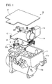
- Figure 1 is a view showing a configuration of an electric compressor (integrated electric compressor) 10 of this embodiment.
- a motor (not shown) and a scroll compressor (not shown) are accommodated in a lower accommodation chamber 11a of a housing 11, and an inverter board (control board) 12 is accommodated in an upper accommodation chamber 11b, which is open upward, of the housing 11.
- the upward opening of the upper accommodation chamber 11b is covered with a cover 17.
- the inverter board 12 comprises a capacitor 13 and an inductor 14, which are used for smoothing a dc voltage supplied to the inverter board 12, a control circuit board (control circuit, second board) 15 for controlling the application of a high-voltage alternating current to the motor, and a power board (first board) 16 for converting a direct current supplied from a high-voltage power source into an alternating current and applying the alternating current to the motor to rotationally drive the motor.
- FIG. 2 is a diagram showing a circuit configuration of the power board 16.
- a high voltage for example, as high as 300 V is supplied from an external high-voltage power source (not shown).
- a switching element 18 formed by a plurality of IGBTs is mounted on the power board 16.
- a microcomputer for controlling the operation of the switching element 18 and a gate circuit are provided on the control circuit board 15, a microcomputer for controlling the operation of the switching element 18 and a gate circuit (both of the two not shown) are provided.
- the gate circuit is driven by the control of the microcomputer, and the drive signal thereof is transmitted from the control circuit board 15 to the power board 16 and is input to the switching element 18, by which the switching element 18 is operated.
- the high voltage supplied from the high-voltage power source is applied to a motor 19 of the electric compressor 10 as a three-phase alternating current, by which the motor 19 is rotationally driven.
- a snubber circuit 21 comprising a resistor R and a capacitor C is provided between input/output terminals 20 of the power source and the switching element 18.
- the snubber circuit 21 is originally used for protecting the switching element 18 from overvoltage, and when the power source is off, the snubber circuit 21 consumes a surge occurring as the frequency of a drive signal sent from the control circuit board 15 to the switching element 18 increases.
- a high-frequency component can be made such as not to be included in the drive signal sent from the control circuit board 15 to the switching element 18.
- a leakage current produced between the motor 19 and the housing 11 can be restrained, and radio noise can be reduced.
- the snubber circuit 21 is configured by surface mounting resistive elements 21r constituting the resistor R and a capacitor element 21c constituting the capacitor C on the power board 16. In the snubber circuit 21, since the capacitor capacity of the capacitor element 21c can be decreased, the surface mounting type snubber circuit 21 is realistic.
- resistive elements 21r and the capacitor element 21c are surface mounted on the power board 16, a space for providing a common mode capacitor and a common mode coil is substantially unnecessary as compared with the case where the conventional common mode capacitor and common mode coil are used, so that the size of the electric compressor 10 can be decreased.
- the connection to the common mode capacitor and the common mode coil has conventionally been made by using a lead wire.
- the resistive elements 21r and the capacitor element 21c constituting the snubber circuit 21 are surface mounted on the power board 16, the resistive elements 21r and the capacitor element 21c naturally do not require a lead wire, so that the floating inductance can be reduced. Thereby, the radio noise reducing effect is further increased.
- the resistive elements 21r and the capacitor element 21c constituting the snubber circuit 21 are surface mounted on the power board 16, a closed loop of current formed by a leakage current produced by a floating capacity Cf' between the motor 19 and the housing 11 flows in the resistive elements 21r and the capacitor element 21c on the power board 16. That is to say, the closed loop formed by the leakage current does not extend to the outside from the power board 16, and is completed by between the power board 16 and the housing 11. The fact that the closed loop itself formed by the leakage current can be decreased contributes greatly to the reduction in radio noise.
- the snubber circuit 21 having a leakage current restraining effect is provided, the leakage current is restrained, and radio noise is reduced. Further, since the snubber circuit 21 is surface mounted on the power board 16, the radio noise reducing effect is further remarkable.
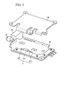
- control circuit board 15 and the power board 16 are provided so as to face to each other with a space being provided therebetween. Also, as shown in Figure 3 , the power board 16 is provided with a heat radiating plate 30 for radiating heat of the switching element 18.
- the resistive elements 21r and the capacitor element 21c constituting the snubber circuit 21 and the switching element 18 are preferably surface mounted on the power board 16 on the side opposite to the side on which the control circuit board 15 is arranged.
- a surface (layer) 22 having low impedance which is formed of a conductive material, such as a power frame, a GND frame, or a GND layer, provided in the power board 16, an effect of shielding noise generated by the switching element 18 and the like is achieved, and an influence on the control circuit board 15 is restrained. Since the control circuit board 15 is provided with a digital circuit such as a microcomputer driven by a low voltage, by restraining noise from the switching element 18, malfunction of the microcomputer and the like can be prevented.
- the input/output terminals 20 comprises pin-shaped PN terminals 20a and 20b mounted on the power board 16.
- the electrical continuity to the PN terminals 20a and 20b is made by the connection of bus bars 23 and 24 from the high-voltage power source side.
- connection using the bus bars 23 and 24 is used for power wiring for applying a power supply voltage to the power board 16, the impedance of the power wiring can be reduced significantly as compared with the case where a lead wire is used. As a result, the fluctuations in the power supply voltage can be restrained, which contributes to the reduction in radio noise.
- the impedance of the power wiring increases. Therefore, in the conventional construction, since the sizes of the common mode capacitor and common mode coil are large, the arrangement thereof is restricted, and the length of lead wire for power wiring increases resultantly.
- An advantage of the construction using the bus bars 23 and 24 of this embodiment is enormous as compared with such the conventional case.
- the leakage current from the motor 19 is restrained and radio noise is reduced, and further the size of the electric compressor 10 can be reduced.
Landscapes
- Engineering & Computer Science (AREA)
- Power Engineering (AREA)
- Mechanical Engineering (AREA)
- General Engineering & Computer Science (AREA)
- Microelectronics & Electronic Packaging (AREA)
- Physics & Mathematics (AREA)
- Electromagnetism (AREA)
- Compressor (AREA)
- Inverter Devices (AREA)
- Control Of Positive-Displacement Pumps (AREA)
- Control Of Ac Motors In General (AREA)
Applications Claiming Priority (2)
| Application Number | Priority Date | Filing Date | Title |
|---|---|---|---|
| JP2007051665A JP4981483B2 (ja) | 2007-03-01 | 2007-03-01 | 一体型電動圧縮機 |
| PCT/JP2007/069098 WO2008108022A1 (ja) | 2007-03-01 | 2007-09-28 | 一体型電動圧縮機 |
Publications (3)
| Publication Number | Publication Date |
|---|---|
| EP2117101A1 true EP2117101A1 (de) | 2009-11-11 |
| EP2117101A4 EP2117101A4 (de) | 2016-12-21 |
| EP2117101B1 EP2117101B1 (de) | 2017-11-29 |
Family
ID=39737923
Family Applications (1)
| Application Number | Title | Priority Date | Filing Date |
|---|---|---|---|
| EP07828839.6A Not-in-force EP2117101B1 (de) | 2007-03-01 | 2007-09-28 | Integrierter elektrischer verdichter |
Country Status (4)
| Country | Link |
|---|---|
| US (1) | US9909578B2 (de) |
| EP (1) | EP2117101B1 (de) |
| JP (1) | JP4981483B2 (de) |
| WO (1) | WO2008108022A1 (de) |
Cited By (2)
| Publication number | Priority date | Publication date | Assignee | Title |
|---|---|---|---|---|
| EP2131481A4 (de) * | 2007-03-29 | 2013-07-31 | Mitsubishi Heavy Ind Ltd | Elektrischer einmodell-kompressor |
| CN106341069A (zh) * | 2015-07-07 | 2017-01-18 | 株式会社丰田自动织机 | 车载用的逆变器装置以及车载用的电动压缩机 |
Families Citing this family (7)
| Publication number | Priority date | Publication date | Assignee | Title |
|---|---|---|---|---|
| JP5107114B2 (ja) * | 2008-03-28 | 2012-12-26 | 三菱重工業株式会社 | インバータ一体型電動圧縮機 |
| JP5393324B2 (ja) * | 2009-07-30 | 2014-01-22 | 三菱重工業株式会社 | インバータ一体型電動圧縮機 |
| US20120308414A1 (en) * | 2010-09-16 | 2012-12-06 | Panasonic Corporation | Inverter-integrated electric compressor |
| KR102257795B1 (ko) * | 2014-08-29 | 2021-05-28 | 한온시스템 주식회사 | 전동 압축기 |
| JP6399602B2 (ja) | 2015-03-23 | 2018-10-03 | 三菱重工サーマルシステムズ株式会社 | 電力変換用回路基板及び電動圧縮機 |
| WO2022107810A1 (ja) | 2020-11-19 | 2022-05-27 | サンデン・アドバンストテクノロジー株式会社 | インバータ一体型電動圧縮機 |
| JP7692446B2 (ja) * | 2023-03-22 | 2025-06-13 | ダイキン工業株式会社 | 電力変換装置 |
Family Cites Families (24)
| Publication number | Priority date | Publication date | Assignee | Title |
|---|---|---|---|---|
| US4371824A (en) * | 1979-07-05 | 1983-02-01 | Eaton Corporation | Base drive and overlap protection circuit |
| US4358730A (en) * | 1981-06-19 | 1982-11-09 | Essex Group, Inc. | AC Power control circuit |
| US4575668A (en) * | 1984-07-09 | 1986-03-11 | Liebert Corporation | Controller for providing PWM drive to an A.C. motor |
| JPH02250410A (ja) * | 1989-03-24 | 1990-10-08 | Tamagawa Seiki Co Ltd | フィルタ回路 |
| US4990057A (en) * | 1989-05-03 | 1991-02-05 | Johnson Service Company | Electronic control for monitoring status of a compressor |
| US5013990A (en) * | 1989-10-16 | 1991-05-07 | Weber Harold J | Energy conserving electric motor power control method and apparatus |
| JP2856962B2 (ja) * | 1991-10-14 | 1999-02-10 | オークマ株式会社 | パワー配線基板 |
| JPH09214276A (ja) * | 1996-02-05 | 1997-08-15 | Tohoku Ricoh Co Ltd | ノイズフィルタ |
| JP4142227B2 (ja) * | 2000-01-28 | 2008-09-03 | サンデン株式会社 | 車両用電動圧縮機のモータ駆動用インバータ装置 |
| JP3584847B2 (ja) * | 2000-04-03 | 2004-11-04 | ダイキン工業株式会社 | 空気調和機 |
| JP2001359280A (ja) * | 2000-06-14 | 2001-12-26 | Origin Electric Co Ltd | 電源装置 |
| JP2002081712A (ja) | 2000-09-08 | 2002-03-22 | Hitachi Ltd | 空気調和機 |
| US6738239B2 (en) * | 2001-02-26 | 2004-05-18 | Woodward Governor Company | Active snubber circuit for electrical rotary actuator |
| JP2002291260A (ja) * | 2001-03-26 | 2002-10-04 | Mitsubishi Electric Corp | モータ制御装置及びこれを用いた圧縮機 |
| JP2003319665A (ja) * | 2002-04-19 | 2003-11-07 | Toyota Motor Corp | 電力変換装置 |
| JP4722372B2 (ja) * | 2002-10-11 | 2011-07-13 | ダイキン工業株式会社 | 相電流検出装置 |
| JP2004274911A (ja) * | 2003-03-10 | 2004-09-30 | Denso Corp | モータ駆動装置 |
| JP2004308445A (ja) * | 2003-04-02 | 2004-11-04 | Denso Corp | 電動圧縮機 |
| JP2005161940A (ja) * | 2003-12-01 | 2005-06-23 | Denso Corp | 自動車用空調装置 |
| US20050162140A1 (en) * | 2004-01-23 | 2005-07-28 | Mark Hirst | Apparatus including switching circuit |
| JP2005218256A (ja) * | 2004-01-30 | 2005-08-11 | Mitsubishi Electric Corp | 車載用電力変換装置 |
| JP2006027315A (ja) * | 2004-07-12 | 2006-02-02 | Denso Corp | モータ駆動回路一体型電動圧縮機 |
| US7429842B2 (en) * | 2005-02-04 | 2008-09-30 | Alan M. Schulman | Control and alarm system for sump pump |
| JP5091521B2 (ja) * | 2007-03-29 | 2012-12-05 | 三菱重工業株式会社 | 一体型電動圧縮機 |
-
2007
- 2007-03-01 JP JP2007051665A patent/JP4981483B2/ja not_active Expired - Fee Related
- 2007-09-28 US US12/439,593 patent/US9909578B2/en active Active
- 2007-09-28 EP EP07828839.6A patent/EP2117101B1/de not_active Not-in-force
- 2007-09-28 WO PCT/JP2007/069098 patent/WO2008108022A1/ja not_active Ceased
Non-Patent Citations (1)
| Title |
|---|
| See references of WO2008108022A1 * |
Cited By (3)
| Publication number | Priority date | Publication date | Assignee | Title |
|---|---|---|---|---|
| EP2131481A4 (de) * | 2007-03-29 | 2013-07-31 | Mitsubishi Heavy Ind Ltd | Elektrischer einmodell-kompressor |
| CN106341069A (zh) * | 2015-07-07 | 2017-01-18 | 株式会社丰田自动织机 | 车载用的逆变器装置以及车载用的电动压缩机 |
| CN106341069B (zh) * | 2015-07-07 | 2019-05-28 | 株式会社丰田自动织机 | 车载用的逆变器装置以及车载用的电动压缩机 |
Also Published As
| Publication number | Publication date |
|---|---|
| EP2117101B1 (de) | 2017-11-29 |
| US9909578B2 (en) | 2018-03-06 |
| EP2117101A4 (de) | 2016-12-21 |
| US20090291002A1 (en) | 2009-11-26 |
| WO2008108022A1 (ja) | 2008-09-12 |
| JP4981483B2 (ja) | 2012-07-18 |
| JP2008220005A (ja) | 2008-09-18 |
Similar Documents
| Publication | Publication Date | Title |
|---|---|---|
| US8308442B2 (en) | Integrated electric compressor | |
| EP2117101B1 (de) | Integrierter elektrischer verdichter | |
| JP5199698B2 (ja) | 一体型電動圧縮機 | |
| US8257060B2 (en) | Inverter-integrated electric compressor | |
| JP5039356B2 (ja) | 制御基板および電動圧縮機の制御装置ならびに電動圧縮機 | |
| JP6230946B2 (ja) | 電力変換装置、およびそれを搭載した鉄道車両 | |
| CN108369863B (zh) | 电力转换装置 | |
| CN1101895C (zh) | 压缩机驱动装置 | |
| US20240274346A1 (en) | Surface-mounted magnetic-component module | |
| CN108474569A (zh) | 空调机的室外机 | |
| KR101701553B1 (ko) | 전동 압축기용 인버터 모듈 | |
| US20120307468A1 (en) | Electronic apparatus | |
| EP3796554B1 (de) | Rauschfilter | |
| CN115516762B (zh) | 滤波装置及电力变换装置 | |
| CN111095763B (zh) | 电子控制装置 | |
| KR101776213B1 (ko) | 냉각팬 제어기를 위한 emi 저감 장치 | |
| JP7095711B2 (ja) | スイッチング電源装置 | |
| JP2008263675A (ja) | パワー半導体素子の駆動回路及びパワー半導体素子回路 | |
| CN114208016B (zh) | 电力转换装置 | |
| EP4683435A1 (de) | Elektrische schaltung mit einer bypass-komponente zur reduzierung elektromagnetischer emission | |
| CN120110261A (zh) | 用于电机的逆变器控制单元的连接模块和用于逆变器控制单元的连接系统 | |
| US20090108434A1 (en) | Semiconductor integrated circuit device, pdp driver, and plasma display panel | |
| JP2020014374A (ja) | 電力変換用回路基板及び電動圧縮機 | |
| JP2004350376A (ja) | 負荷一体型駆動装置 |
Legal Events
| Date | Code | Title | Description |
|---|---|---|---|
| PUAI | Public reference made under article 153(3) epc to a published international application that has entered the european phase |
Free format text: ORIGINAL CODE: 0009012 |
|
| 17P | Request for examination filed |
Effective date: 20090720 |
|
| AK | Designated contracting states |
Kind code of ref document: A1 Designated state(s): AT BE BG CH CY CZ DE DK EE ES FI FR GB GR HU IE IS IT LI LT LU LV MC MT NL PL PT RO SE SI SK TR |
|
| DAX | Request for extension of the european patent (deleted) | ||
| RA4 | Supplementary search report drawn up and despatched (corrected) |
Effective date: 20161117 |
|
| RIC1 | Information provided on ipc code assigned before grant |
Ipc: H02M 7/00 20060101ALN20161111BHEP Ipc: H02K 11/33 20160101AFI20161111BHEP Ipc: F04B 35/04 20060101ALI20161111BHEP Ipc: H02K 11/02 20060101ALN20161111BHEP Ipc: H02P 27/06 20060101ALI20161111BHEP Ipc: F04B 39/12 20060101ALI20161111BHEP |
|
| REG | Reference to a national code |
Ref country code: DE Ref legal event code: R079 Ref document number: 602007053228 Country of ref document: DE Free format text: PREVIOUS MAIN CLASS: H02K0011000000 Ipc: H02K0011330000 |
|
| GRAP | Despatch of communication of intention to grant a patent |
Free format text: ORIGINAL CODE: EPIDOSNIGR1 |
|
| RIC1 | Information provided on ipc code assigned before grant |
Ipc: F04B 39/12 20060101ALI20170628BHEP Ipc: H02K 11/33 20160101AFI20170628BHEP Ipc: H02P 27/06 20060101ALI20170628BHEP Ipc: H02K 11/02 20160101ALN20170628BHEP Ipc: H02M 7/00 20060101ALN20170628BHEP Ipc: F04B 35/04 20060101ALI20170628BHEP |
|
| INTG | Intention to grant announced |
Effective date: 20170727 |
|
| GRAS | Grant fee paid |
Free format text: ORIGINAL CODE: EPIDOSNIGR3 |
|
| GRAA | (expected) grant |
Free format text: ORIGINAL CODE: 0009210 |
|
| AK | Designated contracting states |
Kind code of ref document: B1 Designated state(s): AT BE BG CH CY CZ DE DK EE ES FI FR GB GR HU IE IS IT LI LT LU LV MC MT NL PL PT RO SE SI SK TR |
|
| REG | Reference to a national code |
Ref country code: GB Ref legal event code: FG4D |
|
| REG | Reference to a national code |
Ref country code: CH Ref legal event code: EP |
|
| REG | Reference to a national code |
Ref country code: AT Ref legal event code: REF Ref document number: 951256 Country of ref document: AT Kind code of ref document: T Effective date: 20171215 |
|
| REG | Reference to a national code |
Ref country code: IE Ref legal event code: FG4D |
|
| REG | Reference to a national code |
Ref country code: DE Ref legal event code: R096 Ref document number: 602007053228 Country of ref document: DE |
|
| REG | Reference to a national code |
Ref country code: NL Ref legal event code: MP Effective date: 20171129 |
|
| REG | Reference to a national code |
Ref country code: LT Ref legal event code: MG4D |
|
| REG | Reference to a national code |
Ref country code: AT Ref legal event code: MK05 Ref document number: 951256 Country of ref document: AT Kind code of ref document: T Effective date: 20171129 |
|
| PG25 | Lapsed in a contracting state [announced via postgrant information from national office to epo] |
Ref country code: LT Free format text: LAPSE BECAUSE OF FAILURE TO SUBMIT A TRANSLATION OF THE DESCRIPTION OR TO PAY THE FEE WITHIN THE PRESCRIBED TIME-LIMIT Effective date: 20171129 Ref country code: FI Free format text: LAPSE BECAUSE OF FAILURE TO SUBMIT A TRANSLATION OF THE DESCRIPTION OR TO PAY THE FEE WITHIN THE PRESCRIBED TIME-LIMIT Effective date: 20171129 Ref country code: ES Free format text: LAPSE BECAUSE OF FAILURE TO SUBMIT A TRANSLATION OF THE DESCRIPTION OR TO PAY THE FEE WITHIN THE PRESCRIBED TIME-LIMIT Effective date: 20171129 Ref country code: SE Free format text: LAPSE BECAUSE OF FAILURE TO SUBMIT A TRANSLATION OF THE DESCRIPTION OR TO PAY THE FEE WITHIN THE PRESCRIBED TIME-LIMIT Effective date: 20171129 |
|
| PG25 | Lapsed in a contracting state [announced via postgrant information from national office to epo] |
Ref country code: BG Free format text: LAPSE BECAUSE OF FAILURE TO SUBMIT A TRANSLATION OF THE DESCRIPTION OR TO PAY THE FEE WITHIN THE PRESCRIBED TIME-LIMIT Effective date: 20180228 Ref country code: LV Free format text: LAPSE BECAUSE OF FAILURE TO SUBMIT A TRANSLATION OF THE DESCRIPTION OR TO PAY THE FEE WITHIN THE PRESCRIBED TIME-LIMIT Effective date: 20171129 Ref country code: GR Free format text: LAPSE BECAUSE OF FAILURE TO SUBMIT A TRANSLATION OF THE DESCRIPTION OR TO PAY THE FEE WITHIN THE PRESCRIBED TIME-LIMIT Effective date: 20180301 Ref country code: AT Free format text: LAPSE BECAUSE OF FAILURE TO SUBMIT A TRANSLATION OF THE DESCRIPTION OR TO PAY THE FEE WITHIN THE PRESCRIBED TIME-LIMIT Effective date: 20171129 |
|
| PG25 | Lapsed in a contracting state [announced via postgrant information from national office to epo] |
Ref country code: NL Free format text: LAPSE BECAUSE OF FAILURE TO SUBMIT A TRANSLATION OF THE DESCRIPTION OR TO PAY THE FEE WITHIN THE PRESCRIBED TIME-LIMIT Effective date: 20171129 |
|
| PG25 | Lapsed in a contracting state [announced via postgrant information from national office to epo] |
Ref country code: EE Free format text: LAPSE BECAUSE OF FAILURE TO SUBMIT A TRANSLATION OF THE DESCRIPTION OR TO PAY THE FEE WITHIN THE PRESCRIBED TIME-LIMIT Effective date: 20171129 Ref country code: DK Free format text: LAPSE BECAUSE OF FAILURE TO SUBMIT A TRANSLATION OF THE DESCRIPTION OR TO PAY THE FEE WITHIN THE PRESCRIBED TIME-LIMIT Effective date: 20171129 Ref country code: CY Free format text: LAPSE BECAUSE OF FAILURE TO SUBMIT A TRANSLATION OF THE DESCRIPTION OR TO PAY THE FEE WITHIN THE PRESCRIBED TIME-LIMIT Effective date: 20171129 Ref country code: CZ Free format text: LAPSE BECAUSE OF FAILURE TO SUBMIT A TRANSLATION OF THE DESCRIPTION OR TO PAY THE FEE WITHIN THE PRESCRIBED TIME-LIMIT Effective date: 20171129 Ref country code: SK Free format text: LAPSE BECAUSE OF FAILURE TO SUBMIT A TRANSLATION OF THE DESCRIPTION OR TO PAY THE FEE WITHIN THE PRESCRIBED TIME-LIMIT Effective date: 20171129 |
|
| REG | Reference to a national code |
Ref country code: DE Ref legal event code: R097 Ref document number: 602007053228 Country of ref document: DE |
|
| PG25 | Lapsed in a contracting state [announced via postgrant information from national office to epo] |
Ref country code: PL Free format text: LAPSE BECAUSE OF FAILURE TO SUBMIT A TRANSLATION OF THE DESCRIPTION OR TO PAY THE FEE WITHIN THE PRESCRIBED TIME-LIMIT Effective date: 20171129 Ref country code: RO Free format text: LAPSE BECAUSE OF FAILURE TO SUBMIT A TRANSLATION OF THE DESCRIPTION OR TO PAY THE FEE WITHIN THE PRESCRIBED TIME-LIMIT Effective date: 20171129 Ref country code: IT Free format text: LAPSE BECAUSE OF FAILURE TO SUBMIT A TRANSLATION OF THE DESCRIPTION OR TO PAY THE FEE WITHIN THE PRESCRIBED TIME-LIMIT Effective date: 20171129 |
|
| PLBE | No opposition filed within time limit |
Free format text: ORIGINAL CODE: 0009261 |
|
| STAA | Information on the status of an ep patent application or granted ep patent |
Free format text: STATUS: NO OPPOSITION FILED WITHIN TIME LIMIT |
|
| 26N | No opposition filed |
Effective date: 20180830 |
|
| PG25 | Lapsed in a contracting state [announced via postgrant information from national office to epo] |
Ref country code: SI Free format text: LAPSE BECAUSE OF FAILURE TO SUBMIT A TRANSLATION OF THE DESCRIPTION OR TO PAY THE FEE WITHIN THE PRESCRIBED TIME-LIMIT Effective date: 20171129 |
|
| PG25 | Lapsed in a contracting state [announced via postgrant information from national office to epo] |
Ref country code: MC Free format text: LAPSE BECAUSE OF FAILURE TO SUBMIT A TRANSLATION OF THE DESCRIPTION OR TO PAY THE FEE WITHIN THE PRESCRIBED TIME-LIMIT Effective date: 20171129 |
|
| REG | Reference to a national code |
Ref country code: CH Ref legal event code: PL |
|
| GBPC | Gb: european patent ceased through non-payment of renewal fee |
Effective date: 20180928 |
|
| REG | Reference to a national code |
Ref country code: BE Ref legal event code: MM Effective date: 20180930 |
|
| REG | Reference to a national code |
Ref country code: IE Ref legal event code: MM4A |
|
| PG25 | Lapsed in a contracting state [announced via postgrant information from national office to epo] |
Ref country code: LU Free format text: LAPSE BECAUSE OF NON-PAYMENT OF DUE FEES Effective date: 20180928 |
|
| PG25 | Lapsed in a contracting state [announced via postgrant information from national office to epo] |
Ref country code: IE Free format text: LAPSE BECAUSE OF NON-PAYMENT OF DUE FEES Effective date: 20180928 |
|
| PG25 | Lapsed in a contracting state [announced via postgrant information from national office to epo] |
Ref country code: FR Free format text: LAPSE BECAUSE OF NON-PAYMENT OF DUE FEES Effective date: 20180930 Ref country code: BE Free format text: LAPSE BECAUSE OF NON-PAYMENT OF DUE FEES Effective date: 20180930 Ref country code: CH Free format text: LAPSE BECAUSE OF NON-PAYMENT OF DUE FEES Effective date: 20180930 Ref country code: LI Free format text: LAPSE BECAUSE OF NON-PAYMENT OF DUE FEES Effective date: 20180930 |
|
| PG25 | Lapsed in a contracting state [announced via postgrant information from national office to epo] |
Ref country code: GB Free format text: LAPSE BECAUSE OF NON-PAYMENT OF DUE FEES Effective date: 20180928 |
|
| PG25 | Lapsed in a contracting state [announced via postgrant information from national office to epo] |
Ref country code: MT Free format text: LAPSE BECAUSE OF NON-PAYMENT OF DUE FEES Effective date: 20180928 |
|
| PG25 | Lapsed in a contracting state [announced via postgrant information from national office to epo] |
Ref country code: TR Free format text: LAPSE BECAUSE OF FAILURE TO SUBMIT A TRANSLATION OF THE DESCRIPTION OR TO PAY THE FEE WITHIN THE PRESCRIBED TIME-LIMIT Effective date: 20171129 |
|
| PG25 | Lapsed in a contracting state [announced via postgrant information from national office to epo] |
Ref country code: PT Free format text: LAPSE BECAUSE OF FAILURE TO SUBMIT A TRANSLATION OF THE DESCRIPTION OR TO PAY THE FEE WITHIN THE PRESCRIBED TIME-LIMIT Effective date: 20171129 Ref country code: HU Free format text: LAPSE BECAUSE OF FAILURE TO SUBMIT A TRANSLATION OF THE DESCRIPTION OR TO PAY THE FEE WITHIN THE PRESCRIBED TIME-LIMIT; INVALID AB INITIO Effective date: 20070928 |
|
| PG25 | Lapsed in a contracting state [announced via postgrant information from national office to epo] |
Ref country code: IS Free format text: LAPSE BECAUSE OF FAILURE TO SUBMIT A TRANSLATION OF THE DESCRIPTION OR TO PAY THE FEE WITHIN THE PRESCRIBED TIME-LIMIT Effective date: 20180329 |
|
| PGFP | Annual fee paid to national office [announced via postgrant information from national office to epo] |
Ref country code: DE Payment date: 20200916 Year of fee payment: 14 |
|
| REG | Reference to a national code |
Ref country code: DE Ref legal event code: R119 Ref document number: 602007053228 Country of ref document: DE |
|
| PG25 | Lapsed in a contracting state [announced via postgrant information from national office to epo] |
Ref country code: DE Free format text: LAPSE BECAUSE OF NON-PAYMENT OF DUE FEES Effective date: 20220401 |