EP2117255B1 - Dispositif d'affichage - Google Patents
Dispositif d'affichage Download PDFInfo
- Publication number
- EP2117255B1 EP2117255B1 EP09705840.8A EP09705840A EP2117255B1 EP 2117255 B1 EP2117255 B1 EP 2117255B1 EP 09705840 A EP09705840 A EP 09705840A EP 2117255 B1 EP2117255 B1 EP 2117255B1
- Authority
- EP
- European Patent Office
- Prior art keywords
- information
- menu
- unit
- display device
- page
- Prior art date
- Legal status (The legal status is an assumption and is not a legal conclusion. Google has not performed a legal analysis and makes no representation as to the accuracy of the status listed.)
- Not-in-force
Links
Images




Classifications
-
- G—PHYSICS
- G06—COMPUTING OR CALCULATING; COUNTING
- G06F—ELECTRIC DIGITAL DATA PROCESSING
- G06F21/00—Security arrangements for protecting computers, components thereof, programs or data against unauthorised activity
- G06F21/30—Authentication, i.e. establishing the identity or authorisation of security principals
- G06F21/305—Authentication, i.e. establishing the identity or authorisation of security principals by remotely controlling device operation
-
- G—PHYSICS
- G08—SIGNALLING
- G08C—TRANSMISSION SYSTEMS FOR MEASURED VALUES, CONTROL OR SIMILAR SIGNALS
- G08C19/00—Electric signal transmission systems
-
- H—ELECTRICITY
- H04—ELECTRIC COMMUNICATION TECHNIQUE
- H04L—TRANSMISSION OF DIGITAL INFORMATION, e.g. TELEGRAPHIC COMMUNICATION
- H04L12/00—Data switching networks
- H04L12/28—Data switching networks characterised by path configuration, e.g. LAN [Local Area Networks] or WAN [Wide Area Networks]
- H04L12/2803—Home automation networks
- H04L12/2807—Exchanging configuration information on appliance services in a home automation network
- H04L12/2809—Exchanging configuration information on appliance services in a home automation network indicating that an appliance service is present in a home automation network
-
- H—ELECTRICITY
- H04—ELECTRIC COMMUNICATION TECHNIQUE
- H04L—TRANSMISSION OF DIGITAL INFORMATION, e.g. TELEGRAPHIC COMMUNICATION
- H04L12/00—Data switching networks
- H04L12/28—Data switching networks characterised by path configuration, e.g. LAN [Local Area Networks] or WAN [Wide Area Networks]
- H04L12/2803—Home automation networks
- H04L12/2807—Exchanging configuration information on appliance services in a home automation network
- H04L12/281—Exchanging configuration information on appliance services in a home automation network indicating a format for calling an appliance service function in a home automation network
-
- H—ELECTRICITY
- H04—ELECTRIC COMMUNICATION TECHNIQUE
- H04L—TRANSMISSION OF DIGITAL INFORMATION, e.g. TELEGRAPHIC COMMUNICATION
- H04L12/00—Data switching networks
- H04L12/28—Data switching networks characterised by path configuration, e.g. LAN [Local Area Networks] or WAN [Wide Area Networks]
- H04L12/2803—Home automation networks
- H04L12/2816—Controlling appliance services of a home automation network by calling their functionalities
- H04L12/282—Controlling appliance services of a home automation network by calling their functionalities based on user interaction within the home
-
- G—PHYSICS
- G06—COMPUTING OR CALCULATING; COUNTING
- G06F—ELECTRIC DIGITAL DATA PROCESSING
- G06F21/00—Security arrangements for protecting computers, components thereof, programs or data against unauthorised activity
- G06F21/30—Authentication, i.e. establishing the identity or authorisation of security principals
-
- G—PHYSICS
- G06—COMPUTING OR CALCULATING; COUNTING
- G06F—ELECTRIC DIGITAL DATA PROCESSING
- G06F40/00—Handling natural language data
- G06F40/10—Text processing
- G06F40/103—Formatting, i.e. changing of presentation of documents
-
- G—PHYSICS
- G06—COMPUTING OR CALCULATING; COUNTING
- G06F—ELECTRIC DIGITAL DATA PROCESSING
- G06F40/00—Handling natural language data
- G06F40/10—Text processing
- G06F40/166—Editing, e.g. inserting or deleting
- G06F40/174—Form filling; Merging
-
- G—PHYSICS
- G06—COMPUTING OR CALCULATING; COUNTING
- G06V—IMAGE OR VIDEO RECOGNITION OR UNDERSTANDING
- G06V30/00—Character recognition; Recognising digital ink; Document-oriented image-based pattern recognition
- G06V30/40—Document-oriented image-based pattern recognition
- G06V30/41—Analysis of document content
- G06V30/412—Layout analysis of documents structured with printed lines or input boxes, e.g. business forms or tables
-
- G—PHYSICS
- G08—SIGNALLING
- G08C—TRANSMISSION SYSTEMS FOR MEASURED VALUES, CONTROL OR SIMILAR SIGNALS
- G08C2201/00—Transmission systems of control signals via wireless link
- G08C2201/30—User interface
-
- G—PHYSICS
- G08—SIGNALLING
- G08C—TRANSMISSION SYSTEMS FOR MEASURED VALUES, CONTROL OR SIMILAR SIGNALS
- G08C2201/00—Transmission systems of control signals via wireless link
- G08C2201/40—Remote control systems using repeaters, converters, gateways
- G08C2201/42—Transmitting or receiving remote control signals via a network
Definitions
- the present invention relates to a display device network-connected to controlled devices.
- controlled device In recent years, household electrical appliances (described as "controlled device” hereinafter) controlled through a network have been available. Accordingly, a display device has been devised for controlling plural controlled devices connected to a network.
- the display device includes a communication unit sending and receiving data, connected to a network; an information acquiring unit; a display unit displaying an operation screen; and an operation unit operating the operation screen displayed on the display unit.
- the information acquiring unit detects a controlled device connected to the network and acquires the device ID information, product category information, and URL (uniform resource locator) information of the controlled device detected.
- the information acquiring unit acquires an operation screen for operating the controlled device from the URL destination specified by the URL information.
- the display device displays a controlled device list for each product category on its display unit, and further acquires from the URL destination an operation screen for operating a controlled device selected by the user from the list, to display the operation screen on its display unit. Then, the user operates the controlled device by using the operation screen.
- a display device is disclosed in patent literature 1, for example.
- the user When the user operates a controlled device by using such a conventional display device, the user first selects a target controlled device from the controlled device list for each product category displayed on the display device. Next, the display device displays the URL information on the controlled device selected by the user. Then, the display device acquires an operation screen provided at the URL destination specified by the user and displays the operation screen. In other words, the user can learn function details (settings for viewing and operation) only after viewing the operation screen acquired from the URL destination. Accordingly, the user searches for a target controlled device from the product category list, for example, even if he or she simply desires to view a camera image. Then, the user needs to download an operation screen from the URL destination of the controlled device to check if an image is viewable, in each case. Consequently, a conventional display device places a heavy burden in operation on the user, requires long operation time, and makes it difficult to operate a controlled device.
- Patent literature 1 Japanese Patent Unexamined Publication No. 2003-309884
- the present invention provides a display device allowing plural controlled devices connected to a network to be operated easily.
- Figure 1 is a block diagram showing the general configuration of device control system 100 according to the embodiment.
- Figure 2 shows an example of operation-related information described in the extended area of UPnP specifications, according to the first embodiment.
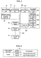
- Figure 3 is a block diagram showing configuration of a control device and controlled devices according to the first embodiment.
- device control system 100 includes controlled devices and a control device controlling these controlled devices.
- network 300 inside home 200 has controlled devices connected thereto including first camera 400, second camera 500, intercom 600, air conditioner 700, lighting device 800, and display device 900 such as a TV receiver (described as TV, hereinafter) having the function as a control device.
- TV TV
- control device and controlled devices communicate via TCP/IP (Transmission Control Protocol/Internet Protocol).
- TCP/IP Transmission Control Protocol/Internet Protocol
- the control device and controlled devices acquire an IP address first, and then multicast a command for detecting connected devices to inform each device on network 300 that they have been connected. More specifically, the control device and controlled devices inform all the devices connected to network 300 by multicasting that new devices have been connected and of their function details. After that, the control device and controlled devices inform network 300 of their own presence at regular time intervals. In this way, the control device receives a message from a controlled device and stores the message, and thus can control the controlled device according to the list stored.
- the control device can determine connection conditions of devices connected to network 300 at regular time intervals to update the list to the latest circumstances.
- control device exchanges with the controlled device messages describing (on XML base) device information and service information (e.g. which product category each device belongs to, what function each device provides).
- Hypertext HTTP protocol
- operation-related information on the controlled device is passed to the control device through the extended area of UPnP specifications.
- operation-related information 30 on the controlled device is described in the extended area of DDD (Device Description Document), for example, which is device information of UPnP.
- DDD Device Description Document
- product category information e.g. camera
- operation information representing an operation function e.g. monitor, operate
- URL information representing the destination from which an operation screen for the operation function is acquired.
- messages are exchanged between the control device and controlled devices according to preliminarily determined specifications.
- the control device can thus perform operation setting specific to the controlled device and can use functions specific to the controlled device by using operation-related information 30 of the controlled device.
- First camera 400 and second camera 500 can take an image of a subject.
- First camera 400 and second camera 500 can output an image taken by camera function to display device 900 through network 300.
- Intercom 600 placed such as at an entrance, allows talking with a visitor.
- Intercom 600 further includes a camera and takes an image of a visitor with this camera.
- Intercom 600 thus has conversation function and camera function.
- Intercom 600 can output an image and sound obtained by using the conversation and camera functions to display device 900 through network 300.
- Air conditioner 700 can condition temperature and humidity in a room by setting function.
- air conditioner 700 has functions such as Cool, Heat, Dry, and Fan and is operated such as with a dedicated remote controller (described as "remote control” hereinafter).
- Air conditioner 700 is also operated from display device 900 through network 300.
- Lighting device 800 can adjust brightness of a room by using brightness adjusting function.
- device control system 100 can control first camera 400, second camera 500, intercom 600, air conditioner 700, and lighting device 800 from display device 900 through network 300.
- display device 900 acquires operation-related information such as device ID information, product category information, operation information, and URL information from each controlled device. Then, display device 900, after specifying operation information (function) contained in the operation-related information, acquires an operation screen provided at the corresponding URL destination, thereby allowing a corresponding controlled device to be operated based on the operation screen.
- operation-related information such as device ID information, product category information, operation information, and URL information
- display device 900 after specifying operation information (function) contained in the operation-related information, acquires an operation screen provided at the corresponding URL destination, thereby allowing a corresponding controlled device to be operated based on the operation screen.
- a unified control command for controlling a controlled device such as definition information compliant with ECHONET (Energy Conservation and HOmecare NETwork), for example, can be used.
- ECHONET Electronic Engineering and HOmecare NETwork
- a controlled device can be controlled without requiring preliminarily to know information on the controlled device.
- any controlled device can be handled as long as it is compliant with known interconnect specifications (not limited to ECHONET) allowing unified controlling.
- Interconnect specifications may be HAVi (Home Audio/Video Interoperability), HBS (Home Bus System), or IEEE 1394 Serial Bus, for example.
- categories include sensor-related device, housing-equipment-related device, health-related device, and management-and-operation-related device.
- controlled devices belonging to each category are defined.
- air-conditioning-related device for example, devices are defined as a class such as home air conditioner, cold air fan, electric fan, ventilation fan, and air cleaner.
- a controlled device compliant with ECHONET specifications is obliged to contain an identification code for the above-described category and class, so that a category code and class code can be read directly from each controlled device through network 300.
- a class has an attribute identifier called an EPC (ECHONET property code), where an identification code representing the property of each controlled device is allocated to the attribute identifier.
- EPC ECHONET property code
- Each EPC has a property value called EDT (ECHONET property value data) defined, where typically each unique EDT is defined for each EPC.
- the class of home air conditioner for example, has the EPC of operation mode, to which the EDTs of Cool, Heat, Dry, Fan, and Auto are defined.
- a control device acquires identifying information and operation-related information on each controlled device, and acquires definition information for controlling each controlled device in a unified manner to exercise control.
- display device 900 as a control device includes communication unit 921, information acquiring unit 922, information classifying unit 923, menu generating unit 924, display unit 925, and page operation unit 926 as shown in Figure 3 .
- Communication unit 921 communicates with controlled devices X1 through Xn connected to network 300.
- Controlled device X1 through Xn is one of first camera 400, second camera 500, intercom 600, air conditioner 700, or lighting device 800 in Figure 1 , for example.
- Information acquiring unit 922 acquires operation-related information from controlled devices X1 through Xn through communication unit 921. Here, controlled devices X1 through Xn connected to network 300 can be changed.
- information acquiring unit 922 determines connection conditions of controlled devices X1 through Xn connected to network 300 at given time intervals. Then, information acquiring unit 922 acquires the latest operation-related information including identifying information, operation information, and URL information corresponding to the operation information for each of controlled devices X1 through Xn connected to network 300, and updates operation-related information already acquired.
- Information classifying unit 923 classifies URL information into plural function groups based on operation information contained in operation-related information on each controlled devices X1 through Xn, acquired by information acquiring unit 922. Here, when operation-related information is updated, information classifying unit 923 reclassifies operation-related information into plural function groups based on the operation-related information updated.
- Menu generating unit 924 dynamically generates a menu page for each function group classified by information classifying unit 923.
- menu generating unit 924 dynamically generates a menu page according to the function group reclassified. Further details about generation of a menu page by menu generating unit 924 are described later.
- Display unit 925 displays a menu page generated by menu generating unit 924.
- Page operation unit 926 operates the menu page displayed on display unit 925 and a URL screen transmitted from processing unit 29.
- each of controlled devices X1 through Xn includes communication unit 27, operation-related information storing unit 28, and page processing unit 29.
- Communication unit 27 communicates with display device 900 connected to network 300.
- Operation-related information storing unit 28 stores such as device identifying information and operation-related information. More specifically, operation-related information storing unit 28 stores such as device ID information, product category information, operation information, and definition information (e.g. URL information). Figure 4 shows an example of information stored.
- page processing unit 29 When page processing unit 29 receives a display request for an operation screen page based on URL information from display device 900, page processing unit 29 delivers an operation screen page (e.g. a page described in HTML (Hyper Text Markup Language)) specified by the URL information through communication unit 27.
- an operation screen page e.g. a page described in HTML (Hyper Text Markup Language)
- controlled device X1 through Xn receives an operation instruction from display device 900
- controlled device X1 through Xn executes its corresponding operation instruction.
- Each of controlled devices X1 through Xn has its unique function and operation-related information corresponding to the unique function.
- each of controlled devices X1 through Xn stores product category information, operation information, and operation-related information 30 containing URL information related to the operation information, as shown in Figure 4 .
- controlled device X1 through Xn when controlled device X1 through Xn receives a request for operation-related information 30 from display device 900, controlled device X1 through Xn responds to display device 900 such as with device ID information and definition information (e.g. product category information) in addition to operation information and URL information related to the operation information, as operation-related information 30. In this responding, the extended area of UPnP specifications is used.
- device ID information and definition information e.g. product category information
- FIG. 5 is a transition diagram showing an example of menu generation in display device 900 according to the first embodiment.
- information classifying unit 923 extracts viewing function ( monitor ) and operation setting function ( operate ) from operation information contained in operation-related information 30.
- a description is made of a case where the URL information is classified into the viewing function group (related to viewing function) and the operation setting function group (related to operation setting function).
- menu generating unit 924 first generates basic menu page 40 for allowing a user to select a function group.
- the user views this basic menu page 40 to monitor only a device for a target function.
- basic menu page 40 such as set menu 41 allowing a user to select operation setting function; and view menu 42 allowing a user to select viewing function are created according to the above-described function groups grouped by information classifying unit 923.
- the view menu 42 is an example of the above-described viewing function group related to viewing function;
- the set menu 41 is an example of the above-described operation setting function group related to operation setting function.
- menu generating unit 924 creates a list menu of devices having operation setting function out of controlled devices X1 through Xn connected to network 300, as set menu page 43 when set menu 41 is selected by the user. Similarly, menu generating unit 924 creates a list menu of devices having viewing function out of controlled devices X1 through Xn connected to network 300, as view menu page 44 when view menu 42 is selected by the user.
- Intercom 600 has both viewing function (e.g. an image taken by the camera, sound in a conversation function) and operation setting function (e.g. adjusting the camera sensitivity, volume setting). Therefore information classifying unit 923 classifies intercom 600 into the viewing function group related to viewing function and the operation setting function group related to operation setting function. Menu generating unit 924 thus creates a menu from which intercom 600 can be selected both in set menu page 43 and view menu page 44.
- viewing function e.g. an image taken by the camera, sound in a conversation function
- operation setting function e.g. adjusting the camera sensitivity, volume setting
- menu generating unit 924 generates an operation screen page for being displayed on a part of display unit 925, according to a function of controlled device X1 through Xn selected in set menu page 43 and view menu page 44.
- URL information correlated with air conditioner item is transmitted to communication unit 27 of air conditioner 700 through communication unit 921.
- operation screen page 45 related to operation setting function is acquired from page processing unit 29 of air conditioner 700, and operation screen page 45 related to operation setting function is displayed on a part of display unit 925.
- Operation screen page 45 includes temperature menu 46a, fan speed menu 46b, up menu 47a, and down menu 47b to allow operation setting function to be operated.
- the user can operate up menu 47a and down menu 47b in conjunction with temperature menu 46a. Similarly, the user can operate up menu 47a and down menu 47b in conjunction with fan speed menu 46b. In this way, the user can operate setting of the temperature and setting of the fan speed of air conditioner 700 from page operation unit 926.
- operation screen page 48 related to viewing function acquired from page processing unit 29 of second camera 500 is displayed on a part of display unit 925.
- Operation screen page 48 is provided with image display area 49 where an image from second camera 500 appears, allowing an image from second camera 500 to be displayed within the image display area.
- information classifying unit 923 classifies URL information into the viewing function group related to viewing function; and the operation setting function group related to operation setting function, based on operation information contained in operation-related information 30.
- menu generating unit 924 can dynamically generate set menu page 43 and view menu page 44, based on operation information for each function group.
- set menu page 43 and view menu page 44 are displayed on display unit 925, allowing the user to operate the device from page operation unit 926.
- the user thus can directly operate a target function. More specifically, when the user desires to view an image taken by second camera 500 (i.e. controlled device), the user operates the operation screen of view menu page 44 in the function group related to viewing function to view the image.
- the apparatus thus places a light burden in operation on the user and reduces operation time, allowing the user to operate a controlled device easily and intuitively.
- Figure 6 illustrates a control sequence in device control system 100 according to the first embodiment.
- display device 900 when display device 900 detects that a new controlled device has been connected to network 300 (S1100), display device 900 requests operation-related information from the controlled device (S1102). At this moment, the controlled device reads operation-related information from operation-related information storing unit 28 (S1104) and responds to display device 900 with operation-related information (S1106).
- S1100 through S1106 are executed each time a new controlled device is connected to network 300. More specifically, display device 900 determines connection conditions of controlled devices X1 through Xn in network 300 at given time intervals to acquire the latest operation-related information on controlled devices X1 through Xn connected network 300. When controlled device X1 through Xn connected to network 300 has been changed, display device 900 updates operation-related information acquired from each of controlled devices X1 through Xn according to the connection conditions.
- display device 900 groups operation information contained in the operation-related information by function (S1108). For example, display device 900 extracts viewing function ( monitor ) and operation setting function ( operate ) from operation-related information 30 in Figure 2 , and classifies them into the viewing function group related to viewing function; and the operation setting function group related to operation setting function. This classification process is performed such as every time operation-related information on controlled devices X1 through Xn is newly acquired, and when the power to display device 900 is turned on.
- display device 900 reclassifies the operation information into plural function groups based on operation-related information acquired.
- menu generating unit 924 of display device 900 dynamically generates a menu page by function group (S1110).
- display device 900 creates set menu 41 allowing a user to select operation setting function; and view menu 42 allowing a user to select viewing function, as basic menu page 40.
- menu generating unit 924 dynamically generates a menu page according to the reclassification of function groups. In this way, the user can monitor the latest connection conditions to identify only a device with a target function on the menu page.
- menu generating unit 924 creates a list menu of devices having operation setting function out of controlled devices X1 through Xn connected to network 300, as set menu page 43 when set menu 41 has been selected by the user. Meanwhile, menu generating unit 924 creates a list menu of devices having viewing function out of controlled devices X1 through Xn connected to network 300, as view menu page 44 when view menu 42 has been selected by the user.
- Menu generating unit 924 further generates operation screen pages 45 and 48 for displaying on a part of display unit 925, according to a function of controlled device X1 through Xn selected in set menu page 43 and view menu page 44. If display device 900 is a TV, the user operates controlled device X1 through Xn while viewing a program, and thus the display preferably appears on a part of display unit 925.
- display device 900 displays either one of basic menu page 40, set menu page 43, view menu page 44, and operation screen pages 45 and 48, on a part of display unit 925 according to operation by the user (S1112).
- the user enters operation instructions on the operation screen page for controlled device X1 through Xn according to a menu page displayed on display unit 925 from page operation unit 926 (S1114).
- display device 900 transmits the operation instruction to controlled device X1 through Xn (S1116).
- Controlled device X1 through Xn executes a function set according to the operation instruction (S1118).
- display device 900 divides operation information into the viewing function group related to viewing function; and operation setting function group related to operation setting function, based on operation information of operation-related information 30. Then, display device 900 can dynamically generate set menu page 43 and view menu page 44 based on operation information for each function group, according to connection conditions of controlled device X1 through Xn connected to network 300. Display device 900 further displays set menu page 43 and view menu page 44 on display unit 925 and allows them to be operated from page operation unit 926. The user thus can select a function group to directly operate a target function. For example, when the user desires to view an image taken by second camera 500 (i.e.
- the user operates view menu page 44 in the function group related to viewing function to allow an image taken by second camera 500 to be displayed directly on display unit 925.
- the apparatus thus places a light burden in operation on the user and reduces operation time, allowing the user to operate a controlled device easily.
- display device 900 can be provided allowing plural controlled devices X1 through Xn connected to network 300 to be operated easily.
- FIG. 1 shows configuration of operation-corresponding information for a controlled device according to the second embodiment.
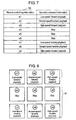
- Figure 8 is a relationship diagram showing correspondence between a menu arrangement and an operation command in display device 900 according to the second embodiment.
- operation-corresponding information 50 is transmitted that is produced by correlating key information of the remote control used for display device 900 with operation command information for each of controlled devices X1 through Xn, together with operation-related information, from controlled devices X1 through Xn.
- display device 900 acquires operation-corresponding information 50 describing relationship of correspondence between a remote control key number used by controlled device X1 through Xn and operation command information, from controlled device X1 through Xn.
- operation-corresponding information 50 of Figure 7 the first menu of the remote control key information is indicated as #1 in Figure 7 ; the second menu, as #2; and the rest in the same way.
- display device 900 stores operation-corresponding information 50 in the storing unit (not shown).
- Display device 900 correlates a key number of the remote control used for display device 900 with a menu number in menu page 51, based on operation-corresponding information 50 stored.
- Display device 900 makes display unit 925 display a remote control screen corresponding to respective controlled devices X1 through Xn, based on a request from the user. Then, display device 900 controls respective controlled devices X1 through Xn by the user operating the remote control.
- the first menu in menu page 51 is made correlate with low-speed forward playback (operation command), and this first menu is operated from the remote control to allow low-speed forward playback to be executed.
- the first menu is indicated as #1; the second menu, #2; and the rest in the same way.
- display device 900 correlates the normal-speed forward playback with the second menu; high-speed forward playback to the third; stop to the fourth through sixth; low-speed reverse playback to the seventh; normal-speed reverse playback to the eighth; and high-speed reverse playback to the ninth.
- the user can operate respective remote control key numbers to control functions of a controlled device.
- screen information acquired from an external server or a controlled device may be used other than by being generated by menu generating unit 924.
- a menu screen described in HTML, or a menu screen provided in GIF, JPEG, or bitmapped image format may be acquired from an external server to be used.
- display device 900 correlates a menu number present in menu page 51 newly generated with a key number of the remote control used for display device 900. Accordingly, controlled devices X1 through Xn can be operated without requiring to know the code of the remote control key for controlled devices X1 through Xn. That is to say, display device 900 does not need to preliminarily store operation-corresponding information on all the controlled devices, thereby reducing the storage capacity. Further, devices inside device control system 100 can be increased flexibly. Also, the user can use a familiar remote control for display device 900, improving the convenience.
- Menu generating unit 924 may dynamically generate a menu page based on given priority provided in operation information. For example, since display device 900 includes display unit 925, menu generating unit 924 generates a menu page so that a menu page for viewing function can be operated first, and during the generation process, menu generating unit 924 generates a menu page for operation setting function. A menu page thus can be dynamically generated according to the function of the control device, facilitating operation by the user to improve the operation efficiency.
- display device 900 can be equipped with operation history information storing unit 9261 storing URL selection information in the menu page operated from page operation unit 926 as operation history information.
- Menu generating unit 924 may give higher priority to URL information more frequently selected, based on this operation history information to dynamically generate a menu page where URL information appears in descending order of priority. Such arrangement allows a menu item (URL destination) frequently used by the user to be generated preferentially and to be displayed, thereby improving the operation efficiency and facilitating the operation.
- menu generating unit 924 controls the menu size, character size, and the number of menu lists according to the given display size.
- layout control unit 9251 may be provided that dynamically changes the display aspect of a menu page generated by menu generating unit 924. Such arrangement allows a user-friendly menu page to be dynamically generated, thereby improving the user's operation efficiency and facilitating the operation.
- layout control unit 9251 may delete a menu item that is old or infrequently used according to the number of items displayed, based on the number of selection times and selection date and time stored in the operation history information storing unit.
- Layout control unit 9251 may change the display aspect of menu items according to the number of menu items displayed instead of deleting menu items. For example, others item may be newly generated to include a menu item infrequently selected in others item. Further, the display size of a menu page and the character size of a menu item may be changed according to the screen size of the display device. In this way, a menu page frequently operated by the user or highly likely to be operated can be dynamically generated, thereby providing a user-friendly menu page, improving the user's operation efficiency and facilitating the operation.
- display device 900 is a TV.
- equipment having display function may be equipped with a display device including communication unit 921, information acquiring unit 922, information classifying unit 923, menu generating unit 924, and page operation unit 926.
- the display device is applicable such as to a mobile phone, remote control with display function, home information panel, and personal computer.
- menu display can be performed that improves the user's operation efficiency and facilitates the operation.
- the information classifying unit can create plural function groups based on operation information of operation-related information, and the menu generating unit can generate a menu page for each of plural function groups classified. Then, the display unit displays the menu page while the user operates from the page operation unit.
- the user thus can operate a controlled device from a target function group. For example, when the user desires to view a camera image with a controlled device, the user can operate only a controlled device having viewing function by operating a menu page in the function group related to viewing function.
- the display device thus places a light burden in operation on the user and reduces operation time, allowing the user to operate a controlled device easily.
- operation information is classified into the viewing function group related to viewing function and into the operation setting function group related to operation setting function.
- the menu generating unit can generate separate menu pages for the viewing function group related to viewing function and for the operation setting function group related to operation setting function, respectively. Accordingly, the user can operate a controlled device for a target function from a menu page simply by selecting the viewing function group and the operation setting function group, thereby reducing the operation time.
- information acquired from a controlled device is effectively used, thereby improving the user's operation efficiency.
- URL information based on given priority can be stored and displayed preferentially.
- the display device equipped with a display unit, can store URL information related to viewing function preferentially if the URL destination has two functions described therein, thereby allowing the display device to generate a menu page in the order of closeness to functions possessed by the display device. This improves the operation efficiency when the user operates.
- the display size of a menu page and the character size of a menu item can be changed according to the screen size of the display device, thereby providing a user-friendly menu page.
- a remote controller screen based on operation-corresponding information can be operated, and a controlled device can be operated by operating the remote controller screen without requiring to know key information for the controlled device.
- the present invention provides a display device allowing plural controlled devices connected to a network to be easily operated.
- a menu page can be dynamically generated and operated that has been grouped based on functions described in operation-related information on each controlled device connected to a network.
- the present invention places a light burden in operation on the user and reduces operation time, allowing the user to operate a controlled device easily, and thus is useful such as for a display device and device control system.
Landscapes
- Engineering & Computer Science (AREA)
- Automation & Control Theory (AREA)
- Signal Processing (AREA)
- Computer Networks & Wireless Communication (AREA)
- General Physics & Mathematics (AREA)
- Physics & Mathematics (AREA)
- Computer Security & Cryptography (AREA)
- Theoretical Computer Science (AREA)
- Human Computer Interaction (AREA)
- Computer Hardware Design (AREA)
- Software Systems (AREA)
- General Engineering & Computer Science (AREA)
- Selective Calling Equipment (AREA)
Claims (6)
- Dispositif d'affichage connecté via un réseau à une pluralité de dispositifs commandés (400, 500, 600, 700, 800, 900, X1, X2, X3, Xn), comprenant :une unité d'acquisition d'information (922) qui acquiert de l'information relative au fonctionnement (30), contenant de l'information de fonctionnement qui désigne des fonctions de chacun des dispositifs et de l'information d'URL correspondant à l'information de fonctionnement, provenant des dispositifs commandés ;une unité de classification d'information (923) qui classifie l'information d'URL dans une pluralité de groupes fonctionnels (41, 42) correspond chacun à une fonction sur base de l'information de fonctionnement ;une unité de génération de menu (924) qui génère une page de menu (43, 44) indiquant les dispositifs commandés qui sont autorisés à mettre en oeuvre la fonction pour chacun des groupes fonctionnels (41, 42) ;une unité d'affichage (925) qui affiche la page de menu (43, 44) ; etune unité de fonctionnement de page (926) qui accède de l'information d'URL correspondante en sélectionnant le dispositif commandé indiqué dans la page de menu (43, 44).
- Dispositif d'affichage selon la revendication 1, dans lequel les groupes fonctionnels (41, 42) comprennent :un groupe de fonction de visualisation (42) relatif à la fonction de visualisation ; etun groupe de fonction de paramètre de fonctionnement (41) relatif à une fonction de paramètre de fonctionnement.
- Dispositif d'affichage selon la revendication 1 ou 2,
dans lequel l'information de fonctionnement est prioritaire, et
dans lequel l'unité de génération de menu (924) génère la page de menu (43, 44) sur base de la priorité. - Dispositif d'affichage selon la revendication 3, comprenant en outre :une unité de stockage d'information d'historique de fonctionnement (9261) qui stocke de l'information d'URL à laquelle a accédé l'unité de fonctionnement de page (926) comme de l'information d'historique de fonctionnement,dans lequel l'unité de génération de menu (924) génère la page de menu (43, 44) sur base de l'information d'historique de fonctionnement stockée dans l'unité de stockage d'information d'historique de fonctionnement (9261) en fonction de la priorité.
- Dispositif d'affichage selon la revendication 4, comprenant en outre :une unité de contrôle d'agencement (9251) qui change un ratio d'affichage d'un élément de menu sur la page de menu (43, 44) en fonction de l'information d'historique de fonctionnement.
- Dispositif d'affichage selon l'une quelconque des revendications 1 à 5,
dans lequel l'unité d'acquisition d'information (922) acquiert en outre de l'information correspondant au fonctionnement créée par corrélation d'information
clé pour un contrôleur distant du dispositif commandé avec de l'information de commande de fonctionnement, et
dans lequel l'unité d'affichage (925) affiche un écran de contrôleur distant généré par l'unité de génération de menu (924) sur base de l'information correspondant au fonctionnement, et le dispositif commandé est commandé en utilisant de l'information de commande de fonctionnement correspondant à une clé sur l'écran de contrôleur distant.
Applications Claiming Priority (2)
| Application Number | Priority Date | Filing Date | Title |
|---|---|---|---|
| JP2008020466A JP5119953B2 (ja) | 2008-01-31 | 2008-01-31 | 表示装置 |
| PCT/JP2009/000342 WO2009096183A1 (fr) | 2008-01-31 | 2009-01-29 | Dispositif d'affichage |
Publications (3)
| Publication Number | Publication Date |
|---|---|
| EP2117255A1 EP2117255A1 (fr) | 2009-11-11 |
| EP2117255A4 EP2117255A4 (fr) | 2013-11-06 |
| EP2117255B1 true EP2117255B1 (fr) | 2015-01-21 |
Family
ID=40912538
Family Applications (1)
| Application Number | Title | Priority Date | Filing Date |
|---|---|---|---|
| EP09705840.8A Not-in-force EP2117255B1 (fr) | 2008-01-31 | 2009-01-29 | Dispositif d'affichage |
Country Status (4)
| Country | Link |
|---|---|
| US (1) | US8745532B2 (fr) |
| EP (1) | EP2117255B1 (fr) |
| JP (1) | JP5119953B2 (fr) |
| WO (1) | WO2009096183A1 (fr) |
Families Citing this family (9)
| Publication number | Priority date | Publication date | Assignee | Title |
|---|---|---|---|---|
| JP2011066850A (ja) * | 2009-09-18 | 2011-03-31 | Fujitsu Toshiba Mobile Communications Ltd | 情報通信端末 |
| WO2011061920A1 (fr) * | 2009-11-18 | 2011-05-26 | パナソニック株式会社 | Système de télécommande radio, et procédé d'appariement de télécommandes radio |
| WO2012008628A1 (fr) * | 2010-07-13 | 2012-01-19 | 엘지전자 주식회사 | Terminal mobile et procédé de configuration pour écran de veille associé |
| KR101718894B1 (ko) | 2011-11-29 | 2017-03-23 | 삼성전자주식회사 | 기기 제어를 위한 유저 인터페이스 제공 시스템 및 방법 |
| JP6192907B2 (ja) * | 2012-08-06 | 2017-09-06 | 京セラ株式会社 | エネルギー管理装置、エネルギー管理システムおよびエネルギー管理方法 |
| CN104169658B (zh) | 2013-02-20 | 2017-09-19 | 松下电器(美国)知识产权公司 | 便携信息终端的控制方法和程序 |
| JP6688954B2 (ja) * | 2015-11-18 | 2020-04-28 | パナソニックIpマネジメント株式会社 | メッセージ受信装置及び画面遷移方法 |
| KR102339857B1 (ko) * | 2017-03-29 | 2021-12-16 | 삼성전자주식회사 | 외부의 IoT 장치를 관리 및 제어하는 방법 및 이를 지원하는 전자 장치 |
| CN109783707A (zh) * | 2019-01-23 | 2019-05-21 | 欧普照明股份有限公司 | 一种监控系统的模式设置方法和装置 |
Family Cites Families (25)
| Publication number | Priority date | Publication date | Assignee | Title |
|---|---|---|---|---|
| JP3302425B2 (ja) * | 1993-01-29 | 2002-07-15 | パイオニア株式会社 | 選択方法及び選択装置 |
| US5396264A (en) * | 1994-01-03 | 1995-03-07 | Motorola, Inc. | Automatic menu item sequencing method |
| DE69838439T2 (de) * | 1997-06-25 | 2008-06-12 | Samsung Electronics Co., Ltd., Suwon | Verfahren und Vorrichtung zur Überwachung von Geräten in einem Hausnetzwerk |
| US6580950B1 (en) * | 2000-04-28 | 2003-06-17 | Echelon Corporation | Internet based home communications system |
| JP2001344163A (ja) * | 2000-05-31 | 2001-12-14 | Matsushita Electric Ind Co Ltd | 信号処理装置、媒体および情報集合体 |
| US7184024B2 (en) * | 2000-06-30 | 2007-02-27 | Nokia Corporation | Method and apparatus for mapping an input location with a displayed functional representation |
| EP1233602A4 (fr) * | 2000-09-27 | 2004-09-08 | Ntt Docomo Inc | Procede de commande a distance de dispositifs electroniques et installation de gestion de ces dispositifs |
| JP4434467B2 (ja) | 2000-11-01 | 2010-03-17 | キヤノン株式会社 | ユーザインタフェース制御装置 |
| US8190695B2 (en) * | 2001-08-02 | 2012-05-29 | Sony Corporation | Remote control system and remote control method, device for performing remote control operation and control method therefor, device operable by remote control operation and control method therefor, and storage medium |
| JP2003309884A (ja) * | 2002-04-18 | 2003-10-31 | Matsushita Electric Ind Co Ltd | リモートコントロール装置および記録媒体 |
| AU2003242047A1 (en) * | 2002-06-19 | 2004-01-06 | Matsushita Electric Industrial Co., Ltd. | Server, electronic apparatus, external apparatus and information processing system using them, and electronic apparatus setting and status acquisition method |
| KR100932813B1 (ko) * | 2002-10-01 | 2009-12-21 | 엘지전자 주식회사 | 동일 유형의 홈 네트웍 기기를 위치별로 구분 및 표시하는장치 |
| AU2003246151A1 (en) * | 2003-05-30 | 2005-01-21 | Lg Electronics, Inc. | Home network system |
| KR100606760B1 (ko) * | 2003-07-07 | 2006-07-31 | 엘지전자 주식회사 | 사용자 예약에 따른 홈 네트워크 시스템 및 그 제어방법 |
| JP4073455B2 (ja) * | 2004-01-19 | 2008-04-09 | 松下電器産業株式会社 | 顧客管理方法及びそのプログラム |
| US7786891B2 (en) * | 2004-08-27 | 2010-08-31 | Embarq Holdings Company, Llc | System and method for an interactive security system for a home |
| JP4041118B2 (ja) * | 2004-11-24 | 2008-01-30 | 株式会社東芝 | ゲートウェイ装置、ネットワークシステム、通信プログラム及び通信方法 |
| CN101218790A (zh) * | 2005-07-04 | 2008-07-09 | Sk电信股份有限公司 | 家庭网络系统及其控制方法、设置家庭网络系统的住宅网关的方法以及处理家庭网络系统的事件协议的方法 |
| KR20070062094A (ko) * | 2005-12-12 | 2007-06-15 | 삼성전자주식회사 | Ui제공 장치 및 방법 |
| US7877467B2 (en) * | 2005-12-28 | 2011-01-25 | Panasonic Electric Works Co., Ltd | Network equipment system |
| US20070276691A1 (en) * | 2006-05-12 | 2007-11-29 | Ordercatcher, Llc | System and method for processing orders from a menu |
| KR100822706B1 (ko) * | 2006-12-08 | 2008-04-17 | 한국전자통신연구원 | 근거리 무선 통신을 이용한 가전기기 제어 장치 및 그 방법 |
| US8170183B2 (en) * | 2007-01-22 | 2012-05-01 | Control4 Corporation | Systems and methods for providing a message service for a site |
| US8310335B2 (en) * | 2007-09-07 | 2012-11-13 | Verizon Patent And Licensing Inc. | Network-based access and control of home automation systems |
| US7639907B2 (en) * | 2007-11-14 | 2009-12-29 | Elbex Video Ltd. | Method and apparatus for operating AC powered appliances via video interphones, two way IR drivers and remote control devices |
-
2008
- 2008-01-31 JP JP2008020466A patent/JP5119953B2/ja not_active Expired - Fee Related
-
2009
- 2009-01-29 EP EP09705840.8A patent/EP2117255B1/fr not_active Not-in-force
- 2009-01-29 US US12/597,000 patent/US8745532B2/en not_active Expired - Fee Related
- 2009-01-29 WO PCT/JP2009/000342 patent/WO2009096183A1/fr not_active Ceased
Also Published As
| Publication number | Publication date |
|---|---|
| EP2117255A1 (fr) | 2009-11-11 |
| EP2117255A4 (fr) | 2013-11-06 |
| JP2009182771A (ja) | 2009-08-13 |
| US8745532B2 (en) | 2014-06-03 |
| WO2009096183A1 (fr) | 2009-08-06 |
| JP5119953B2 (ja) | 2013-01-16 |
| US20100131897A1 (en) | 2010-05-27 |
Similar Documents
| Publication | Publication Date | Title |
|---|---|---|
| EP2117255B1 (fr) | Dispositif d'affichage | |
| KR101844021B1 (ko) | 메시지 전송 방법 및 장치와 컴퓨터로 읽을 수 있는 저장 매체 | |
| KR100932813B1 (ko) | 동일 유형의 홈 네트웍 기기를 위치별로 구분 및 표시하는장치 | |
| CN1282340C (zh) | 家庭网络环境中利用图形用户接口的遥控服务处理设备 | |
| US11711277B2 (en) | Information management method | |
| US20160062330A1 (en) | Control apparatus, control method, program and system | |
| US7076550B1 (en) | Network connection apparatus and network system using this | |
| US11592961B2 (en) | Selecting a picture of a device to identify an associated codeset | |
| EP2758838A2 (fr) | Utilisation de cec d'hdmi pour identifier un jeu de codes | |
| US20080091776A1 (en) | Information processing apparatus and information processing system | |
| CN105629908A (zh) | 物联网设备控制方法和装置 | |
| KR100453968B1 (ko) | 홈 네트워크 시스템의 사용자 인터페이스 제공 방법 | |
| CN108803371A (zh) | 一种电器设备的控制方法以及装置 | |
| JP2003047075A (ja) | 機器制御システム、機器制御サーバ及び機器制御方法 | |
| KR100765482B1 (ko) | 디.엘.엔.에이 네트워크를 이용한 스케줄 정보 관리 방법및 그 장치 | |
| US8116754B2 (en) | Method of providing service menu and service in network environment and service providing apparatus thereof | |
| JP2000049831A (ja) | 家電用ネットワーク装置 | |
| KR20080061631A (ko) | 지능형 홈 네트워크 시스템 | |
| US7227461B2 (en) | Security confirmation system and method thereof | |
| Matsuda et al. | Dynamic Display Method in User Interface Based on Routing Information on Ad-hoc Wireless Communication | |
| KR20060076679A (ko) | 무선통신단말기를 이용한 홈 네트워크 제어 방법 | |
| JP2000267972A (ja) | ネットワークシステム、このシステムで用いられるサーバ装置 | |
| CN101166131A (zh) | 基于通用即插即用网络系统及其控制方法 | |
| JP5215697B2 (ja) | 画面表示方法 | |
| JP2001274818A (ja) | ネットワーク装置 |
Legal Events
| Date | Code | Title | Description |
|---|---|---|---|
| PUAI | Public reference made under article 153(3) epc to a published international application that has entered the european phase |
Free format text: ORIGINAL CODE: 0009012 |
|
| 17P | Request for examination filed |
Effective date: 20090928 |
|
| AK | Designated contracting states |
Kind code of ref document: A1 Designated state(s): AT BE BG CH CY CZ DE DK EE ES FI FR GB GR HR HU IE IS IT LI LT LU LV MC MK MT NL NO PL PT RO SE SI SK TR |
|
| DAX | Request for extension of the european patent (deleted) | ||
| A4 | Supplementary search report drawn up and despatched |
Effective date: 20131009 |
|
| RIC1 | Information provided on ipc code assigned before grant |
Ipc: H04L 12/28 20060101ALI20131003BHEP Ipc: H04Q 9/00 20060101AFI20131003BHEP |
|
| GRAP | Despatch of communication of intention to grant a patent |
Free format text: ORIGINAL CODE: EPIDOSNIGR1 |
|
| INTG | Intention to grant announced |
Effective date: 20140813 |
|
| GRAS | Grant fee paid |
Free format text: ORIGINAL CODE: EPIDOSNIGR3 |
|
| GRAA | (expected) grant |
Free format text: ORIGINAL CODE: 0009210 |
|
| AK | Designated contracting states |
Kind code of ref document: B1 Designated state(s): AT BE BG CH CY CZ DE DK EE ES FI FR GB GR HR HU IE IS IT LI LT LU LV MC MK MT NL NO PL PT RO SE SI SK TR |
|
| REG | Reference to a national code |
Ref country code: GB Ref legal event code: FG4D |
|
| REG | Reference to a national code |
Ref country code: CH Ref legal event code: EP |
|
| REG | Reference to a national code |
Ref country code: IE Ref legal event code: FG4D |
|
| REG | Reference to a national code |
Ref country code: DE Ref legal event code: R096 Ref document number: 602009029068 Country of ref document: DE Effective date: 20150312 |
|
| REG | Reference to a national code |
Ref country code: AT Ref legal event code: REF Ref document number: 709599 Country of ref document: AT Kind code of ref document: T Effective date: 20150315 |
|
| REG | Reference to a national code |
Ref country code: NL Ref legal event code: VDEP Effective date: 20150121 |
|
| REG | Reference to a national code |
Ref country code: AT Ref legal event code: MK05 Ref document number: 709599 Country of ref document: AT Kind code of ref document: T Effective date: 20150121 |
|
| REG | Reference to a national code |
Ref country code: LT Ref legal event code: MG4D |
|
| PG25 | Lapsed in a contracting state [announced via postgrant information from national office to epo] |
Ref country code: BE Free format text: LAPSE BECAUSE OF NON-PAYMENT OF DUE FEES Effective date: 20150131 |
|
| PG25 | Lapsed in a contracting state [announced via postgrant information from national office to epo] |
Ref country code: LT Free format text: LAPSE BECAUSE OF FAILURE TO SUBMIT A TRANSLATION OF THE DESCRIPTION OR TO PAY THE FEE WITHIN THE PRESCRIBED TIME-LIMIT Effective date: 20150121 Ref country code: FI Free format text: LAPSE BECAUSE OF FAILURE TO SUBMIT A TRANSLATION OF THE DESCRIPTION OR TO PAY THE FEE WITHIN THE PRESCRIBED TIME-LIMIT Effective date: 20150121 Ref country code: ES Free format text: LAPSE BECAUSE OF FAILURE TO SUBMIT A TRANSLATION OF THE DESCRIPTION OR TO PAY THE FEE WITHIN THE PRESCRIBED TIME-LIMIT Effective date: 20150121 Ref country code: SE Free format text: LAPSE BECAUSE OF FAILURE TO SUBMIT A TRANSLATION OF THE DESCRIPTION OR TO PAY THE FEE WITHIN THE PRESCRIBED TIME-LIMIT Effective date: 20150121 Ref country code: NO Free format text: LAPSE BECAUSE OF FAILURE TO SUBMIT A TRANSLATION OF THE DESCRIPTION OR TO PAY THE FEE WITHIN THE PRESCRIBED TIME-LIMIT Effective date: 20150421 Ref country code: HR Free format text: LAPSE BECAUSE OF FAILURE TO SUBMIT A TRANSLATION OF THE DESCRIPTION OR TO PAY THE FEE WITHIN THE PRESCRIBED TIME-LIMIT Effective date: 20150121 Ref country code: BG Free format text: LAPSE BECAUSE OF FAILURE TO SUBMIT A TRANSLATION OF THE DESCRIPTION OR TO PAY THE FEE WITHIN THE PRESCRIBED TIME-LIMIT Effective date: 20150421 |
|
| REG | Reference to a national code |
Ref country code: CH Ref legal event code: PL |
|
| PG25 | Lapsed in a contracting state [announced via postgrant information from national office to epo] |
Ref country code: IS Free format text: LAPSE BECAUSE OF FAILURE TO SUBMIT A TRANSLATION OF THE DESCRIPTION OR TO PAY THE FEE WITHIN THE PRESCRIBED TIME-LIMIT Effective date: 20150521 Ref country code: GR Free format text: LAPSE BECAUSE OF FAILURE TO SUBMIT A TRANSLATION OF THE DESCRIPTION OR TO PAY THE FEE WITHIN THE PRESCRIBED TIME-LIMIT Effective date: 20150422 Ref country code: AT Free format text: LAPSE BECAUSE OF FAILURE TO SUBMIT A TRANSLATION OF THE DESCRIPTION OR TO PAY THE FEE WITHIN THE PRESCRIBED TIME-LIMIT Effective date: 20150121 Ref country code: PL Free format text: LAPSE BECAUSE OF FAILURE TO SUBMIT A TRANSLATION OF THE DESCRIPTION OR TO PAY THE FEE WITHIN THE PRESCRIBED TIME-LIMIT Effective date: 20150121 Ref country code: NL Free format text: LAPSE BECAUSE OF FAILURE TO SUBMIT A TRANSLATION OF THE DESCRIPTION OR TO PAY THE FEE WITHIN THE PRESCRIBED TIME-LIMIT Effective date: 20150121 Ref country code: LV Free format text: LAPSE BECAUSE OF FAILURE TO SUBMIT A TRANSLATION OF THE DESCRIPTION OR TO PAY THE FEE WITHIN THE PRESCRIBED TIME-LIMIT Effective date: 20150121 |
|
| REG | Reference to a national code |
Ref country code: DE Ref legal event code: R097 Ref document number: 602009029068 Country of ref document: DE |
|
| PG25 | Lapsed in a contracting state [announced via postgrant information from national office to epo] |
Ref country code: LI Free format text: LAPSE BECAUSE OF NON-PAYMENT OF DUE FEES Effective date: 20150131 Ref country code: DK Free format text: LAPSE BECAUSE OF FAILURE TO SUBMIT A TRANSLATION OF THE DESCRIPTION OR TO PAY THE FEE WITHIN THE PRESCRIBED TIME-LIMIT Effective date: 20150121 Ref country code: SK Free format text: LAPSE BECAUSE OF FAILURE TO SUBMIT A TRANSLATION OF THE DESCRIPTION OR TO PAY THE FEE WITHIN THE PRESCRIBED TIME-LIMIT Effective date: 20150121 Ref country code: CH Free format text: LAPSE BECAUSE OF NON-PAYMENT OF DUE FEES Effective date: 20150131 Ref country code: RO Free format text: LAPSE BECAUSE OF FAILURE TO SUBMIT A TRANSLATION OF THE DESCRIPTION OR TO PAY THE FEE WITHIN THE PRESCRIBED TIME-LIMIT Effective date: 20150121 Ref country code: MC Free format text: LAPSE BECAUSE OF FAILURE TO SUBMIT A TRANSLATION OF THE DESCRIPTION OR TO PAY THE FEE WITHIN THE PRESCRIBED TIME-LIMIT Effective date: 20150121 Ref country code: EE Free format text: LAPSE BECAUSE OF FAILURE TO SUBMIT A TRANSLATION OF THE DESCRIPTION OR TO PAY THE FEE WITHIN THE PRESCRIBED TIME-LIMIT Effective date: 20150121 Ref country code: CZ Free format text: LAPSE BECAUSE OF FAILURE TO SUBMIT A TRANSLATION OF THE DESCRIPTION OR TO PAY THE FEE WITHIN THE PRESCRIBED TIME-LIMIT Effective date: 20150121 |
|
| REG | Reference to a national code |
Ref country code: IE Ref legal event code: MM4A |
|
| PLBE | No opposition filed within time limit |
Free format text: ORIGINAL CODE: 0009261 |
|
| STAA | Information on the status of an ep patent application or granted ep patent |
Free format text: STATUS: NO OPPOSITION FILED WITHIN TIME LIMIT |
|
| 26N | No opposition filed |
Effective date: 20151022 |
|
| PG25 | Lapsed in a contracting state [announced via postgrant information from national office to epo] |
Ref country code: IT Free format text: LAPSE BECAUSE OF FAILURE TO SUBMIT A TRANSLATION OF THE DESCRIPTION OR TO PAY THE FEE WITHIN THE PRESCRIBED TIME-LIMIT Effective date: 20150121 |
|
| REG | Reference to a national code |
Ref country code: FR Ref legal event code: PLFP Year of fee payment: 8 |
|
| PG25 | Lapsed in a contracting state [announced via postgrant information from national office to epo] |
Ref country code: IE Free format text: LAPSE BECAUSE OF NON-PAYMENT OF DUE FEES Effective date: 20150129 |
|
| PG25 | Lapsed in a contracting state [announced via postgrant information from national office to epo] |
Ref country code: SI Free format text: LAPSE BECAUSE OF FAILURE TO SUBMIT A TRANSLATION OF THE DESCRIPTION OR TO PAY THE FEE WITHIN THE PRESCRIBED TIME-LIMIT Effective date: 20150121 |
|
| PG25 | Lapsed in a contracting state [announced via postgrant information from national office to epo] |
Ref country code: BE Free format text: LAPSE BECAUSE OF FAILURE TO SUBMIT A TRANSLATION OF THE DESCRIPTION OR TO PAY THE FEE WITHIN THE PRESCRIBED TIME-LIMIT Effective date: 20150121 |
|
| PG25 | Lapsed in a contracting state [announced via postgrant information from national office to epo] |
Ref country code: MT Free format text: LAPSE BECAUSE OF FAILURE TO SUBMIT A TRANSLATION OF THE DESCRIPTION OR TO PAY THE FEE WITHIN THE PRESCRIBED TIME-LIMIT Effective date: 20150121 |
|
| REG | Reference to a national code |
Ref country code: FR Ref legal event code: PLFP Year of fee payment: 9 |
|
| PG25 | Lapsed in a contracting state [announced via postgrant information from national office to epo] |
Ref country code: HU Free format text: LAPSE BECAUSE OF FAILURE TO SUBMIT A TRANSLATION OF THE DESCRIPTION OR TO PAY THE FEE WITHIN THE PRESCRIBED TIME-LIMIT; INVALID AB INITIO Effective date: 20090129 |
|
| PG25 | Lapsed in a contracting state [announced via postgrant information from national office to epo] |
Ref country code: CY Free format text: LAPSE BECAUSE OF FAILURE TO SUBMIT A TRANSLATION OF THE DESCRIPTION OR TO PAY THE FEE WITHIN THE PRESCRIBED TIME-LIMIT Effective date: 20150121 |
|
| PG25 | Lapsed in a contracting state [announced via postgrant information from national office to epo] |
Ref country code: PT Free format text: LAPSE BECAUSE OF FAILURE TO SUBMIT A TRANSLATION OF THE DESCRIPTION OR TO PAY THE FEE WITHIN THE PRESCRIBED TIME-LIMIT Effective date: 20150521 |
|
| PG25 | Lapsed in a contracting state [announced via postgrant information from national office to epo] |
Ref country code: TR Free format text: LAPSE BECAUSE OF FAILURE TO SUBMIT A TRANSLATION OF THE DESCRIPTION OR TO PAY THE FEE WITHIN THE PRESCRIBED TIME-LIMIT Effective date: 20150121 |
|
| PG25 | Lapsed in a contracting state [announced via postgrant information from national office to epo] |
Ref country code: LU Free format text: LAPSE BECAUSE OF NON-PAYMENT OF DUE FEES Effective date: 20150129 |
|
| REG | Reference to a national code |
Ref country code: FR Ref legal event code: PLFP Year of fee payment: 10 |
|
| PG25 | Lapsed in a contracting state [announced via postgrant information from national office to epo] |
Ref country code: MK Free format text: LAPSE BECAUSE OF FAILURE TO SUBMIT A TRANSLATION OF THE DESCRIPTION OR TO PAY THE FEE WITHIN THE PRESCRIBED TIME-LIMIT Effective date: 20150121 |
|
| PGFP | Annual fee paid to national office [announced via postgrant information from national office to epo] |
Ref country code: GB Payment date: 20200124 Year of fee payment: 12 Ref country code: DE Payment date: 20200121 Year of fee payment: 12 |
|
| PGFP | Annual fee paid to national office [announced via postgrant information from national office to epo] |
Ref country code: FR Payment date: 20200121 Year of fee payment: 12 |
|
| REG | Reference to a national code |
Ref country code: DE Ref legal event code: R119 Ref document number: 602009029068 Country of ref document: DE |
|
| GBPC | Gb: european patent ceased through non-payment of renewal fee |
Effective date: 20210129 |
|
| PG25 | Lapsed in a contracting state [announced via postgrant information from national office to epo] |
Ref country code: FR Free format text: LAPSE BECAUSE OF NON-PAYMENT OF DUE FEES Effective date: 20210131 |
|
| PG25 | Lapsed in a contracting state [announced via postgrant information from national office to epo] |
Ref country code: GB Free format text: LAPSE BECAUSE OF NON-PAYMENT OF DUE FEES Effective date: 20210129 Ref country code: DE Free format text: LAPSE BECAUSE OF NON-PAYMENT OF DUE FEES Effective date: 20210803 |