EP2117452B1 - Trochantärer griff - Google Patents
Trochantärer griff Download PDFInfo
- Publication number
- EP2117452B1 EP2117452B1 EP08725496.7A EP08725496A EP2117452B1 EP 2117452 B1 EP2117452 B1 EP 2117452B1 EP 08725496 A EP08725496 A EP 08725496A EP 2117452 B1 EP2117452 B1 EP 2117452B1
- Authority
- EP
- European Patent Office
- Prior art keywords
- cable
- bone plate
- bores
- planes
- intersect
- Prior art date
- Legal status (The legal status is an assumption and is not a legal conclusion. Google has not performed a legal analysis and makes no representation as to the accuracy of the status listed.)
- Active
Links
- 0 C1[C@]2*1CCC2 Chemical compound C1[C@]2*1CCC2 0.000 description 1
Images

Classifications
-
- A—HUMAN NECESSITIES
- A61—MEDICAL OR VETERINARY SCIENCE; HYGIENE
- A61B—DIAGNOSIS; SURGERY; IDENTIFICATION
- A61B17/00—Surgical instruments, devices or methods
- A61B17/56—Surgical instruments or methods for treatment of bones or joints; Devices specially adapted therefor
- A61B17/58—Surgical instruments or methods for treatment of bones or joints; Devices specially adapted therefor for osteosynthesis, e.g. bone plates, screws or setting implements
- A61B17/68—Internal fixation devices, including fasteners and spinal fixators, even if a part thereof projects from the skin
- A61B17/82—Internal fixation devices, including fasteners and spinal fixators, even if a part thereof projects from the skin for bone cerclage
-
- A—HUMAN NECESSITIES
- A61—MEDICAL OR VETERINARY SCIENCE; HYGIENE
- A61B—DIAGNOSIS; SURGERY; IDENTIFICATION
- A61B17/00—Surgical instruments, devices or methods
- A61B17/56—Surgical instruments or methods for treatment of bones or joints; Devices specially adapted therefor
- A61B17/58—Surgical instruments or methods for treatment of bones or joints; Devices specially adapted therefor for osteosynthesis, e.g. bone plates, screws or setting implements
- A61B17/68—Internal fixation devices, including fasteners and spinal fixators, even if a part thereof projects from the skin
- A61B17/74—Devices for the head or neck or trochanter of the femur
-
- A—HUMAN NECESSITIES
- A61—MEDICAL OR VETERINARY SCIENCE; HYGIENE
- A61B—DIAGNOSIS; SURGERY; IDENTIFICATION
- A61B17/00—Surgical instruments, devices or methods
- A61B17/56—Surgical instruments or methods for treatment of bones or joints; Devices specially adapted therefor
- A61B17/58—Surgical instruments or methods for treatment of bones or joints; Devices specially adapted therefor for osteosynthesis, e.g. bone plates, screws or setting implements
- A61B17/68—Internal fixation devices, including fasteners and spinal fixators, even if a part thereof projects from the skin
- A61B17/84—Fasteners therefor or fasteners being internal fixation devices
- A61B17/842—Flexible wires, bands or straps
Definitions
- This invention relates generally to surgical implants used in orthopedic surgery, and more specifically to an apparatus grip useful in the attachment of a greater trochanter.
- Hip replacement surgery has become commonplace.
- the greater trochanter is commonly cut away from the femur and retracted, together with the abductor musculature to which the trochanter is attached. This greatly facilitates the surgical approach to the hip joint.
- a femoral stem is then replaced by new prosthetic implant. This technique is also employed in connection with trochanteric osteotomies and intra-operative fractures of the trochanter.
- the greater trochanter is relocated and must be reattached.
- the greater trochanter must be secured in its proper position on the proximal femur and the position maintained for a time sufficient for the bone to heal. Maintaining the proper position is difficult because of the very substantial and dynamic forces applied to the trochanter and femur, both through the femur and from the attached abductor musculature, which tends to move the trochanter in relation to the femur.
- US 2006/0235401 A1 discloses a method and apparatus for repairing a femur.
- a connector is provided having a claw-like member to engage with the greater trochanter.
- a plurality of cable apertures and cable screws to receive and engage with cables that loop around the femur.
- a plurality of cable apertures and cable screws to receive and engage with cables that loop around the femur.
- the connector may be used to re-attach the greater trochanter by impacting a connector onto the greater trochanter, positioning the greater trochanter onto the femur, passing cables around the femur and through the connector, tensioning the cables to provide engagement between the greater trochanter and the femur, and attaching the connector to the femur using at least one bone screw.
- the present invention provides a bone plate as claimed in claim 1.
- proximal and distal as used herein are defined for convenience in relation to the intended anatomical orientation of the device when surgically fixed to a greater trochanter. However, in some applications the device might be reoriented without departing from the invention. Accordingly, the terms proximal and distal should be understood only as convenient labels for the purpose of description, and not as limiting the possibilities for reorientation.
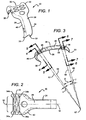
- a bone grip in accordance with the invention has a solid, substantially rigid body 20 with a relatively wider proximal portion 22 and a relatively more narrow distal neck portion 24.
- An inner face 26 of the body 20 is slightly concave in at least the proximal-distal direction, conforming to a generalized surface of a greater trochanter with its soft tissue attachments (or other bone, as required by each particular embodiment).
- An outer face 28 of the body 20 approximately follows the contour of the inner face on the opposite side of the thickness of the body.
- the overall shape of the body is thus generally shell-like, with its inner face cupped slightly inward to embrace a convex bony surface.
- the body 20 preferably has a length dimension longer than the width dimension, defining a lengthwise direction.
- the body 20 also preferably has generally bilateral symmetry so that an imaginary midplane or medial plane of symmetry is defined.
- the medial plane M of the body extends in the direction of the longer dimension (lengthwise) of the body and is disposed approximately midway across the width dimension. Because the body 20 is intended to be fixed to a femur with the long dimension extending from proximal to distal (in anatomical terms), the M plane will normally be fixed to extend in the proximal-distal direction in anatomical relation to the femur.
- the medial plane M intersects outer face 28 to define an imaginary midline.
- proximal, hooked tines 30 are separated by a gap 32.
- the tines are generally sharp, to securely engage into or over the proximal bony surface of a greater trochanter.
- the distal end has at least two smaller hooked, distal tines 33 sharpened to engage a femur (or other similar bone).
- the tines are preferably disposed symmetrically.
- the medial plane M lies midway between the proximal tines 30, midway between the distal tines 33, and generally normal to the inner and outer faces 26 and 28.
- the body 20 has at least two, and preferably a larger number of oblique bores 34a, 34b, 36a and 36b (generally identified as oblique bores).
- the bores are aligned in convergent, opposed pairs.
- bores 34a and 34b converge at an apex near the medial plane M.
- Each bore-pair comprises a cable channel, as discussed in detail below.
- at least a second set of convergent, opposed bores 36a and 36b are also provided; the second set together comprise a second cable channel.
- the oblique bores run generally transverse to the axis of the body 20, entering from a side 40 and exiting the top surface 28. It should be borne in mind that in a preferred embodiment with sides 40 and top surface nearly perpendicular, the bores will be non-perpendicular with either the top surface 28 or the sides 40. As shown in FIG. 2 , the intersection of bores 34a, 34b, 36a and 36b with the top surface 28 is acutely oblique, creating an aperture which appears elliptical (although it is not mathematically an exact ellipse). The intersection with the sides 40 is also non-perpendicular, yielding a non-circular side aperture 46 but with less eccentricity than the upper apertures where bores 34a,b and 36a,b exit the top surface 28.
- right and left bores are provided in sets, generally transverse to the medial plane M body 20 and lining up in pairs.
- Each pair of corresponding right and left bores together comprises a cable guide, having diameter complementary to a matching strand of cerclage cable.
- These cable guides are disposed to cooperate with surgical cerclage cables to allow fixation of the bone grip in the manner discussed below.
- the cross-section 4 shows that the left and right lateral bore pair 34a and 34b are generally transverse to the medial plane of the body 20, but are neither parallel nor skew to one another. Rather, the bores are angled upwards, converging toward an intersection at or above an apex approximately at the medial plane of the body 22.
- the central axes of bores 34a and 34b intersect near the top surface 28.
- the bores thus form complementary ramps sloping downward and outward from a central apex at 50.
- the axes of these ramps intersect at an obtuse angle ⁇ .
- a curved transition between ramps is preferably provided at the apex 50.
- the cable guide comprising bores 34a and 34b lies generally on and defines a first cable guide plane 52, as shown in FIG. 3 .
- Each cable guide plane is transverse to the medial plane M; but multiple ones of the cable guide planes are not necessarily parallel to one another, as discussed further below and as seen in FIG. 3 .
- the ridge separating bore 34a and 34b be slightly rounded to a saddle-like shape, to soften the transition for a cable running through 34a and 34b, passing across the apex ridge.
- This can be manufactured, for example, by threading a strong, abrasive-impregnated cable through the cable guide comprising bore pair 34a and 34b. The cable is then tensioned and pulled alternately back and forth through the channel while maintaining tension, to abrade the body and define a smooth saddle or cable groove.
- the ramps defined by 34a and 34b are preferably disposed at obtuse angles in relation to a desired direction of cable tension.
- the angle of cable tension is defined by the anatomy of the femur, and in particular the relationship between the greater and lesser trochanter. In consideration of this anatomical relationship, the arrangement of the invention tends to distribute cable stress by avoiding any acute or right-angle corners. Note that the angle ⁇ between the left face 40 of the device and the bore 34a is preferably more than 90 degrees.
- transition ⁇ between ramps again presents an obtuse angle; another obtuse angle is formed at the aperture of the right hand bore 34b in right face.
- the series of obtuse angles tends to distribute the contact stress across ramps 34a and 34b so that stress is distributed in a cable that is passed through the guides.
- FIG. 5 shows a second cable guide analogous to that of FIG. 4 .
- cut plane 5 (54 in FIG. 3 ) is not parallel with that of FIG. 4 (52 in FIG. 3 ).
- the Cut planes 54 and 52 are defined by the directions of their corresponding cable guides.
- each pair of bores (34a,b; 36a,b) are non-parallel, convergent and intersecting near an apex.
- each pair defines a plane.
- planes 52 and 54 intersect as shown at a dihedral angle a which, in a preferred embodiment, is approximately three degrees.
- the actual angle in a give embodiment is determined by the desired anatomical fixation point at which the cables are intended to converge.
- the angle is predetermined such that the cable guide planes converge near an anatomical fixation point (for example, the lesser trochanter) when the plate is fixed on the greater trochanter.
- angles ⁇ ', ⁇ ' in FIG. 5 may vary slightly from corresponding angles ⁇ , ⁇ in FIG.4 , depending on anatomical geometry for the particular application, but preferably both will be obtuse, as discussed above.
- At least one, and preferably at least two more directed cable guides 55 and 56 are provided.
- bore pairs similar to 34a,b and 36a,b are provided at 55 and 56 in the neck 24, each defining a different plane 58 and 60. (differing from one another and from plane 4 and plane 5).
- through bores 55 and 56 can be used, as illustrated in the figures.
- the alternative arrangement is more easily fabricated in a body having a neck narrower than the proximal body, as shown. This alternative is illustrated because the arrangement of 34a,b and 36a,b has already been shown and described.
- Cross sections 6 and 8 show bores 55 and 56, respectively. Although the bores are generally tranverse and pass through the body, each side is preferably counterbored at an oblique angle. The directions of the oblique counterbores provide in each bore a short ramp (shown at 62 and 64) which together with the bores defines cable guide planes 58 and 60. Alternatively, the counterbore may simply be chamfered or rounded to avoid concentration of stress in the cable.
- the apertures of all bores should be smoothed as by abrasion to a finish, for example 32 Ra (microinches) (0.8 ⁇ m) rms roughness, to prevent abrasion of an elastic, polymer cable.
- the planes 58 and (optional) 60 are not parallel to one another or to either 52 or 54.
- the dihedral angle ⁇ between the (innermost of the) proximal cable guide planes and the distal cable guide planes is approximately 22 degrees. More generally the angle could be in the range 10 to 50 degrees.
- This angle is, in any particular embodiment, determined by trochanter geometry more specifically, the angle is selected such that the cable guide planes converge at or near a predetermined fixation point (for example, the lesser trochanter). In this context, "near" is used to mean within 2 centimeters.
- the angle ⁇ between planes of the two distal neck cable guides is approximately three degrees, but may vary in response to the relative locations of the greater trochanter and fixation point in a given anatomical context.
- all of the planes defined by the multiple cable guides intersect at approximately the same line seen (pointing into the page) as 67, which corresponds with an estimated attachment point (suitably at or below the lesser trochanter). This arrangement directs all the tension vectors in a cerclage cable in the most anatomically and mechanically desirable directions, and avoids unnecessary kinks and opportunity for cable abrasion.
- FIG. 8 shows an example of a method of use for the trochanteric grip of the invention.
- the device 20 is disposed in contact with a greater trochanter at 70, with the concave inner face 26 disposed toward the bone, and the convex outer face 28 disposed outward and upward.
- the tines 33 and 30 are anatomically arranged so that the device naturally seats with the medial plane M running generally in the proximal-distal direction in relation to the patient's anatomy.
- Two lengths of elastic, polymer cable 72 are doubled to provide four strands 74, 76, 78 and 79. Each strand is passed through a cable guide: 74 passes through the bore pair 34a and 34b (comprising guide 34); 76 passes through guide 36, and so on.
- the cable is passed around the femur, preferably passing through or below the lesser trochanter; and the free ends are secured under tension.
- the looped end and the free ends can be secured under tension by a pair of locking, wedged cable clamps 82.
- An example of a suitable clamp is described in U.S. Patent application 11/147685 filed on 6/08/2005 (allowed, pending issue).
- Other means could be employed for securing the cable under tension. Two such cable segments (four strands) are shown and are preferred.
- the various strands of cable are not directed in parallel or in the same plane; rather, the loops tend to converge at 80 to engage the lesser trochanter.
- This arrangement is preferred by the surgeon for the security that it offers, and because it tends to direct the force vectors in the direction most preferred to maintain dynamic compression on the trochanter during post-surgical recovery period. This tends to promote proper healing and prevent post-operative displacement of the trochanter, which experiences large dynamic and static stresses from the muscle attachments (not shown, to maintain clarity of illustration).
- the cable guides of the present invention are preferably directed in convergent planes that follow the tension directed in a tensed, elastic cable looped through the trochanteric grip (at a first extreme of the loop) and secured around the femur at the lesser trochanter (at the opposite extreme of the loop).
- a hole, notch, or other feature may be provided on the body 20 of the invention for engaging a complementary instrument for manually manipulating the body during surgery.
- a threaded hole may optionally be provided in body 20 , for fitting to a complementary threaded shaft on an instrument.
- a shaft might alternatively be press fitted, or notches, projections, or recesses of various forms might be provided, depending on the specific design of the complementary handling instrument.
- holes may be drilled through the lesser trochanter and the cables threaded through; in other cases, it may be sufficiently secure to rely on the protrusion of the lesser trochanter to retain the cable loop (as shown in FIG. 8 ).
Landscapes
- Health & Medical Sciences (AREA)
- Orthopedic Medicine & Surgery (AREA)
- Surgery (AREA)
- Life Sciences & Earth Sciences (AREA)
- Heart & Thoracic Surgery (AREA)
- Nuclear Medicine, Radiotherapy & Molecular Imaging (AREA)
- Engineering & Computer Science (AREA)
- Biomedical Technology (AREA)
- Neurology (AREA)
- Medical Informatics (AREA)
- Molecular Biology (AREA)
- Animal Behavior & Ethology (AREA)
- General Health & Medical Sciences (AREA)
- Public Health (AREA)
- Veterinary Medicine (AREA)
- Surgical Instruments (AREA)
Claims (8)
- Knochenplatte zur Verwendung bei der Befestigung eines herausgeschnittenen knochigen Stücks auf einem breiteren Knochen, die sich zur Befestigung eines größeren Trochanters an einem Oberschenkel eignet, folgendes umfassend:einen Korpus (20), der ein proximales Ende und ein distales Ende aufweist, die an gegenüberliegenden Enden einer Längsabmessung angeordnet sind, wobei der besagte Korpus (20) auch eine Außenfläche (28) und eine Innenfläche (26) aufweist;wobei der besagte Korpus erste und zweite Kabelführungen (55, 56) aufweist, wobei die besagten ersten und zweiten Kabelführungen jeweils erste und zweite Paare an schrägen Rampen umfassen, und jedes Paar an schrägen Rampen in einem stumpfen Winkel zu einem Schnittpunkt zusammenlaufen, wobei die besagten ersten und zweiten Paare an schrägen Rampen erste und zweite Kabelführungsebenen (52, 54) definieren;wobei die besagten ersten und zweiten Kabelführungsebenen (52, 54) im Allgemeinen quer zur Längsabmessung des besagten Korpus angeordnet sind, dadurch gekennzeichnet, dass die besagten ersten und zweiten Kabelführungsebenen nicht parallel zueinander liegen und sich in einem Öffnungswinkel (α) schneiden.
- Knochenplatte nach Anspruch 1, wobei jedes der besagten Paare an schrägen Rampen ein Paar an Bohrungen (34a, 34b; 36a, 36b) umfasst, die im Allgemeinen quer zur Längsabmessung des besagten Korpus (20) und schräg zur besagten Außenfläche des besagten Korpus ausgerichtet ist, wobei jedes der besagten Paare an Bohrungen zusammenläuft, um sich nahe einer Mittelebene zu schneiden, die vom besagten Korpus (20) definiert wird.
- Knochenplatte nach Anspruch 1, wobei sich die besagten Kabelführungsebenen (52, 54) in einer Linie schneiden, die vorbestimmt ist, um nahe eines anatomischen Befestigungspunkts vorbeizuführen.
- Knochenplatte nach Anspruch 3, wobei die besagten Kabelführungsebenen angeordnet sind, um die Kabelspannung in zusammenlaufende Ebenen zu leiten, wobei die besagte Schnittlinie im Allgemeinen quer zur besagten Mittelebene des besagten Korpus angeordnet ist.
- Knochenplatte nach Anspruch 2, darüber hinaus zumindest eine weitere Bohrung umfassend, die imstande ist, ein Kabel (72) aufzunehmen.
- Knochenplatte nach Anspruch 5, wobei die besagte weitere Bohrung zumindest eine schräge Senkung aufweist, wobei die besagte schräge Senkung und die besagte Bohrung eine dritte Kabelführungsebene definieren, die quer zur besagten Längsabmessung und nicht parallel zu den beiden besagten ersten und zweiten Kabelführungsebenen verläuft.
- Knochenplatte nach Anspruch 6, wobei die besagte dritte Kabelführungsebene in einem Öffnungswinkel in einem Bereich von 10 bis 50 Grad angeordnet ist.
- Knochenplatte nach Anspruch 5, wobei die besagte weitere Bohrung eine gefaste Öffnung aufweist.
Applications Claiming Priority (2)
| Application Number | Priority Date | Filing Date | Title |
|---|---|---|---|
| US11/706,513 US20080234679A1 (en) | 2007-02-13 | 2007-02-13 | Trochanteric grip |
| PCT/US2008/001871 WO2008100525A2 (en) | 2007-02-13 | 2008-02-12 | Trochanteric grip |
Publications (3)
| Publication Number | Publication Date |
|---|---|
| EP2117452A2 EP2117452A2 (de) | 2009-11-18 |
| EP2117452A4 EP2117452A4 (de) | 2013-07-17 |
| EP2117452B1 true EP2117452B1 (de) | 2016-07-20 |
Family
ID=39690686
Family Applications (1)
| Application Number | Title | Priority Date | Filing Date |
|---|---|---|---|
| EP08725496.7A Active EP2117452B1 (de) | 2007-02-13 | 2008-02-12 | Trochantärer griff |
Country Status (4)
| Country | Link |
|---|---|
| US (1) | US20080234679A1 (de) |
| EP (1) | EP2117452B1 (de) |
| ES (1) | ES2586738T3 (de) |
| WO (1) | WO2008100525A2 (de) |
Cited By (2)
| Publication number | Priority date | Publication date | Assignee | Title |
|---|---|---|---|---|
| US11179181B2 (en) | 2018-06-15 | 2021-11-23 | Stryker European Operations Holdings Llc | Trochanter plates |
| US11786280B2 (en) * | 2018-05-17 | 2023-10-17 | TEIJIN NAKASHIMA MEDICAL CO., ltd | Treatment tool |
Families Citing this family (19)
| Publication number | Priority date | Publication date | Assignee | Title |
|---|---|---|---|---|
| US8034085B2 (en) | 2004-05-28 | 2011-10-11 | Depuy Spine, Inc. | Non-fusion spinal correction systems and methods |
| US8469966B2 (en) * | 2004-09-23 | 2013-06-25 | Smith & Nephew, Inc. | Systems, methods, and apparatuses for tensioning an orthopedic surgical cable |
| US8123749B2 (en) | 2005-03-24 | 2012-02-28 | Depuy Spine, Inc. | Low profile spinal tethering systems |
| US8282674B2 (en) * | 2008-07-18 | 2012-10-09 | Suspension Orthopaedic Solutions, Inc. | Clavicle fixation |
| EP2965702B1 (de) * | 2009-05-12 | 2018-11-07 | Synthes GmbH | Knochenfixierungselement mit selbsthaltendem kabelbinder |
| KR101095971B1 (ko) | 2009-05-27 | 2011-12-19 | 김선미 | 대퇴골의 소전자부 고정장치 |
| US8992528B2 (en) * | 2011-06-14 | 2015-03-31 | Amit Gupta | Intramedullary system for managing a bone fracture |
| US8551143B2 (en) | 2011-10-11 | 2013-10-08 | Brent Lane Norris | Low profile periarticular tension band plating system with soft tissue neutralization cable tunnel/channel |
| BR112014025410A2 (pt) * | 2012-04-12 | 2018-05-08 | T Geldwert Josef | implante cirúrgico para a correção de hallux valgus ou joanete de alfaiate |
| US9549768B2 (en) * | 2014-04-17 | 2017-01-24 | Biomet Manufacturing, Llc | Medical implant system for securing bone fragments |
| US20180085152A1 (en) * | 2014-10-24 | 2018-03-29 | Firoozeh Madadi | Intertrochanteric fixation device |
| JP6600010B2 (ja) | 2015-04-24 | 2019-10-30 | バイオメット マニュファクチャリング,リミティド ライアビリティ カンパニー | 鎖骨インプラント |
| WO2018165661A1 (en) | 2017-03-10 | 2018-09-13 | Brian Schumacher | Implants and related methods for bunion correction |
| CN108042194A (zh) * | 2017-12-25 | 2018-05-18 | 臧学慧 | 一种股骨小转子骨折复位固定捆绑带 |
| US10675072B2 (en) | 2018-01-02 | 2020-06-09 | Acumed Llc | Bone fixation with a plate and a coupler connected by flexible members |
| AU2020204191A1 (en) | 2019-06-24 | 2021-01-14 | Nextremity Solutions, Inc. | Fracture Fixation System and Method |
| FR3100968B1 (fr) * | 2019-09-24 | 2023-04-14 | Cousin Biotech | Dispositif de cerclage, notamment pour la consolidation d’une fracture péri-prothétique |
| US11925397B2 (en) | 2020-06-25 | 2024-03-12 | Medartis Ag | System and method for bone fixation |
| US11998252B2 (en) | 2020-11-18 | 2024-06-04 | Medartis Ag | System and method for bone fixation |
Family Cites Families (15)
| Publication number | Priority date | Publication date | Assignee | Title |
|---|---|---|---|---|
| GB2017502B (en) * | 1978-03-30 | 1982-09-15 | Dall D | Surgical implants |
| FR2614781B1 (fr) * | 1987-05-05 | 1989-08-04 | Galline Yves | Dispositif d'attachement et outils pour sa mise en place, notamment pour attacher le grand trochanter au femur |
| GB9206018D0 (en) * | 1992-03-19 | 1992-04-29 | Dall Desmond Meiring | Bone fixation system |
| US5324291A (en) * | 1992-12-21 | 1994-06-28 | Smith & Nephew Richards, Inc. | Bone section reattachment apparatus and method |
| EP0647436A1 (de) * | 1993-10-06 | 1995-04-12 | SMITH & NEPHEW RICHARDS, INC. | Vorrichtung zum Wiederbefestigen eines Knochenteils |
| US5415658A (en) * | 1993-12-14 | 1995-05-16 | Pioneer Laboratories, Inc. | Surgical cable loop connector |
| US5607430A (en) * | 1995-08-25 | 1997-03-04 | Biomet, Inc. | Bone stabilization implant having a bone plate portion with integral cable clamping means |
| US5741259A (en) * | 1996-02-22 | 1998-04-21 | Chan; Kwan-Ho | Surgical fastener device for use in bone fracture fixation |
| US5797916A (en) * | 1996-12-10 | 1998-08-25 | Johnson & Johnson Professional, Inc. | Trochanteric reattachment cerclage device |
| GB9715440D0 (en) * | 1997-07-22 | 1997-09-24 | Dall Desmond Meiring | Bone grip |
| US5941881A (en) * | 1998-01-09 | 1999-08-24 | Medidea, Llc | Bone fastening apparatus and related procedures |
| US5993452A (en) * | 1998-08-24 | 1999-11-30 | Biomet Inc. | Cerclage system |
| US7207993B1 (en) * | 2000-02-03 | 2007-04-24 | Pioneer Laboratories, Inc. | Apparatus and method for repairing the femur |
| US6338734B1 (en) * | 2000-03-14 | 2002-01-15 | Biomet, Inc. | Method and apparatus for trochanter fixation |
| US7229444B2 (en) * | 2004-08-25 | 2007-06-12 | Howmedica Osteonics Corp. | Trochanteric cerclage plate |
-
2007
- 2007-02-13 US US11/706,513 patent/US20080234679A1/en not_active Abandoned
-
2008
- 2008-02-12 EP EP08725496.7A patent/EP2117452B1/de active Active
- 2008-02-12 WO PCT/US2008/001871 patent/WO2008100525A2/en not_active Ceased
- 2008-02-12 ES ES08725496.7T patent/ES2586738T3/es active Active
Cited By (2)
| Publication number | Priority date | Publication date | Assignee | Title |
|---|---|---|---|---|
| US11786280B2 (en) * | 2018-05-17 | 2023-10-17 | TEIJIN NAKASHIMA MEDICAL CO., ltd | Treatment tool |
| US11179181B2 (en) | 2018-06-15 | 2021-11-23 | Stryker European Operations Holdings Llc | Trochanter plates |
Also Published As
| Publication number | Publication date |
|---|---|
| EP2117452A4 (de) | 2013-07-17 |
| WO2008100525A3 (en) | 2008-10-09 |
| ES2586738T3 (es) | 2016-10-18 |
| US20080234679A1 (en) | 2008-09-25 |
| EP2117452A2 (de) | 2009-11-18 |
| WO2008100525A2 (en) | 2008-08-21 |
Similar Documents
| Publication | Publication Date | Title |
|---|---|---|
| EP2117452B1 (de) | Trochantärer griff | |
| US11857229B2 (en) | Clavicle fixation system | |
| US20100145339A1 (en) | Bone fixation system and method | |
| JP5176153B2 (ja) | 転子保持プレート | |
| JP7789688B2 (ja) | 小骨固定システム及び方法 | |
| CA2643678C (en) | Orthopaedic fixation component and method | |
| US12349949B2 (en) | Tibial plateau leveling osteotomy plate with offset | |
| AU2004245023B2 (en) | Bone plate | |
| EP2853233B1 (de) | Gewebefixierungssystem mit Hilfsplatte | |
| JP2023085529A (ja) | 近位大腿骨プレートシステム | |
| US20110264100A1 (en) | Bone Plate Bender System | |
| JPH02274243A (ja) | 骨折部分固定装置 | |
| US20250134567A1 (en) | Tibial plateau leveling osteotomy plate with offset | |
| WO2011066280A1 (en) | Plating concept for distal radial fractures | |
| CA3213337A1 (en) | Tibial plateau leveling osteotomy plate with offset | |
| US11553951B2 (en) | Neutralization plate and related methods | |
| EP4031039B1 (de) | Tibiaplateau-nivellierungsosteotomieplatte mit versatz | |
| AU2021200479B2 (en) | Fracture Fixation System And Method | |
| US20130211461A1 (en) | Attachment device for a bone plate | |
| EP3735192B1 (de) | Knochenfixierung mit einer platte und einem koppler, die durch flexible elemente verbunden sind | |
| WO1994028812A1 (en) | Bone fracture fixation apparatus | |
| WO2026054663A1 (en) | Improvements in and relating to orthapaedic surgical plate implants |
Legal Events
| Date | Code | Title | Description |
|---|---|---|---|
| PUAI | Public reference made under article 153(3) epc to a published international application that has entered the european phase |
Free format text: ORIGINAL CODE: 0009012 |
|
| 17P | Request for examination filed |
Effective date: 20090827 |
|
| AK | Designated contracting states |
Kind code of ref document: A2 Designated state(s): AT BE BG CH CY CZ DE DK EE ES FI FR GB GR HR HU IE IS IT LI LT LU LV MC MT NL NO PL PT RO SE SI SK TR |
|
| RIN1 | Information on inventor provided before grant (corrected) |
Inventor name: KENDALL, RICHARD, L. Inventor name: SARIN, VINEET, K. Inventor name: NICHOLSON, JAMES, J. Inventor name: PRATT, WILLIAM, R. |
|
| DAX | Request for extension of the european patent (deleted) | ||
| A4 | Supplementary search report drawn up and despatched |
Effective date: 20130613 |
|
| RIC1 | Information provided on ipc code assigned before grant |
Ipc: A61B 17/80 20060101ALI20130607BHEP Ipc: A61B 17/82 20060101ALI20130607BHEP Ipc: A61B 17/74 20060101AFI20130607BHEP |
|
| RIC1 | Information provided on ipc code assigned before grant |
Ipc: A61B 17/74 20060101AFI20151215BHEP Ipc: A61B 17/82 20060101ALI20151215BHEP Ipc: A61B 17/80 20060101ALI20151215BHEP Ipc: A61B 17/84 20060101ALI20151215BHEP |
|
| GRAP | Despatch of communication of intention to grant a patent |
Free format text: ORIGINAL CODE: EPIDOSNIGR1 |
|
| INTG | Intention to grant announced |
Effective date: 20160202 |
|
| GRAS | Grant fee paid |
Free format text: ORIGINAL CODE: EPIDOSNIGR3 |
|
| GRAA | (expected) grant |
Free format text: ORIGINAL CODE: 0009210 |
|
| AK | Designated contracting states |
Kind code of ref document: B1 Designated state(s): AT BE BG CH CY CZ DE DK EE ES FI FR GB GR HR HU IE IS IT LI LT LU LV MC MT NL NO PL PT RO SE SI SK TR |
|
| REG | Reference to a national code |
Ref country code: GB Ref legal event code: FG4D |
|
| REG | Reference to a national code |
Ref country code: CH Ref legal event code: EP |
|
| REG | Reference to a national code |
Ref country code: IE Ref legal event code: FG4D |
|
| REG | Reference to a national code |
Ref country code: AT Ref legal event code: REF Ref document number: 813362 Country of ref document: AT Kind code of ref document: T Effective date: 20160815 |
|
| REG | Reference to a national code |
Ref country code: DE Ref legal event code: R096 Ref document number: 602008045190 Country of ref document: DE |
|
| REG | Reference to a national code |
Ref country code: ES Ref legal event code: FG2A Ref document number: 2586738 Country of ref document: ES Kind code of ref document: T3 Effective date: 20161018 |
|
| REG | Reference to a national code |
Ref country code: LT Ref legal event code: MG4D |
|
| REG | Reference to a national code |
Ref country code: NL Ref legal event code: MP Effective date: 20160720 |
|
| REG | Reference to a national code |
Ref country code: AT Ref legal event code: MK05 Ref document number: 813362 Country of ref document: AT Kind code of ref document: T Effective date: 20160720 |
|
| PG25 | Lapsed in a contracting state [announced via postgrant information from national office to epo] |
Ref country code: NL Free format text: LAPSE BECAUSE OF FAILURE TO SUBMIT A TRANSLATION OF THE DESCRIPTION OR TO PAY THE FEE WITHIN THE PRESCRIBED TIME-LIMIT Effective date: 20160720 Ref country code: IS Free format text: LAPSE BECAUSE OF FAILURE TO SUBMIT A TRANSLATION OF THE DESCRIPTION OR TO PAY THE FEE WITHIN THE PRESCRIBED TIME-LIMIT Effective date: 20161120 Ref country code: FI Free format text: LAPSE BECAUSE OF FAILURE TO SUBMIT A TRANSLATION OF THE DESCRIPTION OR TO PAY THE FEE WITHIN THE PRESCRIBED TIME-LIMIT Effective date: 20160720 Ref country code: NO Free format text: LAPSE BECAUSE OF FAILURE TO SUBMIT A TRANSLATION OF THE DESCRIPTION OR TO PAY THE FEE WITHIN THE PRESCRIBED TIME-LIMIT Effective date: 20161020 Ref country code: LT Free format text: LAPSE BECAUSE OF FAILURE TO SUBMIT A TRANSLATION OF THE DESCRIPTION OR TO PAY THE FEE WITHIN THE PRESCRIBED TIME-LIMIT Effective date: 20160720 Ref country code: HR Free format text: LAPSE BECAUSE OF FAILURE TO SUBMIT A TRANSLATION OF THE DESCRIPTION OR TO PAY THE FEE WITHIN THE PRESCRIBED TIME-LIMIT Effective date: 20160720 |
|
| REG | Reference to a national code |
Ref country code: FR Ref legal event code: PLFP Year of fee payment: 10 |
|
| PG25 | Lapsed in a contracting state [announced via postgrant information from national office to epo] |
Ref country code: AT Free format text: LAPSE BECAUSE OF FAILURE TO SUBMIT A TRANSLATION OF THE DESCRIPTION OR TO PAY THE FEE WITHIN THE PRESCRIBED TIME-LIMIT Effective date: 20160720 Ref country code: PL Free format text: LAPSE BECAUSE OF FAILURE TO SUBMIT A TRANSLATION OF THE DESCRIPTION OR TO PAY THE FEE WITHIN THE PRESCRIBED TIME-LIMIT Effective date: 20160720 Ref country code: LV Free format text: LAPSE BECAUSE OF FAILURE TO SUBMIT A TRANSLATION OF THE DESCRIPTION OR TO PAY THE FEE WITHIN THE PRESCRIBED TIME-LIMIT Effective date: 20160720 Ref country code: BE Free format text: LAPSE BECAUSE OF FAILURE TO SUBMIT A TRANSLATION OF THE DESCRIPTION OR TO PAY THE FEE WITHIN THE PRESCRIBED TIME-LIMIT Effective date: 20160720 Ref country code: GR Free format text: LAPSE BECAUSE OF FAILURE TO SUBMIT A TRANSLATION OF THE DESCRIPTION OR TO PAY THE FEE WITHIN THE PRESCRIBED TIME-LIMIT Effective date: 20161021 Ref country code: PT Free format text: LAPSE BECAUSE OF FAILURE TO SUBMIT A TRANSLATION OF THE DESCRIPTION OR TO PAY THE FEE WITHIN THE PRESCRIBED TIME-LIMIT Effective date: 20161121 Ref country code: SE Free format text: LAPSE BECAUSE OF FAILURE TO SUBMIT A TRANSLATION OF THE DESCRIPTION OR TO PAY THE FEE WITHIN THE PRESCRIBED TIME-LIMIT Effective date: 20160720 |
|
| REG | Reference to a national code |
Ref country code: DE Ref legal event code: R097 Ref document number: 602008045190 Country of ref document: DE |
|
| PG25 | Lapsed in a contracting state [announced via postgrant information from national office to epo] |
Ref country code: RO Free format text: LAPSE BECAUSE OF FAILURE TO SUBMIT A TRANSLATION OF THE DESCRIPTION OR TO PAY THE FEE WITHIN THE PRESCRIBED TIME-LIMIT Effective date: 20160720 Ref country code: EE Free format text: LAPSE BECAUSE OF FAILURE TO SUBMIT A TRANSLATION OF THE DESCRIPTION OR TO PAY THE FEE WITHIN THE PRESCRIBED TIME-LIMIT Effective date: 20160720 |
|
| PLBE | No opposition filed within time limit |
Free format text: ORIGINAL CODE: 0009261 |
|
| STAA | Information on the status of an ep patent application or granted ep patent |
Free format text: STATUS: NO OPPOSITION FILED WITHIN TIME LIMIT |
|
| PG25 | Lapsed in a contracting state [announced via postgrant information from national office to epo] |
Ref country code: SK Free format text: LAPSE BECAUSE OF FAILURE TO SUBMIT A TRANSLATION OF THE DESCRIPTION OR TO PAY THE FEE WITHIN THE PRESCRIBED TIME-LIMIT Effective date: 20160720 Ref country code: DK Free format text: LAPSE BECAUSE OF FAILURE TO SUBMIT A TRANSLATION OF THE DESCRIPTION OR TO PAY THE FEE WITHIN THE PRESCRIBED TIME-LIMIT Effective date: 20160720 Ref country code: CZ Free format text: LAPSE BECAUSE OF FAILURE TO SUBMIT A TRANSLATION OF THE DESCRIPTION OR TO PAY THE FEE WITHIN THE PRESCRIBED TIME-LIMIT Effective date: 20160720 Ref country code: BG Free format text: LAPSE BECAUSE OF FAILURE TO SUBMIT A TRANSLATION OF THE DESCRIPTION OR TO PAY THE FEE WITHIN THE PRESCRIBED TIME-LIMIT Effective date: 20161020 |
|
| 26N | No opposition filed |
Effective date: 20170421 |
|
| PG25 | Lapsed in a contracting state [announced via postgrant information from national office to epo] |
Ref country code: SI Free format text: LAPSE BECAUSE OF FAILURE TO SUBMIT A TRANSLATION OF THE DESCRIPTION OR TO PAY THE FEE WITHIN THE PRESCRIBED TIME-LIMIT Effective date: 20160720 |
|
| PG25 | Lapsed in a contracting state [announced via postgrant information from national office to epo] |
Ref country code: MC Free format text: LAPSE BECAUSE OF FAILURE TO SUBMIT A TRANSLATION OF THE DESCRIPTION OR TO PAY THE FEE WITHIN THE PRESCRIBED TIME-LIMIT Effective date: 20160720 |
|
| REG | Reference to a national code |
Ref country code: IE Ref legal event code: MM4A |
|
| PG25 | Lapsed in a contracting state [announced via postgrant information from national office to epo] |
Ref country code: LU Free format text: LAPSE BECAUSE OF NON-PAYMENT OF DUE FEES Effective date: 20170212 |
|
| REG | Reference to a national code |
Ref country code: FR Ref legal event code: PLFP Year of fee payment: 11 |
|
| PG25 | Lapsed in a contracting state [announced via postgrant information from national office to epo] |
Ref country code: IE Free format text: LAPSE BECAUSE OF NON-PAYMENT OF DUE FEES Effective date: 20170212 |
|
| PG25 | Lapsed in a contracting state [announced via postgrant information from national office to epo] |
Ref country code: MT Free format text: LAPSE BECAUSE OF NON-PAYMENT OF DUE FEES Effective date: 20170212 |
|
| PG25 | Lapsed in a contracting state [announced via postgrant information from national office to epo] |
Ref country code: HU Free format text: LAPSE BECAUSE OF FAILURE TO SUBMIT A TRANSLATION OF THE DESCRIPTION OR TO PAY THE FEE WITHIN THE PRESCRIBED TIME-LIMIT; INVALID AB INITIO Effective date: 20080212 |
|
| PG25 | Lapsed in a contracting state [announced via postgrant information from national office to epo] |
Ref country code: CY Free format text: LAPSE BECAUSE OF NON-PAYMENT OF DUE FEES Effective date: 20160720 |
|
| PG25 | Lapsed in a contracting state [announced via postgrant information from national office to epo] |
Ref country code: TR Free format text: LAPSE BECAUSE OF FAILURE TO SUBMIT A TRANSLATION OF THE DESCRIPTION OR TO PAY THE FEE WITHIN THE PRESCRIBED TIME-LIMIT Effective date: 20160720 |
|
| REG | Reference to a national code |
Ref country code: CH Ref legal event code: U11 Free format text: ST27 STATUS EVENT CODE: U-0-0-U10-U11 (AS PROVIDED BY THE NATIONAL OFFICE) Effective date: 20260301 |
|
| PGFP | Annual fee paid to national office [announced via postgrant information from national office to epo] |
Ref country code: GB Payment date: 20260113 Year of fee payment: 19 |
|
| PGFP | Annual fee paid to national office [announced via postgrant information from national office to epo] |
Ref country code: ES Payment date: 20260304 Year of fee payment: 19 |
|
| PGFP | Annual fee paid to national office [announced via postgrant information from national office to epo] |
Ref country code: DE Payment date: 20260115 Year of fee payment: 19 |
|
| PGFP | Annual fee paid to national office [announced via postgrant information from national office to epo] |
Ref country code: IT Payment date: 20260212 Year of fee payment: 19 |
|
| PGFP | Annual fee paid to national office [announced via postgrant information from national office to epo] |
Ref country code: FR Payment date: 20260109 Year of fee payment: 19 |
|
| PGFP | Annual fee paid to national office [announced via postgrant information from national office to epo] |
Ref country code: CH Payment date: 20260301 Year of fee payment: 19 |