EP2117687B1 - Procédé de fabrication de membranes inorganiques - Google Patents
Procédé de fabrication de membranes inorganiques Download PDFInfo
- Publication number
- EP2117687B1 EP2117687B1 EP08725756.4A EP08725756A EP2117687B1 EP 2117687 B1 EP2117687 B1 EP 2117687B1 EP 08725756 A EP08725756 A EP 08725756A EP 2117687 B1 EP2117687 B1 EP 2117687B1
- Authority
- EP
- European Patent Office
- Prior art keywords
- alumina
- membrane
- coating
- membranes
- slip
- Prior art date
- Legal status (The legal status is an assumption and is not a legal conclusion. Google has not performed a legal analysis and makes no representation as to the accuracy of the status listed.)
- Ceased
Links
Images



Classifications
-
- B—PERFORMING OPERATIONS; TRANSPORTING
- B01—PHYSICAL OR CHEMICAL PROCESSES OR APPARATUS IN GENERAL
- B01D—SEPARATION
- B01D67/00—Processes specially adapted for manufacturing semi-permeable membranes for separation processes or apparatus
- B01D67/0039—Inorganic membrane manufacture
- B01D67/0046—Inorganic membrane manufacture by slurry techniques, e.g. die or slip-casting
-
- B—PERFORMING OPERATIONS; TRANSPORTING
- B01—PHYSICAL OR CHEMICAL PROCESSES OR APPARATUS IN GENERAL
- B01D—SEPARATION
- B01D71/00—Semi-permeable membranes for separation processes or apparatus characterised by the material; Manufacturing processes specially adapted therefor
- B01D71/02—Inorganic material
- B01D71/024—Oxides
- B01D71/025—Aluminium oxide
-
- B—PERFORMING OPERATIONS; TRANSPORTING
- B01—PHYSICAL OR CHEMICAL PROCESSES OR APPARATUS IN GENERAL
- B01D—SEPARATION
- B01D2323/00—Details relating to membrane preparation
- B01D2323/08—Specific temperatures applied
- B01D2323/081—Heating
Definitions
- the invention relates to a method of making porous inorganic membranes.
- Membranes are porous organic or inorganic films that have separation properties.
- Inorganic membranes are made of inorganic particles that are partially sintered to form a porous structure.
- Membranes are classified according to pore size as microfiltration (mean pore size between 0.1 ⁇ m and 5 ⁇ m) membranes, ultrafiltration (mean pore size between 2 ⁇ m and 150 nm) membranes, and nanofiltration (mean pore size between 0.5 ⁇ m and 2 nm) membranes. The smaller the pore size of the membrane, the finer the particles that are used to make the membrane.
- Inorganic membranes offer several advantages over organic membranes.
- Inorganic membranes typically have high chemical and thermal stabilities that allow the membranes to be used in extreme pH and chemical environments.
- inorganic membranes can be easily cleaned by applying high temperature treatments such as, for example, firing.
- Ultrafiltration membranes are used in the filtration of bacteria, virus, proteins, paint particles, emulsified oil, or protein particles in environmental, food, pharmaceutical, and chemical processing industries. Ultrafiltration membranes are also a necessary underlayer for the deposition of molecular-separation membranes having a mean pore size of less than 1 nm.
- Ultrafiltration membranes are typically prepared using a sol-gel process that starts with the preparation of a metal alkoxide solution.
- the entire process may include hydrolyzing, peptizing, pH-controlling, vaporizing, and sintering to obtain a membrane having a narrow pore size distribution that is controllable from 1-100 nm.
- the sol-gel process is considered one of the best methods for ceramic membrane synthesis, the process is complicated and requires careful control.
- the resulting membrane films have thermal stability problems.
- Other methods for making ultrafiltration membranes such as using a cold-plasma to reduce the pore size and repeated chemical vapor deposition and hydroxylation processes, have also been used. The object of such efforts is to simplify the processing steps needed to achieve the desired pore size.
- Titanium oxide (TiO 2 ) is commonly used to make such membrane layers.
- TiO 2 Titanium oxide
- ultrafiltration is usually formed from nanoscale particles, the thermal and hydrothermal stability of these powders become the main challenge.
- TiO 2 membrane material tends to sinter at relatively low temperature, thus reducing the flux through the membrane.
- the refractory metal oxide ⁇ -alumina ( ⁇ -Al 2 O 3 ) is a preferred membrane material.
- the particle size of ⁇ -alumina is usually too large for use in ultrafiltration coatings. Although sufficiently small ⁇ -alumina particles may be formed, this alumina phase is not stable at high temperatures. While ⁇ -alumina can be converted into the ⁇ -Al 2 O 3 phase by calcination at temperatures above 1100°C, such high-temperature calcination substantially reduces the porosity of the membrane layer and makes small ⁇ -alumina particles fuse into much larger particles.
- Alumina ultrafiltration membranes have been formed using a sol-gel based method. These membranes were fired at temperatures of only up to 500°C, however, and thus lack the high-temperature stability and corresponding long-term durability that is required of ultrafiltration and gas-separation membranes.
- Document US 4 968 426 discloses A supported ultrafiltration membrane comprising an effective separating layer consisting essentially of alpha alumina having an effective pore diameter of about 50 nm or less and bonded to a porous support having substantially greater permeability than said effective separating
- US6841497 B1 describes methods of producing aluminum oxides and products obtained on the basis thereof.
- US6225246 B1 discloses a self-supporting porous ceramic material, which is typically used in ceramic filters as a substrate prior to coating with a thin dense membrane layer of additional ceramic material.
- WO2006034717 A1 discloses a process for the preparation of an asymmetric inorganic membrane comprising a meso- or macro-porous substrate and a micro/meso-porous layer deposited thereon.
- the membrane has a mean pore size of up to 100 nm and a mean particle size in a range from 10 nm to 100 nm.
- the membrane comprises ⁇ -alumina and is formed by providing a coating slip comprising ⁇ -alumina; applying the coating slip to a support surface or substrate to form a coating layer; drying the coating layer; and firing the dried coating layer at a temperature of at least 1000°C to convert at least a portion of the ⁇ -alumina to ⁇ -alumina.
- the inorganic membrane comprises ⁇ -alumina.
- an inorganic membrane comprising ⁇ -alumina.
- the ⁇ -alumina has a pore structure having a mean pore size of up to about 100 nm and a mean particle size in a range from about 10 nm to about 100 nm.
- the ⁇ -alumina is formed by: providing a coating slip comprising ⁇ -alumina; applying the coating slip to a support surface or substrate to form a coating layer; drying the coating layer; and firing the dried coating layer at a temperature of at least about 1000°C to convert at least a portion of the ⁇ -alumina to ⁇ -alumina and form the inorganic membrane.
- an inorganic membrane that comprises ⁇ -alumina has a pore structure having a mean pore size of up to about 100 nm and a mean particle size in a range from about 10 nm to about 100 nm, wherein the pore structure is stable up to about 1400°C.
- the ⁇ -alumina is formed by: providing a coating slip comprising ⁇ -alumina; applying the coating slip to a support surface or substrate to form a coating layer; drying the coating layer; and firing the dried coating layer at a temperature of at least about 1000°C to convert at least a portion of the ⁇ -alumina to ⁇ -alumina to form the inorganic membrane.
- the invention provides a method of making an inorganic membrane that comprises ⁇ -alumina.
- the method comprises the steps of: providing a coating slip comprising ⁇ -alumina, the ⁇ -alumina having a mean particle size in a range from 10 nm to 100 nm; applying the coating slip to a support surface or substrate to form a coating layer; drying the coating layer; and firing the dried coating layer at a temperature of at least 1000°C to convert at least a portion of the ⁇ -alumina to ⁇ -alumina and form the inorganic membrane, wherein the inorganic membrane has a pore structure having a mean pore size of up to 100 nm and a mean particle size in a range from 10 nm to 100 nm, wherein the pore structure is stable up to 1400°C.
- Inorganic membranes comprise inorganic particles that have been partially sintered to form a porous structure.
- Inorganic membranes generally have higher chemical and thermal stabilities than organic membranes, allowing them to be used in extreme pH and chemical environments. They are also easily cleaned by firing or other high temperature methods.
- refractory metal oxides are preferred materials for use in ultrafiltration membranes. Not all such oxides, however, are suitable for use in this application. Because ultrafiltration membranes are typically formed from nanoscale particles, the hydrothermal and thermal stability of such particles becomes a consideration. At such small particle and pore sizes, the membrane material tends to sinter at relatively low temperatures, thus reducing the flux through the membrane.
- ⁇ -alumina which is a preferred membrane material due to its chemical and thermal stability, is available in a particle size that is too large for use in an ultrafiltration membrane.
- ⁇ -Alumina ( ⁇ -Al 2 O 3 ) particles are sufficiently small, but are not stable at high temperatures.
- ⁇ -Al 2 O 3 can be converted to ⁇ -alumina by calcination at 1100°C. Such high temperature calcination, however, causes the ⁇ -Al 2 O 3 particles to fuse into much larger particles and substantially reduces the porosity of the membrane layer.
- a porous inorganic membrane comprising ⁇ -alumina.
- the inorganic membrane may be used in applications that include, but are not limited to, ultrafiltration systems, gas separation systems, and other filtration systems.
- the ⁇ -Al 2 O 3 membrane has an open pore structure that has a mean pore size of up to 100 nm.
- the mean pore size of the membrane is in a range from about 10 nm to about 100 nm
- the mean particle size of the ⁇ -alumina is in a range from 10 nm to 100 nm.
- the mean pore size of the membrane is in a range from about 10 nm to about 50 nm, with individual particles within the inorganic membrane having a mean particle size in a range from about 10 nm to about 50 nm.
- the ⁇ -Al 2 O 3 membrane may have a thickness in range from about 1 ⁇ m to about 10 ⁇ m.
- the ⁇ -Al 2 O 3 membrane in one embodiment, is stable up to 1400°C. In another embodiment, the ⁇ -Al 2 O 3 membrane is stable up to a temperature in a range from about 900°C to about 1200°C.
- a stable material or membrane is one that is chemically stable and maintains pore size and structure up to a specified temperature.
- the ⁇ -Al 2 O 3 membrane is prepared using nano-structured ⁇ -alumina powders (also referred to herein as " ⁇ -alumina nanopowders").
- the nanoparticles have a mean particle size in a range from 10 nm to 100 nm. Mean particle size may be determined by those means known in the art, such scanning electron microscopy (SEM) and nitrogen adsorption measurements.
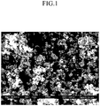
- FIG. 1 A SEM image of ⁇ -alumina nanopowders that are used as starting materials is shown in FIG. 1 .
- the ⁇ -alumina nanopowder primarily comprises distinct, individual ⁇ -alumina nanoparticles rather than agglomerated particles.
- the ⁇ -alumina nanoparticles exhibit excellent thermal stability and maintain the pore structure of the membrane.
- the average diameter of the ⁇ -alumina nanopowders shown in FIG. 1 is about 30 nm, as determined by particle size analysis of the SEM image and BET surface area measurements.
- the surface area of the particles shown in FIG. 1 measured using the BET method, is 55 m 2 /g.
- X-Ray diffraction (XRD) measurements show that the alumina powder is primarily ⁇ -alumina.
- the membrane is deposited on a support surface or substrate that has a pore size that is substantially larger than the pore size of the membrane.
- the support surface or substrate may have a pore size that is at least two times greater than that of the membrane.
- the support structure or substrate is a geometric structure comprising monolithic channels, each of which has a diameter of less than about 2 mm.
- the underlying support structure or substrate preferably has greater chemical and thermal stability than the membrane. While support structures or substrates comprising ⁇ -alumina are particularly useful, other ceramic materials such as, but not limited to, mullite, may also be used.
- the membrane may be formed as a freestanding film.
- a method of making the inorganic membrane is also provided.
- a coating slip is first provided.
- coating slip describes a slurry or any other suspension comprising at least one solid and a liquid that is used to form a ceramic coating on a substrate or support.
- the coating slip is formed using ⁇ -alumina nanoparticles and nanopowders that have been previously described.
- the nanoparticles are dispersed in a solution.
- the particles are provided to an aqueous solution.
- Organic compounds and polymeric additives may also be added to the solution. Such additives minimize interaction between the ⁇ -alumina nanopowders, thus preventing agglomeration. The additives also minimize cracking of the membrane during subsequent drying.
- polyethylene glycol (PEG) is used as a polymeric binder.
- the PEG binder has a molecular weight up to about 20,000 and, in one embodiment, in a range from about 2,000 up to about 20,000.
- the molecular weight of the polymeric binder should be such that the size of the polymeric binder matches the particle size of the nanoparticles.
- the size of the polymeric binder should be sufficiently large to prevent interaction between the ⁇ -alumina nanoparticles, but not so large as to form large pores or voids upon firing of the membrane.
- the solution has a weight loading of ⁇ -alumina nanoparticles in a range from about 0.1 wt.% to about 10 wt.%.
- the solid ⁇ -alumina loading affects the thickness slip that is applied to a support or substrate; higher ⁇ -alumina concentrations tend to produce a thicker, more viscous slip, which in turn tends to produce a thicker coating and membrane.
- the coating slip is then applied to at least one surface of a support or substrate to form a coating layer.
- the support or substrate may comprise a ceramic material such as, but not limited to, ⁇ -alumina, mullite, combinations thereof, and the like.
- the support or substrate may be monolithic or, in one embodiment, comprise a plurality of channels, and may have porosity on the order of hundreds of nanometers (i.e., 100 nm - 1000 nm).
- Application of the coating slip to a substrate may be accomplished by those means widely known in the art, such as, but not limited to, dip coating, spin coating, spray coating, slip casting, forced flow coating, and the like. Any of these techniques may be performed individually or in combination with each other.
- the drying step in one embodiment, is carried out in a controlled gas environment to prevent cracking or peeling of the coating formed by the applied coating slip on the substrate.
- the controlled gas environment is one in which the content of at least one of oxygen (O 2 ) and water content is controlled.
- the oxygen content of the controlled atmosphere is typically kept to a minimum.
- the drying step may be carried out by drying the coating layer under flowing nitrogen and water, while heating the coating layer according to a temperature schedule in which the coating layer is heated from room temperature up to a maximum temperature of about 120°C, with at least one hold at a predetermined intermediate temperature (or temperatures).
- a typical heating profile and gas and water flow rates for the drying step are shown in Table 1.
- the dried coating layer is then fired at a temperature in a range from about 900°C to about to 1200°C under a controlled gas environment.
- the firing causes the ⁇ -alumina to convert to ⁇ -alumina.
- the firing removes the organic components and solidifies the membrane structure.
- Example 1 Preparation of coating slips comprising of ⁇ -alumina and polyethylene glycol
- the general procedure for preparing coating slips is as follows. In subsequent examples, the same procedure is used to prepare coating slips having different concentrations of ⁇ -alumina and polyethylene glycol, ⁇ -alumina nanopowders having different mean particle sizes, and different molecular weights of polyethylene glycol.
- Aqueous solutions containing 4.5 wt.% PEG polyethylene glycol, 2,000 MW or 20,000 MW were prepared and stirred for at least one hour to ensure complete solution.
- Slips were made by adding 1g of ⁇ -alumina powder to 50 g of the PEG solution and 50 g ultra-pure (18 M ⁇ ) water, along with 2 drops of 1 wt.% DC-B antifoam agent.
- the morphology of the ⁇ -alumina starting material is shown in FIG. 1 .
- the average diameter of the ⁇ -alumina nanoparticles seen in FIG. 1 is about 30 nm, as determined by particle size analysis of the SEM image and BET surface area measurements. A small amount of large spherically shaped particles having a size of about 100 nm are also observed.
- the surface area of the particles shown in FIG. 1 measured using the BET method, is 55 m 2 /g. XRD measurements show that the alumina powder is primarily ⁇ -alumina.
- Each slip was hand-shaken until well-mixed, and placed in an ice bath to chill. The slip was then shaken again and agitated in six 10-second bursts, with a 10 second pause between bursts, using an ultrasonic horn set at 80%. The slip was then de-gassed by pulling a vacuum on a 150 mL filter flask for 15 minutes, or until bubbling stopped, and gently transferred to a beaker for coating application.
- Example 2 Coating of substrates and formation of ⁇ -alumina membrane onto monolithic channels
- monolithic alumina substrates were coated with monolithic alumina substrates of 10 mm diameter. Monolithic substrates of 10 mm diameter were cut to lengths of either 3 inches (7.62 cm) or 6 inches (15.24 cm). Each substrate had 19 through channels. Each of the through channels had a diameter of 0.75 mm. The substrates were flushed with water to remove debris, and then dried overnight at 60°C in air.
- Slips prepared according to the procedure described in Example 1 were used to coat substrates using a flow coater apparatus, with a 10 second soak time. Prior to coating, the pH value of each slip was adjusted to 3.2 using acetic acid.
- the coated substrate was dried in water vapor (1.8mL/hr) and N 2 gas (1L/min) with a temperature ramp of 10°C/hr to 120°C. Each coated substrate was held at 120°C for about two hours and then cooled in nitrogen gas.
- the dried sample was calcined/fired at 900°C and 1200°C for two hours in flowing 1% oxygen in N 2 with a temperature ramp of 2°C/min to form the membranes.
- Example 3 Thermal stability of ⁇ -alumina membranes
- two pre-coating layers were deposited on the substrate such that the pre-coating is disposed between the membrane and substrate.
- Slips comprising 1 wt.% of ⁇ -alumina and 2.3 wt.% PEG having molecular weights of either 2,000 MW or 20,000 MW were used to coat an ⁇ -alumina substrate with two layers of progressively finer ⁇ -alumina pre-coatings.
- the pore size of the last ⁇ -alumina pre-coating layer was several hundred nanometers.
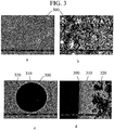
- FIGS. 2a-c and 3a-c show SEM images of the surfaces and cross-sections of membranes fired at 900°C and 1200°C, respectively.
- Membrane 300, pre-coating 310, and substrate 320 are shown at various magnifications in FIGS. 2a-c and 3a-c.
- the thickness of membrane 300 is about 3 ⁇ m and the pore size is about 20 nm.
- the particle sizes in the membranes do not exhibit any apparent increase compared with the original ⁇ -alumina particles.
- X-Ray diffraction patterns obtained for the membrane indicate that the membrane to a mixture of ⁇ -alumina and ⁇ -alumina after firing at 900°C. After firing at 1200°C, the membrane had been transformed mostly to the ⁇ -alumina phase.
- Example 4 Comparative example: thermal stability of ⁇ -Al 2 O 3
- FIGS. 4a and 4b are SEM images showing changes in ⁇ -Al 2 O 3 membrane morphology after being heated to 900°C and 1200°C, respectively.
- the average particle size of as-deposited ⁇ -Al 2 O 3 is usually about several nm in diameter.
- FIG. 5b shows these particles tend to agglomerate.
- FIG. 5b After heating at 900°C, the particles within the agglomerates start to sinter to form larger particles ( ⁇ 30 nm), shown in FIG. 5b . This sintering results in the formation of line cracks 10 on the membrane, as seen in FIG. 5a . Further heating at 1200°C ( FIG. 6a-c ) causes severe sintering ( FIG. 6c ), which can be seen in as coarsening of the surface in FIG. 6a , and complete reconstruction of the membrane surface ( FIG. 6b ).
- FIG. 7 Results of the water permeability tests on these membranes and the CCIC membrane are shown in FIG. 7 .
- Membranes fired at 900°C and 1200°C exhibited greater permeability than the CCIC membrane.
- the permeability of the membranes prepared according to the procedures described herein remained essentially constant with increasing time on stream, whereas the permeability of the CCIC membrane decreased over time.
- the permeability of the membrane fired at 1200°C is about 25% less than that of the membrane fired at 900°C, indicating that firing at the higher temperature produced a higher degree of sintering.
- the thickness of the ⁇ -alumina membrane coating was studied as a function of ⁇ -alumina concentration in the coating slip.
- Membranes were prepared according to the procedures described in Examples 1 and 2. Three coating slips, having ⁇ -alumina concentrations of 0.5 wt.%, 0.7 wt.%, and 1.0 wt.%, respectively, were used to prepare the membranes. SEM images of the resulting membranes are shown in FIGS. 9a-c . The images show that the thickness of the coating membrane may be controlled by changing the ⁇ -Al 2 O 3 concentration in the coating slip. When the ⁇ -Al 2 O 3 concentration in the coating slip is 1.0 wt.%, the thickness of the membrane 20 is about 4 ⁇ m ( FIG. 9a ).
- a membrane having a thickness of 3 ⁇ m is obtained when the ⁇ -Al 2 O 3 concentration in the coating slip is 0.7 wt.%, ( FIG. 9b ).
- a further decrease of the ⁇ -Al 2 O 3 concentration in the coating slip to 0.5 wt.% yields a membrane thickness of 2 ⁇ m ( FIG. 9c ).
- Thicker membranes have lower permeability and are more susceptible to cracking. If, on the other hand, the membrane is too thin, pinhole defects are more likely to occur.
- Optimization of ultrafiltration membrane thickness depends on the roughness of the substrate. Based on the examples described herein, the optimal thickness of an ultrafiltration membrane of the present invention is about 2 ⁇ 3 ⁇ m.
- Membrane thickness may be controlled by changing the ⁇ -Al 2 O 3 concentration in the coating slip.
- Coating slips containing ⁇ -alumina powder were prepared using the procedures described in Examples 1 and 2.
- the coating slips had pH values of 3.2, 3.5, and 3.9, respectively.
- SEM images of the membrane coatings deposited using coating slips having pH values of 3.2, 3.5, and 3.9 are shown in FIGS. 10a, b, and c , respectively. The results indicate that crack-free membranes are more easily formed when the pH of the coating slip is less than 3.5.
- a ⁇ -alumina membrane was prepared using ⁇ -alumina powder having a particle size of 19 nm.
- SEM images of the surface and particle morphologies of the dried (at 120°C) membrane prepared using 19 nm ⁇ -alumina powder are shown in FIG. 11a-c .
- SEM images of the membrane after heating at 1200°C are shown in FIG. 12a-c .
- the particle size distribution in slips prepared with ⁇ -alumina powder was measured as a function of PEG molecular weight and concentration.
- Aqueous solutions comprising 1 wt.% ⁇ -alumina and polyethylene glycol having molecular weights (MW) of 600, 900, 2,000, and 20,000 were prepared in the same manner as previously described in Example 1.
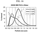
- Particle size distributions obtained using light-scattering measurements are shown in FIGS. 13 , 14 , 15 , and 16 for polyethylene glycol having 600 MW, 900 MW, 2,000 MW, and 20,000 MW, respectively.
- PEG concentrations 1.2 wt.%, 2.3 wt.%, and 4.5 wt.% were prepared.
- the shapes of the size distribution peaks are an indication of the polymeric number (i.e., the number of particles that are agglomerated together) of the alumina particles.
- the 4.5 wt% PEG slip (curve (3) in FIGS. 13-16 ) particle size distribution has a maximum at a larger particle size than the particle size distribution obtained for 1.2 wt.% (curve (1) in FIGS. 13-16 ) PEG slip, and the shapes of the particle size distributions obtained for 1.2 wt.% and 2.3 wt.% PEG concentrations appear to be polydisperse.
- FIG. 13 , 14 , and 16 PEG MWs of 600, 900 and 20,000
- the 4.5 wt% PEG slip (curve (3) in FIGS. 13-16 ) particle size distribution has a maximum at a larger particle size than the particle size distribution obtained for 1.2 wt.% (curve (1) in FIGS. 13-16 ) PEG slip, and the shapes of the particle size distributions obtained for 1.2 w
- the 4.5 wt% PEG slip particle size distribution has a maximum at 0.8 ⁇ m
- the 1.2 wt.% PEG slip size distribution has a maximum at 0.4 ⁇ m
- dimers i.e., an agglomerate comprising two particles
- the results therefore indicate that slips prepared using 2,000 MW PEG are most effective in providing mono-dispersed ⁇ -alumina particles within the largest concentration window.
Landscapes
- Chemical & Material Sciences (AREA)
- Inorganic Chemistry (AREA)
- Chemical Kinetics & Catalysis (AREA)
- Engineering & Computer Science (AREA)
- Manufacturing & Machinery (AREA)
- Separation Using Semi-Permeable Membranes (AREA)
- Compounds Of Alkaline-Earth Elements, Aluminum Or Rare-Earth Metals (AREA)
Claims (4)
- Méthode de préparation d'une membrane inorganique comprenant de l'a-alumine, la méthode comprenant les étapes consistant à :a. fournir une sauce de couchage, la sauce de couchage comprenant de la δ-alumine, la δ-alumine ayant une taille de particules moyenne dans la plage allant de 10 nm à 100 nm ;b. appliquer la sauce de couchage à une surface de support afin de former une couche de revêtement ;c. sécher la couche de revêtement ; etd. cuire la couche de revêtement séchée à une température d'au moins 1000°C afin de convertir au moins une portion de la δ-alumine en α-alumine et former la membrane inorganique, où la membrane possède une structure de pores ayant une taille de pores moyenne allant jusqu'à 100 nm et l'α-alumine possédant une taille de particules moyenne dans la plage allant de 10 nm à 100 nm, où la structure de pores est stable jusqu'à 1400°C.
- Méthode selon la revendication 1, dans laquelle l'étape de fourniture de la sauce de couchage comprend la préparation d'une solution aqueuse comprenant de 0,1% en poids à 10% en poids de δ-alumine et de 1% en poids à 10% en poids d'au moins un additif organique, où le au moins un additif organique comprend un liant polymère.
- Méthode selon la revendication 2, dans laquelle le liant polymère est constitué de polyéthylène glycol.
- Méthode selon la revendication 1, dans laquelle l'étape d'application de la sauce de couchage à une surface de support afin de former la couche de revêtement comprend l'application de la sauce de couchage à une surface de support par l'un(e) parmi un revêtement par immersion, un revêtement par glissement, une coulée en barbotine, et un revêtement à écoulement forcé afin de former la couche de revêtement.
Applications Claiming Priority (3)
| Application Number | Priority Date | Filing Date | Title |
|---|---|---|---|
| US90363707P | 2007-02-27 | 2007-02-27 | |
| US11/894,065 US8393478B2 (en) | 2007-02-27 | 2007-08-20 | Inorganic membranes and method of making |
| PCT/US2008/002157 WO2008106028A1 (fr) | 2007-02-27 | 2008-02-19 | Membranes inorganiques, et procédé de fabrication |
Publications (2)
| Publication Number | Publication Date |
|---|---|
| EP2117687A1 EP2117687A1 (fr) | 2009-11-18 |
| EP2117687B1 true EP2117687B1 (fr) | 2018-12-12 |
Family
ID=39415392
Family Applications (1)
| Application Number | Title | Priority Date | Filing Date |
|---|---|---|---|
| EP08725756.4A Ceased EP2117687B1 (fr) | 2007-02-27 | 2008-02-19 | Procédé de fabrication de membranes inorganiques |
Country Status (5)
| Country | Link |
|---|---|
| US (1) | US8393478B2 (fr) |
| EP (1) | EP2117687B1 (fr) |
| JP (2) | JP5329440B2 (fr) |
| CN (1) | CN101622059B (fr) |
| WO (1) | WO2008106028A1 (fr) |
Families Citing this family (17)
| Publication number | Priority date | Publication date | Assignee | Title |
|---|---|---|---|---|
| US8101010B2 (en) | 2009-05-28 | 2012-01-24 | Corning Incorporated | Gas separation module |
| US7989373B2 (en) | 2009-06-30 | 2011-08-02 | Corning Incorporated | Hermetic sealing material |
| JP5075186B2 (ja) * | 2009-10-30 | 2012-11-14 | 日本碍子株式会社 | ナノ濾過膜の製造方法 |
| JP5578609B2 (ja) * | 2010-03-31 | 2014-08-27 | 独立行政法人産業技術総合研究所 | 高強度複合ナノシート膜、それを用いた透明超撥水性膜及びその製造方法 |
| US8685144B2 (en) | 2010-11-12 | 2014-04-01 | The Texas A&M University System | System and method for efficient air dehumidification and liquid recovery |
| US8685145B2 (en) | 2010-11-12 | 2014-04-01 | The Texas A&M University System | System and method for efficient multi-stage air dehumidification and liquid recovery |
| WO2012065138A2 (fr) | 2010-11-12 | 2012-05-18 | The Texas A&M University System | Systèmes et procédés de déshumidification et de refroidissement sensible d'air à l'aide de pompe à étages multiples |
| US8685142B2 (en) | 2010-11-12 | 2014-04-01 | The Texas A&M University System | System and method for efficient air dehumidification and liquid recovery with evaporative cooling |
| WO2013031621A1 (fr) * | 2011-08-26 | 2013-03-07 | Tdk株式会社 | Membrane de séparation de gaz |
| KR101368462B1 (ko) | 2011-12-30 | 2014-03-03 | 웅진케미칼 주식회사 | 수처리용 분리막 및 그의 제조방법 |
| KR101632976B1 (ko) * | 2014-05-02 | 2016-06-23 | 주식회사 피코그램 | 양전하 물질이 코팅된 수처리용 분리막의 제조방법 |
| CN104014252B (zh) * | 2014-05-06 | 2016-02-17 | 三达膜科技(厦门)有限公司 | 一种陶瓷膜支撑体的制备方法 |
| CN108290102A (zh) | 2015-10-30 | 2018-07-17 | 康宁股份有限公司 | 多孔陶瓷过滤器及其制造方法 |
| CN105597553A (zh) * | 2016-03-17 | 2016-05-25 | 江苏久吾高科技股份有限公司 | 一种用于膜吸收过程的陶瓷膜制备方法 |
| US10661476B2 (en) | 2016-05-19 | 2020-05-26 | Cal Poly Corporation | Porous nanostructures and methods of fabrication |
| JP7187109B2 (ja) | 2017-10-31 | 2022-12-12 | コーニング インコーポレイテッド | ハニカム体、およびハニカム体を含むパティキュレートフィルタ |
| US11161782B2 (en) | 2017-11-30 | 2021-11-02 | Corning Incorporated | Method of increasing IOX processability on glass articles with multiple thicknesses |
Citations (1)
| Publication number | Priority date | Publication date | Assignee | Title |
|---|---|---|---|---|
| US4968426A (en) * | 1987-12-11 | 1990-11-06 | Norton Company | Fine alpha alumina ultrafiltration membranes |
Family Cites Families (12)
| Publication number | Priority date | Publication date | Assignee | Title |
|---|---|---|---|---|
| JPS58205504A (ja) * | 1982-05-24 | 1983-11-30 | Agency Of Ind Science & Technol | 耐熱性多孔質膜 |
| EP0327687A3 (fr) * | 1987-12-11 | 1989-11-15 | Norton Company | Membranes d'ultrafiltration |
| JPH02102723A (ja) * | 1988-10-12 | 1990-04-16 | Ngk Insulators Ltd | 無機多孔質膜 |
| US5006248A (en) | 1989-10-23 | 1991-04-09 | Wisconsin Alumni Research Foundation | Metal oxide porous ceramic membranes with small pore sizes |
| US5208190A (en) | 1991-10-08 | 1993-05-04 | Wisconsin Alumni Research Foundation | Microporous alumina ceramic membranes |
| JP3440101B2 (ja) * | 1992-01-27 | 2003-08-25 | 日本碍子株式会社 | 浄水器用セラミック膜フィルタ |
| US6464881B2 (en) | 1996-10-21 | 2002-10-15 | Orelis | Inorganic nanofiltration membrane and its application in the sugar industry |
| US6225246B1 (en) | 1996-11-12 | 2001-05-01 | National Research Council Of Canada | Functionally gradient ceramic structures |
| US6649255B1 (en) | 1999-03-04 | 2003-11-18 | Douglas E. Fain, Sr. | Article and method for producing extremely small pore inorganic membranes |
| DE19922492A1 (de) | 1999-05-14 | 2000-11-16 | Fraunhofer Ges Forschung | Verfahren zur Herstellugn von Aluminiumoxiden und daraus hergestellten Produkten |
| JP2004089838A (ja) * | 2002-08-30 | 2004-03-25 | Kyocera Corp | 分離膜モジュール及びその製造方法 |
| WO2006034717A1 (fr) | 2004-09-29 | 2006-04-06 | Danmarks Tekniske Universitet | Procede pour la preparation d'une membrane asymetrique comprenant un substrat mesoporeux ou macroporeux et une couche microporeuse/mesoporeuse deposee dessus et membrane asymetrique |
-
2007
- 2007-08-20 US US11/894,065 patent/US8393478B2/en active Active
-
2008
- 2008-02-19 EP EP08725756.4A patent/EP2117687B1/fr not_active Ceased
- 2008-02-19 JP JP2009551675A patent/JP5329440B2/ja not_active Expired - Fee Related
- 2008-02-19 CN CN200880006026.XA patent/CN101622059B/zh not_active Expired - Fee Related
- 2008-02-19 WO PCT/US2008/002157 patent/WO2008106028A1/fr not_active Ceased
-
2013
- 2013-06-05 JP JP2013118705A patent/JP5524393B2/ja active Active
Patent Citations (1)
| Publication number | Priority date | Publication date | Assignee | Title |
|---|---|---|---|---|
| US4968426A (en) * | 1987-12-11 | 1990-11-06 | Norton Company | Fine alpha alumina ultrafiltration membranes |
Non-Patent Citations (1)
| Title |
|---|
| W. GERHARTZ (ED.): "ULLMANN'S ENCYCLOPEDIA OF INDUSTRIAL CHEMISTRY", vol. A1, 1985, VCH VERLAGSGESELLSCHAFT MBH, Weinheim, ISBN: 3-527-20101-7, pages: 561 - 562 * |
Also Published As
| Publication number | Publication date |
|---|---|
| JP5329440B2 (ja) | 2013-10-30 |
| JP5524393B2 (ja) | 2014-06-18 |
| JP2013176771A (ja) | 2013-09-09 |
| CN101622059B (zh) | 2013-07-10 |
| WO2008106028A1 (fr) | 2008-09-04 |
| JP2010527747A (ja) | 2010-08-19 |
| CN101622059A (zh) | 2010-01-06 |
| US8393478B2 (en) | 2013-03-12 |
| US20120132584A1 (en) | 2012-05-31 |
| EP2117687A1 (fr) | 2009-11-18 |
Similar Documents
| Publication | Publication Date | Title |
|---|---|---|
| EP2117687B1 (fr) | Procédé de fabrication de membranes inorganiques | |
| Kim et al. | Sol-gel synthesis and characterization of yttria stabilized zirconia membranes | |
| CN102762279B (zh) | 涂覆的颗粒过滤器和方法 | |
| JP5302957B2 (ja) | 特定の気孔形成剤を用いて多孔質支持体に無機多孔質被膜を形成する方法 | |
| Van Gestel et al. | Alumina and titania multilayer membranes for nanofiltration: preparation, characterization and chemical stability | |
| US20190161415A1 (en) | Cordierite membrane on a cordierite monolith | |
| JP5990186B2 (ja) | アルミナセラミック膜 | |
| US4971696A (en) | Inorganic porous membrane | |
| Vacassy et al. | Synthesis and characterization of microporous zirconia powders: application in nanofilters and nanofiltration characteristics | |
| Chowdhury et al. | Pore size and surface chemistry effects on the transport of hydrophobic and hydrophilic solvents through mesoporous γ-alumina and silica MCM-48 | |
| Burggraaf et al. | Synthesis of inorganic membranes | |
| CN102171166A (zh) | 无机膜的制造方法 | |
| Etienne et al. | A microporous zirconia membrane prepared by the sol—gel process from zirconyl oxalate | |
| JP2008012527A (ja) | 触媒担持粒子およびそれを用いた触媒体の製造方法 | |
| AU631493B2 (en) | A porous inorganic composite semipermeable membrane and a method of preparation | |
| US5030351A (en) | Process for the preparation of a binary membrane top layer | |
| Krell et al. | Performance of alumina membranes from new nanosynthesis in ultrafiltration and nanofiltration | |
| JPH0243928A (ja) | 無機多孔質膜 | |
| JP2002274967A (ja) | γアルミナ質多孔体およびその製造方法並びにこれを用いた流体分離フィルタ | |
| CN114502263A (zh) | 用于水处理和废水处理的陶瓷膜 | |
| Othman et al. | Review on development of ceramic membrane from sol-gel route: parameters affecting characteristics of the membrane | |
| Hofman-Züter et al. | Coating of sol particles for membrane applications | |
| Kwon et al. | Sol–Gel Synthesis and Characterization of Nanostructured TiO2/γ-Al2O3 Composite Membranes | |
| Kim et al. | Sol-gel synthesis and characterization of yttria | |
| Vityaz et al. | Foams & Porous Materials: Submicrometer Pore Size Multilayer Ceramic Membrane Filters |
Legal Events
| Date | Code | Title | Description |
|---|---|---|---|
| PUAI | Public reference made under article 153(3) epc to a published international application that has entered the european phase |
Free format text: ORIGINAL CODE: 0009012 |
|
| 17P | Request for examination filed |
Effective date: 20090326 |
|
| AK | Designated contracting states |
Kind code of ref document: A1 Designated state(s): AT BE BG CH CY CZ DE DK EE ES FI FR GB GR HR HU IE IS IT LI LT LU LV MC MT NL NO PL PT RO SE SI SK TR |
|
| AX | Request for extension of the european patent |
Extension state: AL BA MK RS |
|
| 17Q | First examination report despatched |
Effective date: 20100129 |
|
| DAX | Request for extension of the european patent (deleted) | ||
| RBV | Designated contracting states (corrected) |
Designated state(s): DE FR GB NL |
|
| GRAJ | Information related to disapproval of communication of intention to grant by the applicant or resumption of examination proceedings by the epo deleted |
Free format text: ORIGINAL CODE: EPIDOSDIGR1 |
|
| GRAP | Despatch of communication of intention to grant a patent |
Free format text: ORIGINAL CODE: EPIDOSNIGR1 |
|
| INTG | Intention to grant announced |
Effective date: 20180626 |
|
| GRAS | Grant fee paid |
Free format text: ORIGINAL CODE: EPIDOSNIGR3 |
|
| GRAA | (expected) grant |
Free format text: ORIGINAL CODE: 0009210 |
|
| AK | Designated contracting states |
Kind code of ref document: B1 Designated state(s): DE FR GB NL |
|
| REG | Reference to a national code |
Ref country code: GB Ref legal event code: FG4D |
|
| REG | Reference to a national code |
Ref country code: DE Ref legal event code: R096 Ref document number: 602008058298 Country of ref document: DE |
|
| REG | Reference to a national code |
Ref country code: NL Ref legal event code: FP |
|
| REG | Reference to a national code |
Ref country code: DE Ref legal event code: R097 Ref document number: 602008058298 Country of ref document: DE |
|
| PLBE | No opposition filed within time limit |
Free format text: ORIGINAL CODE: 0009261 |
|
| STAA | Information on the status of an ep patent application or granted ep patent |
Free format text: STATUS: NO OPPOSITION FILED WITHIN TIME LIMIT |
|
| 26N | No opposition filed |
Effective date: 20190913 |
|
| PGFP | Annual fee paid to national office [announced via postgrant information from national office to epo] |
Ref country code: NL Payment date: 20200130 Year of fee payment: 13 |
|
| REG | Reference to a national code |
Ref country code: NL Ref legal event code: MM Effective date: 20210301 |
|
| PG25 | Lapsed in a contracting state [announced via postgrant information from national office to epo] |
Ref country code: NL Free format text: LAPSE BECAUSE OF NON-PAYMENT OF DUE FEES Effective date: 20210301 |
|
| P01 | Opt-out of the competence of the unified patent court (upc) registered |
Effective date: 20230527 |
|
| PGFP | Annual fee paid to national office [announced via postgrant information from national office to epo] |
Ref country code: DE Payment date: 20240109 Year of fee payment: 17 Ref country code: GB Payment date: 20240111 Year of fee payment: 17 |
|
| PGFP | Annual fee paid to national office [announced via postgrant information from national office to epo] |
Ref country code: FR Payment date: 20240108 Year of fee payment: 17 |
|
| REG | Reference to a national code |
Ref country code: DE Ref legal event code: R119 Ref document number: 602008058298 Country of ref document: DE |
|
| GBPC | Gb: european patent ceased through non-payment of renewal fee |
Effective date: 20250219 |
|
| PG25 | Lapsed in a contracting state [announced via postgrant information from national office to epo] |
Ref country code: DE Free format text: LAPSE BECAUSE OF NON-PAYMENT OF DUE FEES Effective date: 20250902 |
|
| PG25 | Lapsed in a contracting state [announced via postgrant information from national office to epo] |
Ref country code: GB Free format text: LAPSE BECAUSE OF NON-PAYMENT OF DUE FEES Effective date: 20250219 |
|
| PG25 | Lapsed in a contracting state [announced via postgrant information from national office to epo] |
Ref country code: FR Free format text: LAPSE BECAUSE OF NON-PAYMENT OF DUE FEES Effective date: 20250228 |