EP2117910B1 - Boîte de transfert pour transférer des mouvements de changement de vitesse dans un véhicule - Google Patents
Boîte de transfert pour transférer des mouvements de changement de vitesse dans un véhicule Download PDFInfo
- Publication number
- EP2117910B1 EP2117910B1 EP07701105A EP07701105A EP2117910B1 EP 2117910 B1 EP2117910 B1 EP 2117910B1 EP 07701105 A EP07701105 A EP 07701105A EP 07701105 A EP07701105 A EP 07701105A EP 2117910 B1 EP2117910 B1 EP 2117910B1
- Authority
- EP
- European Patent Office
- Prior art keywords
- lever
- transfer box
- portions
- frame portion
- bearing
- Prior art date
- Legal status (The legal status is an assumption and is not a legal conclusion. Google has not performed a legal analysis and makes no representation as to the accuracy of the status listed.)
- Not-in-force
Links
- 230000000694 effects Effects 0.000 description 2
- 230000009286 beneficial effect Effects 0.000 description 1
- 230000001419 dependent effect Effects 0.000 description 1
- 230000001627 detrimental effect Effects 0.000 description 1
- 238000004519 manufacturing process Methods 0.000 description 1
- 238000012986 modification Methods 0.000 description 1
- 230000004048 modification Effects 0.000 description 1
Images

Classifications
-
- B—PERFORMING OPERATIONS; TRANSPORTING
- B62—LAND VEHICLES FOR TRAVELLING OTHERWISE THAN ON RAILS
- B62D—MOTOR VEHICLES; TRAILERS
- B62D33/00—Superstructures for load-carrying vehicles
- B62D33/06—Drivers' cabs
- B62D33/063—Drivers' cabs movable from one position into at least one other position, e.g. tiltable, pivotable about a vertical axis, displaceable from one side of the vehicle to the other
- B62D33/073—Drivers' cabs movable from one position into at least one other position, e.g. tiltable, pivotable about a vertical axis, displaceable from one side of the vehicle to the other characterised by special adaptations of vehicle control devices
-
- F—MECHANICAL ENGINEERING; LIGHTING; HEATING; WEAPONS; BLASTING
- F16—ENGINEERING ELEMENTS AND UNITS; GENERAL MEASURES FOR PRODUCING AND MAINTAINING EFFECTIVE FUNCTIONING OF MACHINES OR INSTALLATIONS; THERMAL INSULATION IN GENERAL
- F16H—GEARING
- F16H59/00—Control inputs to control units of change-speed- or reversing-gearings for conveying rotary motion
- F16H59/02—Selector apparatus
- F16H59/0208—Selector apparatus with means for suppression of vibrations or reduction of noise
-
- F—MECHANICAL ENGINEERING; LIGHTING; HEATING; WEAPONS; BLASTING
- F16—ENGINEERING ELEMENTS AND UNITS; GENERAL MEASURES FOR PRODUCING AND MAINTAINING EFFECTIVE FUNCTIONING OF MACHINES OR INSTALLATIONS; THERMAL INSULATION IN GENERAL
- F16H—GEARING
- F16H59/00—Control inputs to control units of change-speed- or reversing-gearings for conveying rotary motion
- F16H59/02—Selector apparatus
- F16H59/04—Ratio selector apparatus
-
- F—MECHANICAL ENGINEERING; LIGHTING; HEATING; WEAPONS; BLASTING
- F16—ENGINEERING ELEMENTS AND UNITS; GENERAL MEASURES FOR PRODUCING AND MAINTAINING EFFECTIVE FUNCTIONING OF MACHINES OR INSTALLATIONS; THERMAL INSULATION IN GENERAL
- F16H—GEARING
- F16H61/00—Control functions within control units of change-speed- or reversing-gearings for conveying rotary motion ; Control of exclusively fluid gearing, friction gearing, gearings with endless flexible members or other particular types of gearing
- F16H61/26—Generation or transmission of movements for final actuating mechanisms
-
- Y—GENERAL TAGGING OF NEW TECHNOLOGICAL DEVELOPMENTS; GENERAL TAGGING OF CROSS-SECTIONAL TECHNOLOGIES SPANNING OVER SEVERAL SECTIONS OF THE IPC; TECHNICAL SUBJECTS COVERED BY FORMER USPC CROSS-REFERENCE ART COLLECTIONS [XRACs] AND DIGESTS
- Y10—TECHNICAL SUBJECTS COVERED BY FORMER USPC
- Y10T—TECHNICAL SUBJECTS COVERED BY FORMER US CLASSIFICATION
- Y10T74/00—Machine element or mechanism
- Y10T74/20—Control lever and linkage systems
- Y10T74/20012—Multiple controlled elements
- Y10T74/20018—Transmission control
- Y10T74/2014—Manually operated selector [e.g., remotely controlled device, lever, push button, rotary dial, etc.]
Definitions
- the present invention relates to a transfer box for transferring movements and forces from a tiltable cab portion of a heavy vehicle to a gearbox, mounted in its chassis.
- the transfer box comprises a first frame portion mounted on the cab portion, and comprises at least one lever portion journalled on at least one bearing.
- the lever portion is connected to cable ends or push rods connected to a gear shift lever.
- a second frame portion is mounted on the vehicle chassis and comprises at least one second lever portion journalled on at least one bearing and connected to cable ends or pushrods connected to a gearbox.
- the first lever portions and the second lever portions interact to enable transfer of movements and force from the cable ends or push rods connected to the first lever portions to the cable ends or push rods connected to the second lever portions.
- EP 0999 084 A2 discloses a transfer box according to the preamble of claim 1.
- a cab mounted on top of the engine compartment i.e. a so called cab-over or COE (Cab Over Engine) design.
- COE Car Over Engine
- the tilting function does pose complications, mainly when it comes to transfer of driver commands to the components mounted in the chassis, such as steering wheel movements to the steering wheels, clutch pedal commands to the clutch, brake pedal movements to the brakes, and gearshift lever movements to the gearbox.
- This invention is mainly directed towards a transfer box enabling low friction transfer of gearshift lever movements to the gearbox.
- cab in most cases is resiliently suspended from the chassis; in order not to transfer chassis vibrations to the cab, it is advantageous if all connections between the cab and the chassis are resiliently suspended from the chassis.
- the main drawbacks with the pushrod systems are, firstly, that vibrations from the gearbox and chassis are transmitted to the gearshift lever, and secondly, that adjustments of the gearshift lever position vs. the actual gear position are difficult. Moreover, it might be necessary to dismount the pushrods prior to a cab tilting operation or to use a design where the pushrods system is separable, such as described in EP 34 21 74 .
- the internal friction is a detrimental for the force required for shifting gear, the "feel" of shifting gear and, lastly, the speed to shift gear.
- the second frame portion is suspended from the chassis by at least one resilient member, e.g. a spring.
- alignment means could be connected to first and second frame portions, respectively.
- lever portions could be journalled on ball bearings.
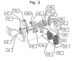
- a dividable transfer box 100 is shown in an open position.
- the transfer box 100 comprises first and second upper lever portions 130, 140, which are connectable to first and second lower lever portions 210, 220, respectively, in a way that will be described below.
- first and second upper lever portions 130, 140 are connected to the first and second lower lever portions 210, 220, which in turn are connected to pushrods or cables (not shown).
- the pushrods or cables are connected to control levers (not shown) of a gearbox (not shown). Movements of the push rods or cables will effect gear changes of the gearbox, in a way well known to persons skilled in the art, thus transferring preferably two dimensional movements of the control lever to the gearbox.
- the upper first and second lever portions 130, 140 are shown mounted in a first frame portion 150.
- the upper first and second lever portions 130, 140 are journalled in bearings 130', 140', which are fastened to the frame portion 150 and allows rotation of the upper first and second lever portions 130, 140.
- the upper first and second lever portions 130, 140 are provided with connection means 130a, 140a for connecting to first and second cable or pushrod ends (not shown).
- ends of the first and second upper lever portions 130, 140 are formed as connecting wedges 140b (the wedge of first lever portion 130 is hidden by bearing 140' in Fig. 2 ).
- a cone shaped member 160 of an alignment means could be included in the first frame portion 150.
- first and second lower lever portions 210, 220 are shown.
- the first and second lower lever portions 210, 220 are journalled in bearings 210', 220', which in turn are fastened to a second frame portion 250.
- An alignment member 260 comprising a cone shaped opening 260', whose shape corresponds to the shape of the cone shaped member 160 of the first frame portion 150 could be fastened to the second frame portion 150.
- the frame portion is preferably fastened to a vehicle chassis by means of two resilient members 280, 290, such as coil springs. These springs accommodate movements between the chassis and the cab portion, which movements primarily emanates from the fact that most cab portions are suspended from the chassis, but may also emanate from manufacturing tolerances.
- the first and second lower lever portions 210, 220 are provided with means for connection, 230a, 240a to the push rods or cables (not shown). Moreover, they are each provided with wedge shaped openings 230b, 240b, whose shape corresponds to the shape of the connecting wedges 140b, respectively (the wedge of first lever portion 130 is hidden by bearing 140' in Fig. 2 ).
- the invention aims to solve the problem with transfer of gearshift movements from a gear lever mounted in a tiltable cab (not shown) of the vehicle and the gearbox, which usually is mounted within the vehicle chassis.
- the second frame portion 250 is mounted on the vehicle chassis, as mentioned suspended by the springs 280, 290, and the first frame portion 150 is mounted on the tiltable cab such that the bearings 130', 210', 140' and 220' are aligned, i.e. such that the centre axes of the bearings 130' and 140' are aligned with the centre axes of the bearings 210', 220', respectively, whenever the cab portion is in an untilted position.
- the connecting wedges 140b (the wedge of first lever portion 130 is hidden by bearing 140' in Fig. 2 ) will engage the wedge shaped openings 230b, 240b of the first and second lower lever portions 210, 220.
- This engagement makes the first and second lower lever portions 210, 220 and the upper first and second lever portions 130, 140 move as two separate levers, wherein the first separate lever comprises the upper lever portion 130 and the lower lever portion 210, and wherein the second separate lever comprises the upper lever portion 140 and the lower lever portion 220.
- connection means 130a, 140a there will be a transfer of movement and force through the separate levers; a force or movement exerted on either of the connection means 130a, 140a will, due to the rotatable mounting of the levers in the bearings 130', 210', 140' and 220' be transferred to the push rods or cables (not shown) connected at lower connection means 230a and 240a, meaning that a movement of the gear lever in the cab will be transferred to the gearbox, and effect a gear shift.
- the connecting wedges 140b (the wedge of first lever portion 130 is hidden by bearing 140' in Fig. 2 ) and the wedge shaped openings 230b, 240b will disengage from one another and hence enable the cab to be tilted.
- the cab is tilted back to its driving position.
- the wedge shape of the connecting wedges and the wedge shaped openings of the lever portions is very beneficial; if the gear shift lever in the cab would move during the time the cab is tilted (which, by the way, is likely to happen), then the mutual position between the first and second lower lever portions 210, 220 and the upper first and second lever portions 130, 140, respectively, will change. Due to the wedge shape, such misalignment will however be adjusted automatically, since the tip of the connection wedges, if misaligned, will be guided by the walls of the wedge shaped openings until the connecting wedges 140b (the wedge of first lever portion 130 is hidden by bearing 140' in Fig. 2 ) are properly housed within the wedge shaped openings 230b, 240b. This will guarantee a proper adjustment of the gearshift lever vs. the gearbox, even after a tilting/untilting operation of the cab portion.
- said wedge shaped openings and the corresponding connecting wedges could be formed even more in a Y-shape instead of V-shape as showed in the figures.
- a Y-shape would have the above mentioned benefits of the V-shape and additionally the benefit of a more secure connection.
Landscapes
- Engineering & Computer Science (AREA)
- Mechanical Engineering (AREA)
- General Engineering & Computer Science (AREA)
- Chemical & Material Sciences (AREA)
- Combustion & Propulsion (AREA)
- Transportation (AREA)
- Gear-Shifting Mechanisms (AREA)
- Arrangement Or Mounting Of Control Devices For Change-Speed Gearing (AREA)
Abstract
Claims (8)
- Boîte de transfert (100) pour transférer des mouvements et des forces provenant d'un levier de changement de vitesse d'une partie de cabine basculante d'un véhicule lourd à une boîte de vitesses montée dans son châssis, la boîte de transfert (100) comprenant :une première partie de cadre (150) montée sur la partie de cabine, la première partie de cadre (150) comprenant au moins une première partie de levier (130, 140) tourillonnée sur au moins un premier palier (130', 140') et pouvant être reliée à des extrémités de câble ou des tiges de poussée reliées au levier de changement de vitesse,une seconde partie de cadre (250) montée sur le châssis du véhicule, caractérisée en ce que la seconde partie de cadre (250) comprend au moins une seconde partie de levier (210, 220) tourillonnée sur au moins un second palier (210', 220') et pouvant être reliée à des extrémités de câble ou des tiges de poussée reliées à une boîte de vitesses,en ce que la au moins une première partie de levier (130, 140) et la au moins une seconde partie de levier (210, 220) coopèrent et forment au moins un levier séparé permettant un transfert de mouvements et de force provenant des extrémités de cable ou des tiges de poussées pouvant être reliées à la au moins une première partie de levier (130, 140) ou aux extrémités de câble ou tiges de poussée pouvant être reliées à la au moins une seconde partie de levier (210, 220) lorsque la boîte de transfert est dans une position de fonctionnement,la au moins une première et la au moins une seconde parties de levier (130, 140, 210, 220) sont munies de parties complémentaires (140b, 230b, 240b) comprenant un coin (140b) agencé sur le au moins un premier levier (130, 140) et une ouverture en forme de coin (230b, 240b) agencée sur le au moins un second levier (210, 220), et en ce qu'un axe central du au moins un premier palier (130') est aligné avec un axe central du au moins un second palier (210', 220').
- Boîte de transfert (100) selon la revendication 1, dans laquelle le coin (140b) et l'ouverture en coin correspondante (230b, 240b) sont formés principalement selon une forme de Y.
- Boîte de transfert (100) selon la revendication 1, dans laquelle le coin (140b) et l'ouverture en coin correspondante (230b, 240b) sont formés principalement sous la forme d'un V.
- Boîte de transfert (100) selon l'une quelconque des revendications précédentes, dans laquelle la seconde partie de cadre (250) est suspendue à partir du châssis par au moins un élément élastique (280, 290).
- Boîte de transfert (100) selon la revendication 4, dans laquelle le au moins un élément élastique (280, 290) est un ressort.
- Boîte de transfert (100) selon l'une quelconque des revendications précédentes, comprenant de plus des moyens d'alignement complémentaires (160, 260) reliés aux première et seconde parties de cadre (150, 250), respectivement.
- Boîte de transfert (100) selon la revendication précédente, dans laquelle les moyens d'alignement complémentaires (160, 260) sont formés principalement selon une forme de cône.
- Boîte de transfert (100) selon l'une quelconque des revendications précédentes, dans laquelle le au moins un palier (130', 140') de la première partie de cadre (150) et le au moins un palier (210', 220') de la seconde partie de cadre (250) sont des paliers à billes, à rouleaux ou à aiguilles.
Applications Claiming Priority (1)
| Application Number | Priority Date | Filing Date | Title |
|---|---|---|---|
| PCT/SE2007/000019 WO2008085089A1 (fr) | 2007-01-12 | 2007-01-12 | Boîte de transfert pour transférer des mouvements de changement de vitesse dans un véhicule |
Publications (3)
| Publication Number | Publication Date |
|---|---|
| EP2117910A1 EP2117910A1 (fr) | 2009-11-18 |
| EP2117910A4 EP2117910A4 (fr) | 2010-09-01 |
| EP2117910B1 true EP2117910B1 (fr) | 2012-07-18 |
Family
ID=39608876
Family Applications (1)
| Application Number | Title | Priority Date | Filing Date |
|---|---|---|---|
| EP07701105A Not-in-force EP2117910B1 (fr) | 2007-01-12 | 2007-01-12 | Boîte de transfert pour transférer des mouvements de changement de vitesse dans un véhicule |
Country Status (3)
| Country | Link |
|---|---|
| US (1) | US8360194B2 (fr) |
| EP (1) | EP2117910B1 (fr) |
| WO (1) | WO2008085089A1 (fr) |
Families Citing this family (2)
| Publication number | Priority date | Publication date | Assignee | Title |
|---|---|---|---|---|
| FR2919845B1 (fr) * | 2007-08-09 | 2010-02-19 | Europ De Fabrications Ind Sefi | Systeme de commande par cable d'une boite de vitesses pour poids lourd a cabine basculante |
| US10167946B2 (en) * | 2016-05-09 | 2019-01-01 | GM Global Technology Operations LLC | Electronic transmission range selection system including a bezel with locating features |
Family Cites Families (11)
| Publication number | Priority date | Publication date | Assignee | Title |
|---|---|---|---|---|
| CS167526B1 (en) | 1972-01-10 | 1976-04-29 | Stanislav Cernoch | Gearshift mechanism for gear shifting of motor vehicles |
| FR2184218A5 (fr) | 1972-05-12 | 1973-12-21 | Berliet Automobiles | |
| FR2254197A5 (fr) | 1973-12-05 | 1975-07-04 | Berliet Automobiles | |
| DE2527407A1 (de) | 1975-06-20 | 1977-01-13 | Daimler Benz Ag | Schaltgestaenge fuer fahrzeuge, insbesondere fuer nutzkraftwagen mit kippbaren fahrerhaeusern |
| DE2613779C3 (de) | 1976-03-31 | 1981-05-07 | M.A.N. Maschinenfabrik Augsburg-Nürnberg AG, 8000 München | Schaltvorrichtung für Wechselgetriebe von Lastkraftwagen mit schwenkbarem Fahrerhaus |
| US4235299A (en) * | 1978-08-08 | 1980-11-25 | Applied Power Inc. | Gear shift connecting apparatus |
| US4206826A (en) * | 1978-11-20 | 1980-06-10 | International Harvester Company | Transmission remote shift system of the disconnect type for a cab-over chassis |
| US4269282A (en) | 1979-05-31 | 1981-05-26 | Mack Trucks, Inc. | Gear shift control |
| WO1982000809A1 (fr) | 1980-09-10 | 1982-03-18 | Power Inc Applied | Appareil d'accouplement d'une boite de vitesse |
| SE466651B (sv) | 1988-05-09 | 1992-03-16 | Volvo Ab | Vaexelmekanism i ett fordon med tippbar hytt |
| SE511597C2 (sv) | 1998-11-04 | 1999-10-25 | Volvo Lastvagnar Ab | Växelreglage för fordon |
-
2007
- 2007-01-12 EP EP07701105A patent/EP2117910B1/fr not_active Not-in-force
- 2007-01-12 US US12/522,920 patent/US8360194B2/en not_active Expired - Fee Related
- 2007-01-12 WO PCT/SE2007/000019 patent/WO2008085089A1/fr not_active Ceased
Also Published As
| Publication number | Publication date |
|---|---|
| WO2008085089A1 (fr) | 2008-07-17 |
| EP2117910A1 (fr) | 2009-11-18 |
| US8360194B2 (en) | 2013-01-29 |
| EP2117910A4 (fr) | 2010-09-01 |
| US20100147096A1 (en) | 2010-06-17 |
Similar Documents
| Publication | Publication Date | Title |
|---|---|---|
| US6854354B2 (en) | Shifting device for an automobile gearbox | |
| EP1500831B1 (fr) | Dispositif de verrouillage pour câble de commande | |
| EP2117910B1 (fr) | Boîte de transfert pour transférer des mouvements de changement de vitesse dans un véhicule | |
| EP0817926B1 (fr) | Mecanisme de commande de boite de vitesse pourvu d'un organe permettant d'actionner le cable relie au systeme de la cle de contact | |
| EP0992713B1 (fr) | Dispositif de sélection pour boite de vitesses | |
| US20100212447A1 (en) | Shifting device for a vehicle transmission | |
| US6029536A (en) | Shift lever assembly with breakable retaining member upon application of excessive force | |
| KR100892484B1 (ko) | 변속기의 시프트 록 해제 장치 | |
| JP3217341B2 (ja) | ティルト・キャブ自動車用変速機構 | |
| US6006623A (en) | Shift lever assembly | |
| US11598416B2 (en) | Interlocking device for a transmission | |
| US7832303B2 (en) | Position detection device for automatic transmission | |
| KR20030081591A (ko) | 자동 변속기의 시프트 록 장치 | |
| JPS63284032A (ja) | 変速セレクタレバー組立体 | |
| CN207261638U (zh) | 一种摩托车及其换挡操纵机构 | |
| EP0999084B1 (fr) | Dispositif de contrôle de transmission pour véhicule | |
| EP0748957A2 (fr) | Système de verrouillage de sélecteur de vitesse pour véhicule avec transmission automatique | |
| US5896777A (en) | Control lever fixing mechanism | |
| KR0125299Y1 (ko) | 중립 설정식 변속 레바 조립체 | |
| EP2892794A1 (fr) | Mécanisme de changement de vitesse pour véhicules comportant une cabine inclinable | |
| KR20260046776A (ko) | 전자식 변속조작장치 | |
| KR19990001555U (ko) | 플로워형 변속레버의 와이어 고정 구조 | |
| KR0185894B1 (ko) | 체결이 용이한 자동차 파킹 브레이크 장착용 이퀼라이저 | |
| EP0838614A1 (fr) | Dispositif de commande pour transmission véhiculaire | |
| KR19990020808U (ko) | 수동 변속기의 시프팅 장치 |
Legal Events
| Date | Code | Title | Description |
|---|---|---|---|
| PUAI | Public reference made under article 153(3) epc to a published international application that has entered the european phase |
Free format text: ORIGINAL CODE: 0009012 |
|
| 17P | Request for examination filed |
Effective date: 20090812 |
|
| AK | Designated contracting states |
Kind code of ref document: A1 Designated state(s): AT BE BG CH CY CZ DE DK EE ES FI FR GB GR HU IE IS IT LI LT LU LV MC NL PL PT RO SE SI SK TR |
|
| DAX | Request for extension of the european patent (deleted) | ||
| A4 | Supplementary search report drawn up and despatched |
Effective date: 20100730 |
|
| GRAP | Despatch of communication of intention to grant a patent |
Free format text: ORIGINAL CODE: EPIDOSNIGR1 |
|
| GRAS | Grant fee paid |
Free format text: ORIGINAL CODE: EPIDOSNIGR3 |
|
| GRAA | (expected) grant |
Free format text: ORIGINAL CODE: 0009210 |
|
| AK | Designated contracting states |
Kind code of ref document: B1 Designated state(s): AT BE BG CH CY CZ DE DK EE ES FI FR GB GR HU IE IS IT LI LT LU LV MC NL PL PT RO SE SI SK TR |
|
| REG | Reference to a national code |
Ref country code: GB Ref legal event code: FG4D |
|
| REG | Reference to a national code |
Ref country code: CH Ref legal event code: EP |
|
| REG | Reference to a national code |
Ref country code: AT Ref legal event code: REF Ref document number: 566899 Country of ref document: AT Kind code of ref document: T Effective date: 20120815 Ref country code: IE Ref legal event code: FG4D |
|
| REG | Reference to a national code |
Ref country code: DE Ref legal event code: R096 Ref document number: 602007024054 Country of ref document: DE Effective date: 20120913 |
|
| REG | Reference to a national code |
Ref country code: NL Ref legal event code: VDEP Effective date: 20120718 |
|
| REG | Reference to a national code |
Ref country code: AT Ref legal event code: MK05 Ref document number: 566899 Country of ref document: AT Kind code of ref document: T Effective date: 20120718 |
|
| REG | Reference to a national code |
Ref country code: LT Ref legal event code: MG4D Effective date: 20120718 |
|
| PG25 | Lapsed in a contracting state [announced via postgrant information from national office to epo] |
Ref country code: IS Free format text: LAPSE BECAUSE OF FAILURE TO SUBMIT A TRANSLATION OF THE DESCRIPTION OR TO PAY THE FEE WITHIN THE PRESCRIBED TIME-LIMIT Effective date: 20121118 Ref country code: AT Free format text: LAPSE BECAUSE OF FAILURE TO SUBMIT A TRANSLATION OF THE DESCRIPTION OR TO PAY THE FEE WITHIN THE PRESCRIBED TIME-LIMIT Effective date: 20120718 Ref country code: BE Free format text: LAPSE BECAUSE OF FAILURE TO SUBMIT A TRANSLATION OF THE DESCRIPTION OR TO PAY THE FEE WITHIN THE PRESCRIBED TIME-LIMIT Effective date: 20120718 Ref country code: FI Free format text: LAPSE BECAUSE OF FAILURE TO SUBMIT A TRANSLATION OF THE DESCRIPTION OR TO PAY THE FEE WITHIN THE PRESCRIBED TIME-LIMIT Effective date: 20120718 Ref country code: LT Free format text: LAPSE BECAUSE OF FAILURE TO SUBMIT A TRANSLATION OF THE DESCRIPTION OR TO PAY THE FEE WITHIN THE PRESCRIBED TIME-LIMIT Effective date: 20120718 Ref country code: CY Free format text: LAPSE BECAUSE OF FAILURE TO SUBMIT A TRANSLATION OF THE DESCRIPTION OR TO PAY THE FEE WITHIN THE PRESCRIBED TIME-LIMIT Effective date: 20120718 |
|
| PG25 | Lapsed in a contracting state [announced via postgrant information from national office to epo] |
Ref country code: PL Free format text: LAPSE BECAUSE OF FAILURE TO SUBMIT A TRANSLATION OF THE DESCRIPTION OR TO PAY THE FEE WITHIN THE PRESCRIBED TIME-LIMIT Effective date: 20120718 Ref country code: SI Free format text: LAPSE BECAUSE OF FAILURE TO SUBMIT A TRANSLATION OF THE DESCRIPTION OR TO PAY THE FEE WITHIN THE PRESCRIBED TIME-LIMIT Effective date: 20120718 Ref country code: PT Free format text: LAPSE BECAUSE OF FAILURE TO SUBMIT A TRANSLATION OF THE DESCRIPTION OR TO PAY THE FEE WITHIN THE PRESCRIBED TIME-LIMIT Effective date: 20121119 Ref country code: SE Free format text: LAPSE BECAUSE OF FAILURE TO SUBMIT A TRANSLATION OF THE DESCRIPTION OR TO PAY THE FEE WITHIN THE PRESCRIBED TIME-LIMIT Effective date: 20120718 Ref country code: LV Free format text: LAPSE BECAUSE OF FAILURE TO SUBMIT A TRANSLATION OF THE DESCRIPTION OR TO PAY THE FEE WITHIN THE PRESCRIBED TIME-LIMIT Effective date: 20120718 Ref country code: GR Free format text: LAPSE BECAUSE OF FAILURE TO SUBMIT A TRANSLATION OF THE DESCRIPTION OR TO PAY THE FEE WITHIN THE PRESCRIBED TIME-LIMIT Effective date: 20121019 |
|
| PG25 | Lapsed in a contracting state [announced via postgrant information from national office to epo] |
Ref country code: NL Free format text: LAPSE BECAUSE OF FAILURE TO SUBMIT A TRANSLATION OF THE DESCRIPTION OR TO PAY THE FEE WITHIN THE PRESCRIBED TIME-LIMIT Effective date: 20120718 |
|
| PG25 | Lapsed in a contracting state [announced via postgrant information from national office to epo] |
Ref country code: ES Free format text: LAPSE BECAUSE OF FAILURE TO SUBMIT A TRANSLATION OF THE DESCRIPTION OR TO PAY THE FEE WITHIN THE PRESCRIBED TIME-LIMIT Effective date: 20121029 Ref country code: RO Free format text: LAPSE BECAUSE OF FAILURE TO SUBMIT A TRANSLATION OF THE DESCRIPTION OR TO PAY THE FEE WITHIN THE PRESCRIBED TIME-LIMIT Effective date: 20120718 Ref country code: DK Free format text: LAPSE BECAUSE OF FAILURE TO SUBMIT A TRANSLATION OF THE DESCRIPTION OR TO PAY THE FEE WITHIN THE PRESCRIBED TIME-LIMIT Effective date: 20120718 Ref country code: EE Free format text: LAPSE BECAUSE OF FAILURE TO SUBMIT A TRANSLATION OF THE DESCRIPTION OR TO PAY THE FEE WITHIN THE PRESCRIBED TIME-LIMIT Effective date: 20120718 Ref country code: CZ Free format text: LAPSE BECAUSE OF FAILURE TO SUBMIT A TRANSLATION OF THE DESCRIPTION OR TO PAY THE FEE WITHIN THE PRESCRIBED TIME-LIMIT Effective date: 20120718 |
|
| PLBE | No opposition filed within time limit |
Free format text: ORIGINAL CODE: 0009261 |
|
| STAA | Information on the status of an ep patent application or granted ep patent |
Free format text: STATUS: NO OPPOSITION FILED WITHIN TIME LIMIT |
|
| PG25 | Lapsed in a contracting state [announced via postgrant information from national office to epo] |
Ref country code: SK Free format text: LAPSE BECAUSE OF FAILURE TO SUBMIT A TRANSLATION OF THE DESCRIPTION OR TO PAY THE FEE WITHIN THE PRESCRIBED TIME-LIMIT Effective date: 20120718 Ref country code: IT Free format text: LAPSE BECAUSE OF FAILURE TO SUBMIT A TRANSLATION OF THE DESCRIPTION OR TO PAY THE FEE WITHIN THE PRESCRIBED TIME-LIMIT Effective date: 20120718 |
|
| 26N | No opposition filed |
Effective date: 20130419 |
|
| PG25 | Lapsed in a contracting state [announced via postgrant information from national office to epo] |
Ref country code: BG Free format text: LAPSE BECAUSE OF FAILURE TO SUBMIT A TRANSLATION OF THE DESCRIPTION OR TO PAY THE FEE WITHIN THE PRESCRIBED TIME-LIMIT Effective date: 20121018 |
|
| REG | Reference to a national code |
Ref country code: DE Ref legal event code: R097 Ref document number: 602007024054 Country of ref document: DE Effective date: 20130419 |
|
| PG25 | Lapsed in a contracting state [announced via postgrant information from national office to epo] |
Ref country code: MC Free format text: LAPSE BECAUSE OF NON-PAYMENT OF DUE FEES Effective date: 20130131 |
|
| REG | Reference to a national code |
Ref country code: CH Ref legal event code: PL |
|
| GBPC | Gb: european patent ceased through non-payment of renewal fee |
Effective date: 20130112 |
|
| REG | Reference to a national code |
Ref country code: IE Ref legal event code: MM4A |
|
| REG | Reference to a national code |
Ref country code: FR Ref legal event code: ST Effective date: 20130930 |
|
| PG25 | Lapsed in a contracting state [announced via postgrant information from national office to epo] |
Ref country code: CH Free format text: LAPSE BECAUSE OF NON-PAYMENT OF DUE FEES Effective date: 20130131 Ref country code: LI Free format text: LAPSE BECAUSE OF NON-PAYMENT OF DUE FEES Effective date: 20130131 |
|
| PG25 | Lapsed in a contracting state [announced via postgrant information from national office to epo] |
Ref country code: GB Free format text: LAPSE BECAUSE OF NON-PAYMENT OF DUE FEES Effective date: 20130112 Ref country code: FR Free format text: LAPSE BECAUSE OF NON-PAYMENT OF DUE FEES Effective date: 20130131 |
|
| PG25 | Lapsed in a contracting state [announced via postgrant information from national office to epo] |
Ref country code: IE Free format text: LAPSE BECAUSE OF NON-PAYMENT OF DUE FEES Effective date: 20130112 |
|
| PG25 | Lapsed in a contracting state [announced via postgrant information from national office to epo] |
Ref country code: TR Free format text: LAPSE BECAUSE OF FAILURE TO SUBMIT A TRANSLATION OF THE DESCRIPTION OR TO PAY THE FEE WITHIN THE PRESCRIBED TIME-LIMIT Effective date: 20120718 |
|
| PG25 | Lapsed in a contracting state [announced via postgrant information from national office to epo] |
Ref country code: HU Free format text: LAPSE BECAUSE OF FAILURE TO SUBMIT A TRANSLATION OF THE DESCRIPTION OR TO PAY THE FEE WITHIN THE PRESCRIBED TIME-LIMIT; INVALID AB INITIO Effective date: 20070112 Ref country code: LU Free format text: LAPSE BECAUSE OF NON-PAYMENT OF DUE FEES Effective date: 20130112 |
|
| PGFP | Annual fee paid to national office [announced via postgrant information from national office to epo] |
Ref country code: DE Payment date: 20230127 Year of fee payment: 17 |
|
| REG | Reference to a national code |
Ref country code: DE Ref legal event code: R119 Ref document number: 602007024054 Country of ref document: DE |
|
| PG25 | Lapsed in a contracting state [announced via postgrant information from national office to epo] |
Ref country code: DE Free format text: LAPSE BECAUSE OF NON-PAYMENT OF DUE FEES Effective date: 20240801 |
|
| PG25 | Lapsed in a contracting state [announced via postgrant information from national office to epo] |
Ref country code: DE Free format text: LAPSE BECAUSE OF NON-PAYMENT OF DUE FEES Effective date: 20240801 |