EP2118616B1 - Insbesondere für anti-personen-minen konzipiertes minenräumungsfahrzeug - Google Patents
Insbesondere für anti-personen-minen konzipiertes minenräumungsfahrzeug Download PDFInfo
- Publication number
- EP2118616B1 EP2118616B1 EP08775593A EP08775593A EP2118616B1 EP 2118616 B1 EP2118616 B1 EP 2118616B1 EP 08775593 A EP08775593 A EP 08775593A EP 08775593 A EP08775593 A EP 08775593A EP 2118616 B1 EP2118616 B1 EP 2118616B1
- Authority
- EP
- European Patent Office
- Prior art keywords
- vehicle according
- disks
- vehicle
- drum
- aforementioned
- Prior art date
- Legal status (The legal status is an assumption and is not a legal conclusion. Google has not performed a legal analysis and makes no representation as to the accuracy of the status listed.)
- Not-in-force
Links
Images



Classifications
-
- F—MECHANICAL ENGINEERING; LIGHTING; HEATING; WEAPONS; BLASTING
- F41—WEAPONS
- F41H—ARMOUR; ARMOURED TURRETS; ARMOURED OR ARMED VEHICLES; MEANS OF ATTACK OR DEFENCE, e.g. CAMOUFLAGE, IN GENERAL
- F41H11/00—Defence installations; Defence devices
- F41H11/12—Means for clearing land minefields; Systems specially adapted for detection of landmines
- F41H11/16—Self-propelled mine-clearing vehicles; Mine-clearing devices attachable to vehicles
- F41H11/30—Self-propelled mine-clearing vehicles; Mine-clearing devices attachable to vehicles with rollers creating a surface load on the ground, e.g. steadily increasing surface load, for triggering purposes
-
- B—PERFORMING OPERATIONS; TRANSPORTING
- B60—VEHICLES IN GENERAL
- B60B—VEHICLE WHEELS; CASTORS; AXLES FOR WHEELS OR CASTORS; INCREASING WHEEL ADHESION
- B60B11/00—Units comprising multiple wheels arranged side by side; Wheels having more than one rim or capable of carrying more than one tyre
-
- B—PERFORMING OPERATIONS; TRANSPORTING
- B60—VEHICLES IN GENERAL
- B60D—VEHICLE CONNECTIONS
- B60D1/00—Traction couplings; Hitches; Draw-gear; Towing devices
-
- B—PERFORMING OPERATIONS; TRANSPORTING
- B60—VEHICLES IN GENERAL
- B60D—VEHICLE CONNECTIONS
- B60D1/00—Traction couplings; Hitches; Draw-gear; Towing devices
- B60D1/48—Traction couplings; Hitches; Draw-gear; Towing devices characterised by the mounting
- B60D1/54—Traction couplings; Hitches; Draw-gear; Towing devices characterised by the mounting collapsible or retractable when not in use, e.g. hide-away hitches
- B60D2001/542—Traction couplings; Hitches; Draw-gear; Towing devices characterised by the mounting collapsible or retractable when not in use, e.g. hide-away hitches characterised by the number of pivot axes
- B60D2001/548—Three pivot axes
Definitions
- the present invention relates to a demining machine usable, including but not limited to the destruction of anti-personnel mines, by triggering their firing system.
- a demining machine usable, including but not limited to the destruction of anti-personnel mines, by triggering their firing system.
- Such a machine is known from the patent application FR 28 51036 A .
- the invention therefore more particularly aims to eliminate these disadvantages and therefore proposes for this purpose a demining machine particularly suitable for rugged terrain and designed to be all-purpose, small and handy, robust and low cost, its simplicity simplifying maintenance, maintenance and manufacturing.
- this demining machine comprises at least one undercarriage comprising a drum composed of a set of floating disks, for example made of steel, arranged side by side substantially coaxially, and movable radially with respect to each other, these discs each having a central orifice in which pass rotary drive means which extend axially from one end to the other of the drum and which are coupled to a motor, these drive means having abutment surfaces which cooperate with abutment surfaces provided in the disks, at the aforesaid orifices, so that said means ensure the training of each rotating discs while allowing a degree of freedom radial relative to the axis of the rotary drive means.
- the drum can marry difficult terrain reliefs such as those scenic areas of low mountain, stony and rugged for which the existing machines are not very effective.
- the orifices of the discs may have an oblong shape or a polygonal shape with curvilinear sides.
- these orifices may have the shape of a curvilinear triangle with concave sides and whose peaks are rounded.
- the actuating means may consist of a tripod shaft of smaller section relative to that of said orifices. This tripod shaft can be replaced by a rotating structure having three parallel cylinders whose axes define an isosceles prism, these three cylinders meshing with the discs in the same way as the tripod axis.
- interlayings made of material not subject to corrosion and having anti-friction properties may cover or coat at least one face of each metal disc, to prevent sticking of the discs to each other.
- These fine fittings may be bronze or fluorinated carbon for example
- the machine may comprise at least two undercarriages, namely at the front a train constituted by a drum of the type of previously described, and in the rear any running gear (may include one or more drums).
- This solution makes it possible to protect explosions part of the machine located behind the front drum, the mass and the degree of freedom of the drum discs to absorb some of the kinetic energy released by the explosion.
- At least one of the undercarriages may be directional and be associated with the other (or the other trains) by means of pivots or articulation means, so that it can pivot according to an axis vertical.
- These pivots and / or joints may also be designed so that the directional train can also rotate along a longitudinal axis.
- the machine may include several directional trains.
- the motorization of the machine according to the invention may be preferably hydraulic and involve one or more hydraulic motors directly engaged with the axes of the drums. Nevertheless, a chain transmission may be provided so as to move this motorization away from the explosion.
- this machine can be controlled remotely with remote control means so as to eliminate any risk at the pilot level. It may include means for marking the passage areas of the machine, for example by spreading a visible substance such as chalk or lime or a dyestuff. Similarly, a camera (camera) coupled to transmission means may be embedded on the machine so that the pilot, equipped with receiving and viewing means can control the machine from the images performed on the display means.
- a trajectory programming system may be incorporated into the onboard system to manage the wanderings of the craft in a space by ensuring its passage at any point thereof. This trajectory programming device may involve geolocation means for example GPS (Global Positioning System) type.
- the machine consists of two substantially identical parts 1, 2 connected to each other via an articulated connection 3.
- this articulated connection successively involves a first assembly 4 pivoting about a longitudinal axis X, X 'and a second assembly 5 pivoting about a transverse axis Y, Y'.
- Each of these two parts 1, 2 comprises a body structure 7, 8 having in a longitudinal vertical plane of symmetry, a rectangular trapezoidal shape terminating on the side of its connection with the other part by a vertical face 9, 10, and comprising on the other side, in its lower part, a transverse hemi-cylindrical cavity 11, 12 partially housing a rotary drum 13, 14.
- the vertical face 9, 10 has the shape of a dihedron whose edge 'extends vertically in the longitudinal vertical plane of symmetry. This shape is intended to allow an angular displacement of one of the parts 1 relative to the other 2 (around the transverse axis Y, Y ').
- the rotary assembly of the drum 13, 14 on the structure 7, 8 is provided by means of two vertical wings 17-17 ', 18-18' which extend from the upper part of the structure 7, 8 to beyond from its lower part, at the level of the hemicylindrical cavity 11, 12.
- these two wings 17, 17 'each comprise two parallel walls delimiting an internal volume housing an upper pinion 20, 21 driven in rotation by a hydraulic motor 22, 23, a lower pinion 24, 25 serving for driving in rotation of the drum and a chain 26, 27 passing around the two pinions 20, 21-24, 25.
- At least one of the two body structures 7, 8 contains a hydraulic unit driven by a heat engine, the plant being intended to supply the engines with hydraulic fluid under pressure.
- this hydraulic unit may be of the modular type and be mounted on a central support articulated to the two structures 7, 8.
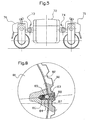
- the figure 5 shows a machine of this type comprising two relatively light body structures 70, 71 each equipped with a drum and its drive device and a central support at least partially shielded containing a hydraulic unit 72.
- the joints 73 and 74 are then arranged in the upper parts of the bodyshell structures 70, 71 and the armature of the hydraulic unit 72.
- the drive motors of the drums are supplied with hydraulic fluid under pressure from the central unit 72 via flexible tubes (not shown ).
- the two structures 7, 8 are connected to each other, on either side of the articulation 3, by two respective cylinders 28, 29, for example hydraulic, electric or pneumatic, intended to modify the position angular relative of the two parts, in order to allow the driving of the machine (straight line or bend).
- the drum consists of a multiplicity of steel D disks arranged side by side and each presenting, as illustrated in FIG. figure 6 a central cavity 30 having a triangular shape with concave curvilinear sides and curved angles.
- cavities 30 form a passage in which engages a shaft 31 whose section has a shape similar to that of the cavity 30, but on a reduced scale.
- the curved angular regions of this shaft 31 here consist of cylindrical rollers 32, 33, 34.
- the shaft 31 is fixed at each of its ends to a coaxial disc 36, 37 for lateral support of the floating discs D and a pinion 24, 25. Its rotatable mounting on the wings 17, 17 'is effected by means of bearings 38, 39 in which are engaged pins 40, 41 extending coaxially.
- each of the floating disks D carries at its periphery a toothed lining 42 formed by a succession of removable and interchangeable segments 43 fixed by screwing on the edge of the disk D.
- These segments 43 may be made of a resilient and resistant material such as a rubber or elastomer.
- the lining may be mounted on the disk by means of a load-breaking connection allowing a relative rotation of the lining with respect to the disk when the torque exerted between said lining and said disk amounts to beyond a predetermined threshold.
- the figure 8 shows a possible solution for the realization of such a load-breaking connection in which the lining consists of a ring 80 of diameter substantially equal to the diameter of the edge of the floating disk 81 on which it comes to engage coaxially.
- This cylindrical inner face of this ring 80 is provided with an annular groove 82 whose bottom is provided with at least three notches 83 (or notches). In this groove engages at least one ball 84 or the like partially housed in a blind housing 85 of cylindrical shape oriented radially, which is formed in the edge of the disk 81.
- This ball 84 is biased by a pressure spring 86 or Belleville type compression washers bearing in the bottom of the housing 85.
- the mounting of the ring 80 on the disk 81 is then made possible by radial threaded holes 87 opening to the right of the groove 82 and closed by a set screw 88.
- the balls 84 can be engaged in their respective housing 86 after having disposed the ring 80 on the disk 81.
- you want to remove the seal simply remove the balls 84 after removing the set screws 88.
- the notches in which engage the balls are made at the end of the set screws 88.
- the movements of the machine are ensured thanks to the rotational drive of the drums 13, 14 by means of the kinematic chain comprising the motors 22, 23, the pinions 20, 21 - 24, 25 , the drive chain 27 and the tripod shaft 31 which the rotation causes the rotation of the discs D while allowing their relative radial displacement.
- the machine could have a structure similar to that of a conventional public works machine comprising ( Figures 9 and 10 ) a rear portion 50 equipped with a driving cabin 51 and a front portion of the type described above, it being understood that, in this case, the cabin 51 is designed to protect the driver against blasts.
- the connection between the two parts is provided in the same way as before, by means of a double articulation 52 and one or more steering control cylinders 53, 54 which generates a torque between the two parts relative to the vertical hinge pin.
- the two running gear of this machine consist of drums 55, 56 similar to those used on the machine previously described.
- the two parts of the machine may be rigidly connected to one another so as to constitute a common structure as illustrated.
- Figures 11 and 12 one of the undercarriages, preferably the rear axle, is composed of steerable wheels 57, 58, of which the orientation is controlled by a steering wheel 59 located in a cabin 60 provided at the rear of the structure.
- the demining machines described above may be equipped with cameras 60 as well as the means necessary for transmitting images to the control screen located on board the craft (in the case where it is equipped with a cabin of piloting) or at a distance from the machine, especially in the case where the machine is remotely controlled.
- this camera 60 may be fixed or remotely controllable by the operator.
- demining machines may further comprise one or more detection devices such as magnetic means known for manual demining, or other detection means such as geophysical equipment such as for example conductivity meters, so that all unexploded ordnance is detected to be reported to demining personnel with a view to being neutralized manually.
- detection devices such as magnetic means known for manual demining, or other detection means such as geophysical equipment such as for example conductivity meters, so that all unexploded ordnance is detected to be reported to demining personnel with a view to being neutralized manually.
- drums may optionally comprise at least two sections each comprising a set of floating discs of the type described above arranged side by side and radially movable relative to each other.
- these two sections T 1 , T 2 are rotatably mounted about a fixed axis AF which passes through the orifices O, O 'disks D, D' to be fixed by its ends on the wings 17, 17 '.
- the rotational drive of the sections T 1 , T 2 is ensured by means of two sleeves M, M 'rotatably mounted about the axis AF and respectively coupled to the gears 24, 25.
- the outer shape of the sleeves M, M ' corresponds to that of the drive means described above.
Landscapes
- Engineering & Computer Science (AREA)
- Mechanical Engineering (AREA)
- Transportation (AREA)
- General Engineering & Computer Science (AREA)
- Fire-Extinguishing By Fire Departments, And Fire-Extinguishing Equipment And Control Thereof (AREA)
- Gear Transmission (AREA)
- User Interface Of Digital Computer (AREA)
- Manipulator (AREA)
- Aiming, Guidance, Guns With A Light Source, Armor, Camouflage, And Targets (AREA)
- Detergent Compositions (AREA)
Claims (26)
- Minenräumgerät, das, insbesondere, jedoch nicht ausschließlich, zur Zerstörung von Antipersonenminen, durch Auslösung ihres Zündsystems verwendbar ist, wobei dieses Gerät mindestens einen Rollengang umfasst, der mindestens eine Walze (13, 14) umfasst, die aus einer Gesamtheit von losen Scheiben (D), beispielsweise aus Stahl, besteht, die hintereinander im Wesentlichen koaxial angeordnet und gegenseitig radial beweglich sind,
dadurch gekennzeichnet, dass diese Scheiben (D) jeweils eine zentrale Öffnung (30) umfassen, durch die hindurch Drehantriebsmittel (31) verlaufen, die sich axial von einem Ende zum anderen Ende der Walze (13, 14) erstrecken und die mit einer Motorisierung gekoppelt sind, wobei diese Antriebsmittel (31) Anschlagflächen aufweisen, die mit Anschlagflächen kooperieren, die in den Scheiben (D) an den Öffnungen (30) vorgesehen sind, derart, dass die Mittel (31) den Drehantrieb von jeder der Scheiben (D) gewährleisten und ihnen dennoch ein radialer Freiheitsgrad bezüglich der Achse der Drehantriebsmittel (31) erlaubt ist. - Gerät nach Anspruch 1,
dadurch gekennzeichnet, dass die Öffnungen (30) der Scheiben (D) eine längliche Form oder eine polygonale Form mit gekrümmten Seiten aufweisen. - Gerät nach einem der Ansprüche 1 und 2,
dadurch gekennzeichnet, dass die oben genannten Öffnungen (30) die Form eines gekrümmten Dreiecks mit konkaven Seiten, deren Ecken abgerundet sind, aufweisen. - Gerät nach Anspruch 3,
dadurch gekennzeichnet, dass die Antriebsmittel (31) eine dreibeinige Welle mit, bezogen auf denjenigen der oben genannten Öffnungen (30), reduziertem Querschnitt aufweisen. - Gerät nach Anspruch 3,
dadurch gekennzeichnet, dass die Antriebsmittel (31) drei parallele Zylinder (32, 33, 34) umfassen, deren Achsen ein gleichschenkliges Prisma definieren. - Gerät nach Anspruch 5,
dadurch gekennzeichnet, dass die oben genannten Zylinder (32, 33, 34) mit ihren Enden an zwei koaxialen Scheiben (36, 37) befestigt sind, die dem seitlichen Halt der losen Scheiben (D) dienen. - Gerät nach einem der vorhergehenden Ansprüche,
dadurch gekennzeichnet, dass Zwischenbeläge, die aus korrosionsfreiem Material realisiert sind und die Antifriktionseigenschaften besitzen, mindestens eine Frontfläche von jeder Metallscheibe (D) bedecken oder überziehen, um das Aneinanderkleben der Scheiben zu verhindern. - Gerät nach einem der vorhergehenden Ansprüche,
dadurch gekennzeichnet, dass die losen Scheiben jeweils an ihrem Umfang einen gezahnten Beschlag (42) tragen, der von einer Abfolge von abnehmbaren und austauschbaren Segmenten (43) gebildet ist, die auf dem Rand der Scheibe (D) befestigt sind. - Gerät nach einem der Ansprüche 1 bis 7,
dadurch gekennzeichnet, dass der Belag (80) auf der Scheibe (81) über eine Belastungswechselverbindung befestigt ist, die eine relative Rotation des Belags (80) bezüglich der Scheibe (81) erlaubt, wenn das zwischen Belag (80) und Scheibe (81) ausgeübte Drehmoment über einen vorbestimmten Schwellwert ansteigt. - Gerät nach einem der vorhergehenden Ansprüche,
dadurch gekennzeichnet, dass die oben genannte Walze aus mehren Teilstücken (T1, T2) geformt ist, die jeweils eine Gesamtheit von losen Scheiben (D, D') tragen, die nebeneinander und untereinander radial beweglich angeordnet sind, wobei diese Scheiben (D, D') jeweils eine zentrale Öffnung (O, O') umfassen, durch die hindurch für jedes Teilstück (T1, T2) unabhängige Rotationsantriebmittel verlaufen. - Gerät nach einem der vorhergehenden Ansprüche,
dadurch gekennzeichnet, dass es mindestens zwei Rollengänge umfasst, nämlich vorne einem Gang, bestehend aus einer Walze des zuvor beschriebenen Typs, und hinten einen beliebigen Rollengang, der eine oder mehrere Walzen umfassen kann. - Gerät nach Anspruch 11,
dadurch gekennzeichnet, dass mindestens einer der Rollgänge Richtwirkung besitzt und mit dem anderen über mindestens eine Gelenkverbindung (5) mit vertikaler Achse zusammenhängt. - Gerät nach Anspruch 12,
dadurch gekennzeichnet, dass die oben genannte Gelenkverbindung weiterhin eine Traglagereinheit (4) mit Längsachse umfasst. - Gerät nach einem der vorhergehenden Ansprüche,
dadurch gekennzeichnet, dass es eine Motorisierung umfasst, umfassend einen oder mehrere Motoren (22, 23) in Kontakt mit den oben genannten Antriebsmitteln (31), entweder direkt oder über eine Übersetzung durch Ketten. - Gerät nach einem der vorhergehenden Ansprüche,
dadurch gekennzeichnet, dass es zwei Teile (1, 2) umfasst, die jeweils einen Rollengang umfassen, wovon der eine mindestens aus einer Walze (13, 14) des oben genannten Typs besteht, wobei diese beiden Teile (1, 2) über eine Gelenkverbindung (3) miteinander verbunden sind, die mindestens eine Traglagereinheit mit vertikaler Achse umfasst. - Gerät nach Anspruch 15,
dadurch gekennzeichnet, dass die oben genannte Gelenkverbindung weiterhin eine Traglagereinheit mit Längsachsen (X, X') umfasst. - Gerät nach einem der Ansprüche 15 und 16,
dadurch gekennzeichnet, dass es mindestens ein Stellglied (28, 29) umfasst, das zwischen den beiden Teilen (1, 2) ein Drehmoment bezüglich der vertikalen Rotationsachse (Y, Y') erzeugt. - Gerät nach einem der Ansprüche 1 bis 14,
dadurch gekennzeichnet, dass es eine gemeinsame Struktur umfasst, die mit zwei Rollgängen versehen ist, wobei einer der beiden Gänge, vorzugsweise der vordere Gang, die oben genannte Walze umfasst, und der zweite Gang, vorzugsweise der hintere Gang, steuerbare Orientierungsräder (57, 58) umfasst. - Gerät nach Anspruch 18,
dadurch gekennzeichnet, dass der zweite Gang eine Lotsenkabine umfasst, die mit einem Steuerrad (59) ausgestattet ist, das dazu dient, die Orientierung der oben genannten Räder (57, 58) zu steuern. - Gerät nach einem der Ansprüche 1 bis 14,
dadurch gekennzeichnet, dass es zwei Teile (70, 71) umfasst, die jeweils einen Rollengang umfassen, der mindestens eine Walze des oben genannten Typs umfasst, wobei diese beiden Teile (70, 71) mit einem Mittelteil (72), das eine Hydraulikeinheit umfasst, gelenkig verbunden sind. - Gerät nach einem der Ansprüche 1 bis 18,
dadurch gekennzeichnet, dass es Mittel zur Fernsteuerung über Kabelverbindung oder Funkverbindung umfasst. - Gerät nach einem der vorhergehenden Ansprüche,
dadurch gekennzeichnet, dass es mindestens eine Kamera (60) sowie Mittel umfasst, die notwendig sind, um Bilder auf den Lotsenbildschirm, der an Bord des Geräts angeordneten ist, in dem Fall zu übertragen, wobei es mit einer Lotsenkabine ausgestattet ist, oder in Entfernung von dem Gerät zu übertragen, insbesondere in dem Fall, wobei das Gerät ferngesteuert ist. - Gerät nach einem Anspruch 22,
dadurch gekennzeichnet, dass die oben genannte Kamera (60) feststehend ist oder zur fernsteuerbaren Orientierung ist. - Gerät nach einem der vorhergehenden Ansprüche,
dadurch gekennzeichnet, dass es eine oder mehrere Detektions-Vorrichtungen umfasst, wie magnetische Mittel, für manuelles Entminen die bekannt sind, oder andere Detektions-Vorrichtungen, wie geophysikalische Materialien, wie zum Beispiel Leitfähigkeitsmesser, derart, dass jedes nicht detonierte Gerät detektiert wird, damit dem Entminungspersonal im Hinblick auf manuelle Neutralisation ein Signal gegeben wird. - Gerät nach einem der vorhergehenden Ansprüche,
dadurch gekennzeichnet, dass es Mittel zur Markierung der Durchgangszonen des Geräts umfasst, zum Beispiel durch Ausstreuen einer sichtbaren Substanz, wie Kreide oder Kalk oder ein Farbstoff. - Gerät nach einem der vorhergehenden Ansprüche,
dadurch gekennzeichnet, dass es ein Programmiersystem der Trajektorien umfasst, das in das fahrzeugseitige System eingebaut ist, um die Auslenkungen des Geräts in einem Raum unter Garantie, dass es über jeden Punkt von diesem fährt, zu steuern.
Applications Claiming Priority (2)
| Application Number | Priority Date | Filing Date | Title |
|---|---|---|---|
| FR0701511A FR2913264B1 (fr) | 2007-03-01 | 2007-03-01 | Engin de deminage notamment pour mines antipersonnel. |
| PCT/FR2008/000242 WO2008125756A2 (fr) | 2007-03-01 | 2008-02-22 | Engin de deminage notamment pour mines antipersonnel |
Publications (2)
| Publication Number | Publication Date |
|---|---|
| EP2118616A2 EP2118616A2 (de) | 2009-11-18 |
| EP2118616B1 true EP2118616B1 (de) | 2010-06-09 |
Family
ID=38623970
Family Applications (1)
| Application Number | Title | Priority Date | Filing Date |
|---|---|---|---|
| EP08775593A Not-in-force EP2118616B1 (de) | 2007-03-01 | 2008-02-22 | Insbesondere für anti-personen-minen konzipiertes minenräumungsfahrzeug |
Country Status (5)
| Country | Link |
|---|---|
| EP (1) | EP2118616B1 (de) |
| AT (1) | ATE470833T1 (de) |
| DE (1) | DE602008001501D1 (de) |
| FR (1) | FR2913264B1 (de) |
| WO (1) | WO2008125756A2 (de) |
Cited By (6)
| Publication number | Priority date | Publication date | Assignee | Title |
|---|---|---|---|---|
| US10670479B2 (en) | 2018-02-27 | 2020-06-02 | Methode Electronics, Inc. | Towing systems and methods using magnetic field sensing |
| US10696109B2 (en) | 2017-03-22 | 2020-06-30 | Methode Electronics Malta Ltd. | Magnetolastic based sensor assembly |
| US11084342B2 (en) | 2018-02-27 | 2021-08-10 | Methode Electronics, Inc. | Towing systems and methods using magnetic field sensing |
| US11135882B2 (en) | 2018-02-27 | 2021-10-05 | Methode Electronics, Inc. | Towing systems and methods using magnetic field sensing |
| US11221262B2 (en) | 2018-02-27 | 2022-01-11 | Methode Electronics, Inc. | Towing systems and methods using magnetic field sensing |
| US11491832B2 (en) | 2018-02-27 | 2022-11-08 | Methode Electronics, Inc. | Towing systems and methods using magnetic field sensing |
Families Citing this family (1)
| Publication number | Priority date | Publication date | Assignee | Title |
|---|---|---|---|---|
| RU2497155C1 (ru) * | 2012-06-07 | 2013-10-27 | Григорий Николаевич Щербаков | Способ и устройство обнаружения противопехотных взрывных устройств с контактно-проводными датчиками цели |
Family Cites Families (4)
| Publication number | Priority date | Publication date | Assignee | Title |
|---|---|---|---|---|
| BE459207A (de) * | ||||
| GB2294910B (en) * | 1994-11-10 | 1998-08-12 | Robert Henry Booth | Apparatus for use in clearing land mines |
| JP2862861B1 (ja) * | 1998-02-02 | 1999-03-03 | 正則 高杉 | 地雷処理ロボット |
| FR2851036B1 (fr) * | 2003-02-06 | 2007-06-08 | Gregoire Guitre | Dispositif de deminage pour des mines anti-personnel dans des zones d'acces difficile |
-
2007
- 2007-03-01 FR FR0701511A patent/FR2913264B1/fr not_active Expired - Fee Related
-
2008
- 2008-02-22 EP EP08775593A patent/EP2118616B1/de not_active Not-in-force
- 2008-02-22 WO PCT/FR2008/000242 patent/WO2008125756A2/fr not_active Ceased
- 2008-02-22 DE DE602008001501T patent/DE602008001501D1/de active Active
- 2008-02-22 AT AT08775593T patent/ATE470833T1/de not_active IP Right Cessation
Cited By (7)
| Publication number | Priority date | Publication date | Assignee | Title |
|---|---|---|---|---|
| US10696109B2 (en) | 2017-03-22 | 2020-06-30 | Methode Electronics Malta Ltd. | Magnetolastic based sensor assembly |
| US10940726B2 (en) | 2017-03-22 | 2021-03-09 | Methode Electronics Malta Ltd. | Magnetoelastic based sensor assembly |
| US10670479B2 (en) | 2018-02-27 | 2020-06-02 | Methode Electronics, Inc. | Towing systems and methods using magnetic field sensing |
| US11084342B2 (en) | 2018-02-27 | 2021-08-10 | Methode Electronics, Inc. | Towing systems and methods using magnetic field sensing |
| US11135882B2 (en) | 2018-02-27 | 2021-10-05 | Methode Electronics, Inc. | Towing systems and methods using magnetic field sensing |
| US11221262B2 (en) | 2018-02-27 | 2022-01-11 | Methode Electronics, Inc. | Towing systems and methods using magnetic field sensing |
| US11491832B2 (en) | 2018-02-27 | 2022-11-08 | Methode Electronics, Inc. | Towing systems and methods using magnetic field sensing |
Also Published As
| Publication number | Publication date |
|---|---|
| FR2913264A1 (fr) | 2008-09-05 |
| WO2008125756A2 (fr) | 2008-10-23 |
| ATE470833T1 (de) | 2010-06-15 |
| DE602008001501D1 (de) | 2010-07-22 |
| EP2118616A2 (de) | 2009-11-18 |
| WO2008125756A3 (fr) | 2008-12-11 |
| FR2913264B1 (fr) | 2009-05-01 |
Similar Documents
| Publication | Publication Date | Title |
|---|---|---|
| WO2008125756A2 (fr) | Engin de deminage notamment pour mines antipersonnel | |
| EP2543592B1 (de) | Elektrisches Motorisierungssystem eines Rads | |
| FR2564053A1 (fr) | Chassis a suspension a bras tires | |
| CA1177010A (fr) | Engin transporteur-tracteur aerien automoteur automatique se deplacant sur un cable porteur | |
| CA2744969C (fr) | Materiel roulant pour declencher des charges explosives et ensemble motorise pour securiser des routes, pistes ou analogues | |
| FR2939764A1 (fr) | Train d'atterrissage d'aeronef avec motorisation et transmission | |
| EP3541689B1 (de) | Laufwerk für ein raupenfahrzeug, raupenfahrzeug mit solch einem laufwerk und verfahren zur umwandlung eines radfahrzeugs in ein raupenfahrzeug | |
| EP2858884B1 (de) | Rollender roboter mit rädern | |
| WO2015135986A1 (fr) | Vehicule a grande capacite de franchissement | |
| FR2987804A1 (fr) | Carenage de roue ou de bande de roulement d'un engin roulant presentant un element aerodyamique et/ou de protection de la roue ou bande de roulement ainsi qu'engin roulant dote d'au moins un tel carenage | |
| EP3226389A1 (de) | Motor eines schienenfahrzeugs, und verfahren zur montage eines motors | |
| EP2397808B1 (de) | Vorrichtung zur Neutralisierung eine mit einem Draht gesteuerte Sprengladung oder dergleichen | |
| FR2663727A1 (fr) | Structure composite pour le tir au mortier a partir d'un engin motorise. | |
| FR2534213A1 (fr) | Tracteur ou vehicule similaire muni de roues motrices et directrices commandees par des fusees | |
| EP2299233A1 (de) | Selbststeuernde motorisierte Gelenk-Kombination | |
| EP4255793B1 (de) | Verfahren und system zur neutralisierung von aufsteigenden ruckbewegungen mit unterstützung durch eine fahrzeuglenksäule | |
| FR2701429A1 (fr) | Dispositif de roue et véhicule auto-moteur comportant un tel dispositif. | |
| FR2851036A1 (fr) | Dispositif de deminage pour des mines anti-personnel dans des zones d'acces difficile | |
| BE478958A (de) | ||
| FR3155802A1 (fr) | Essieu pendulaire pour véhicule de type tricycle | |
| WO2024133155A1 (fr) | Dispositif apte à se déplacer sur des terrains difficiles, tels qu'un champ de mines, ou sur des terrains sensibles, tels que des champs agricoles | |
| WO2013127932A1 (fr) | Véhicule de déminage léger | |
| FR3138354A1 (fr) | Kit rail motorisé | |
| BE414564A (de) | ||
| FR2550493A1 (fr) | Perfectionnements aux roues a rayons elastiques en vue d'accroitre l'adherence d'un vehicule sur tous terrains |
Legal Events
| Date | Code | Title | Description |
|---|---|---|---|
| PUAI | Public reference made under article 153(3) epc to a published international application that has entered the european phase |
Free format text: ORIGINAL CODE: 0009012 |
|
| 17P | Request for examination filed |
Effective date: 20090917 |
|
| AK | Designated contracting states |
Kind code of ref document: A2 Designated state(s): AT BE BG CH CY CZ DE DK EE ES FI FR GB GR HR HU IE IS IT LI LT LU LV MC MT NL NO PL PT RO SE SI SK TR |
|
| GRAP | Despatch of communication of intention to grant a patent |
Free format text: ORIGINAL CODE: EPIDOSNIGR1 |
|
| GRAS | Grant fee paid |
Free format text: ORIGINAL CODE: EPIDOSNIGR3 |
|
| GRAA | (expected) grant |
Free format text: ORIGINAL CODE: 0009210 |
|
| DAX | Request for extension of the european patent (deleted) | ||
| AK | Designated contracting states |
Kind code of ref document: B1 Designated state(s): AT BE BG CH CY CZ DE DK EE ES FI FR GB GR HR HU IE IS IT LI LT LU LV MC MT NL NO PL PT RO SE SI SK TR |
|
| REG | Reference to a national code |
Ref country code: CH Ref legal event code: EP |
|
| REG | Reference to a national code |
Ref country code: IE Ref legal event code: FG4D Free format text: LANGUAGE OF EP DOCUMENT: FRENCH |
|
| REF | Corresponds to: |
Ref document number: 602008001501 Country of ref document: DE Date of ref document: 20100722 Kind code of ref document: P |
|
| REG | Reference to a national code |
Ref country code: CH Ref legal event code: NV Representative=s name: CABINET MOUTARD |
|
| REG | Reference to a national code |
Ref country code: NL Ref legal event code: VDEP Effective date: 20100609 |
|
| PG25 | Lapsed in a contracting state [announced via postgrant information from national office to epo] |
Ref country code: LT Free format text: LAPSE BECAUSE OF FAILURE TO SUBMIT A TRANSLATION OF THE DESCRIPTION OR TO PAY THE FEE WITHIN THE PRESCRIBED TIME-LIMIT Effective date: 20100609 Ref country code: NO Free format text: LAPSE BECAUSE OF FAILURE TO SUBMIT A TRANSLATION OF THE DESCRIPTION OR TO PAY THE FEE WITHIN THE PRESCRIBED TIME-LIMIT Effective date: 20100909 Ref country code: SE Free format text: LAPSE BECAUSE OF FAILURE TO SUBMIT A TRANSLATION OF THE DESCRIPTION OR TO PAY THE FEE WITHIN THE PRESCRIBED TIME-LIMIT Effective date: 20100609 |
|
| LTIE | Lt: invalidation of european patent or patent extension |
Effective date: 20100609 |
|
| PG25 | Lapsed in a contracting state [announced via postgrant information from national office to epo] |
Ref country code: FI Free format text: LAPSE BECAUSE OF FAILURE TO SUBMIT A TRANSLATION OF THE DESCRIPTION OR TO PAY THE FEE WITHIN THE PRESCRIBED TIME-LIMIT Effective date: 20100609 Ref country code: AT Free format text: LAPSE BECAUSE OF FAILURE TO SUBMIT A TRANSLATION OF THE DESCRIPTION OR TO PAY THE FEE WITHIN THE PRESCRIBED TIME-LIMIT Effective date: 20100609 Ref country code: HR Free format text: LAPSE BECAUSE OF FAILURE TO SUBMIT A TRANSLATION OF THE DESCRIPTION OR TO PAY THE FEE WITHIN THE PRESCRIBED TIME-LIMIT Effective date: 20100609 Ref country code: LV Free format text: LAPSE BECAUSE OF FAILURE TO SUBMIT A TRANSLATION OF THE DESCRIPTION OR TO PAY THE FEE WITHIN THE PRESCRIBED TIME-LIMIT Effective date: 20100609 Ref country code: SI Free format text: LAPSE BECAUSE OF FAILURE TO SUBMIT A TRANSLATION OF THE DESCRIPTION OR TO PAY THE FEE WITHIN THE PRESCRIBED TIME-LIMIT Effective date: 20100609 |
|
| PG25 | Lapsed in a contracting state [announced via postgrant information from national office to epo] |
Ref country code: PL Free format text: LAPSE BECAUSE OF FAILURE TO SUBMIT A TRANSLATION OF THE DESCRIPTION OR TO PAY THE FEE WITHIN THE PRESCRIBED TIME-LIMIT Effective date: 20100609 Ref country code: CY Free format text: LAPSE BECAUSE OF FAILURE TO SUBMIT A TRANSLATION OF THE DESCRIPTION OR TO PAY THE FEE WITHIN THE PRESCRIBED TIME-LIMIT Effective date: 20100616 |
|
| REG | Reference to a national code |
Ref country code: IE Ref legal event code: FD4D |
|
| PG25 | Lapsed in a contracting state [announced via postgrant information from national office to epo] |
Ref country code: EE Free format text: LAPSE BECAUSE OF FAILURE TO SUBMIT A TRANSLATION OF THE DESCRIPTION OR TO PAY THE FEE WITHIN THE PRESCRIBED TIME-LIMIT Effective date: 20100609 Ref country code: IE Free format text: LAPSE BECAUSE OF FAILURE TO SUBMIT A TRANSLATION OF THE DESCRIPTION OR TO PAY THE FEE WITHIN THE PRESCRIBED TIME-LIMIT Effective date: 20100609 Ref country code: NL Free format text: LAPSE BECAUSE OF FAILURE TO SUBMIT A TRANSLATION OF THE DESCRIPTION OR TO PAY THE FEE WITHIN THE PRESCRIBED TIME-LIMIT Effective date: 20100609 |
|
| PG25 | Lapsed in a contracting state [announced via postgrant information from national office to epo] |
Ref country code: SK Free format text: LAPSE BECAUSE OF FAILURE TO SUBMIT A TRANSLATION OF THE DESCRIPTION OR TO PAY THE FEE WITHIN THE PRESCRIBED TIME-LIMIT Effective date: 20100609 Ref country code: CZ Free format text: LAPSE BECAUSE OF FAILURE TO SUBMIT A TRANSLATION OF THE DESCRIPTION OR TO PAY THE FEE WITHIN THE PRESCRIBED TIME-LIMIT Effective date: 20100609 Ref country code: IS Free format text: LAPSE BECAUSE OF FAILURE TO SUBMIT A TRANSLATION OF THE DESCRIPTION OR TO PAY THE FEE WITHIN THE PRESCRIBED TIME-LIMIT Effective date: 20101009 Ref country code: RO Free format text: LAPSE BECAUSE OF FAILURE TO SUBMIT A TRANSLATION OF THE DESCRIPTION OR TO PAY THE FEE WITHIN THE PRESCRIBED TIME-LIMIT Effective date: 20100609 |
|
| PG25 | Lapsed in a contracting state [announced via postgrant information from national office to epo] |
Ref country code: IT Free format text: LAPSE BECAUSE OF FAILURE TO SUBMIT A TRANSLATION OF THE DESCRIPTION OR TO PAY THE FEE WITHIN THE PRESCRIBED TIME-LIMIT Effective date: 20100609 |
|
| PLBE | No opposition filed within time limit |
Free format text: ORIGINAL CODE: 0009261 |
|
| STAA | Information on the status of an ep patent application or granted ep patent |
Free format text: STATUS: NO OPPOSITION FILED WITHIN TIME LIMIT |
|
| PG25 | Lapsed in a contracting state [announced via postgrant information from national office to epo] |
Ref country code: DK Free format text: LAPSE BECAUSE OF FAILURE TO SUBMIT A TRANSLATION OF THE DESCRIPTION OR TO PAY THE FEE WITHIN THE PRESCRIBED TIME-LIMIT Effective date: 20100609 |
|
| PG25 | Lapsed in a contracting state [announced via postgrant information from national office to epo] |
Ref country code: GR Free format text: LAPSE BECAUSE OF FAILURE TO SUBMIT A TRANSLATION OF THE DESCRIPTION OR TO PAY THE FEE WITHIN THE PRESCRIBED TIME-LIMIT Effective date: 20100910 |
|
| REG | Reference to a national code |
Ref country code: DE Ref legal event code: R097 Ref document number: 602008001501 Country of ref document: DE Effective date: 20110309 |
|
| PG25 | Lapsed in a contracting state [announced via postgrant information from national office to epo] |
Ref country code: MC Free format text: LAPSE BECAUSE OF NON-PAYMENT OF DUE FEES Effective date: 20110228 |
|
| PG25 | Lapsed in a contracting state [announced via postgrant information from national office to epo] |
Ref country code: MT Free format text: LAPSE BECAUSE OF FAILURE TO SUBMIT A TRANSLATION OF THE DESCRIPTION OR TO PAY THE FEE WITHIN THE PRESCRIBED TIME-LIMIT Effective date: 20100609 |
|
| REG | Reference to a national code |
Ref country code: CH Ref legal event code: PFA Owner name: HOVAGUIMIAN, ROUBEN Free format text: HOVAGUIMIAN, ROUBEN# #27 RUE DU 14 JUILLET 94140 ALFORVILLE (FR) $ HANS, ANDRE# #5 IMPASSE BERENICE 78180 MONTIGNY LE BRETONNEUX (FR) -TRANSFER TO- HOVAGUIMIAN, ROUBEN# #27 RUE DU 14 JUILLET 94140 ALFORVILLE (FR) $ HANS, ANDRE# #5 IMPASSE BERENICE 78180 MONTIGNY LE BRETONNEUX (FR) |
|
| REG | Reference to a national code |
Ref country code: CH Ref legal event code: PCAR Free format text: NEW ADDRESS: RUE DE LYON 75 - 4EME ETAGE, 1203 GENEVE (CH) |
|
| PG25 | Lapsed in a contracting state [announced via postgrant information from national office to epo] |
Ref country code: LU Free format text: LAPSE BECAUSE OF NON-PAYMENT OF DUE FEES Effective date: 20110222 |
|
| PG25 | Lapsed in a contracting state [announced via postgrant information from national office to epo] |
Ref country code: PT Free format text: LAPSE BECAUSE OF NON-PAYMENT OF DUE FEES Effective date: 20100609 |
|
| PG25 | Lapsed in a contracting state [announced via postgrant information from national office to epo] |
Ref country code: TR Free format text: LAPSE BECAUSE OF FAILURE TO SUBMIT A TRANSLATION OF THE DESCRIPTION OR TO PAY THE FEE WITHIN THE PRESCRIBED TIME-LIMIT Effective date: 20100609 Ref country code: BG Free format text: LAPSE BECAUSE OF FAILURE TO SUBMIT A TRANSLATION OF THE DESCRIPTION OR TO PAY THE FEE WITHIN THE PRESCRIBED TIME-LIMIT Effective date: 20100909 |
|
| PG25 | Lapsed in a contracting state [announced via postgrant information from national office to epo] |
Ref country code: HU Free format text: LAPSE BECAUSE OF FAILURE TO SUBMIT A TRANSLATION OF THE DESCRIPTION OR TO PAY THE FEE WITHIN THE PRESCRIBED TIME-LIMIT Effective date: 20100609 Ref country code: ES Free format text: LAPSE BECAUSE OF FAILURE TO SUBMIT A TRANSLATION OF THE DESCRIPTION OR TO PAY THE FEE WITHIN THE PRESCRIBED TIME-LIMIT Effective date: 20100920 |
|
| REG | Reference to a national code |
Ref country code: FR Ref legal event code: PLFP Year of fee payment: 8 |
|
| PGFP | Annual fee paid to national office [announced via postgrant information from national office to epo] |
Ref country code: CH Payment date: 20150213 Year of fee payment: 8 |
|
| PGFP | Annual fee paid to national office [announced via postgrant information from national office to epo] |
Ref country code: GB Payment date: 20150216 Year of fee payment: 8 Ref country code: FR Payment date: 20150121 Year of fee payment: 8 |
|
| PGFP | Annual fee paid to national office [announced via postgrant information from national office to epo] |
Ref country code: BE Payment date: 20150123 Year of fee payment: 8 |
|
| PGFP | Annual fee paid to national office [announced via postgrant information from national office to epo] |
Ref country code: DE Payment date: 20150423 Year of fee payment: 8 |
|
| PG25 | Lapsed in a contracting state [announced via postgrant information from national office to epo] |
Ref country code: BE Free format text: LAPSE BECAUSE OF NON-PAYMENT OF DUE FEES Effective date: 20160229 |
|
| REG | Reference to a national code |
Ref country code: DE Ref legal event code: R119 Ref document number: 602008001501 Country of ref document: DE |
|
| REG | Reference to a national code |
Ref country code: CH Ref legal event code: PL |
|
| GBPC | Gb: european patent ceased through non-payment of renewal fee |
Effective date: 20160222 |
|
| PG25 | Lapsed in a contracting state [announced via postgrant information from national office to epo] |
Ref country code: CH Free format text: LAPSE BECAUSE OF NON-PAYMENT OF DUE FEES Effective date: 20160229 Ref country code: LI Free format text: LAPSE BECAUSE OF NON-PAYMENT OF DUE FEES Effective date: 20160229 |
|
| REG | Reference to a national code |
Ref country code: FR Ref legal event code: ST Effective date: 20161028 |
|
| PG25 | Lapsed in a contracting state [announced via postgrant information from national office to epo] |
Ref country code: GB Free format text: LAPSE BECAUSE OF NON-PAYMENT OF DUE FEES Effective date: 20160222 Ref country code: FR Free format text: LAPSE BECAUSE OF NON-PAYMENT OF DUE FEES Effective date: 20160229 Ref country code: DE Free format text: LAPSE BECAUSE OF NON-PAYMENT OF DUE FEES Effective date: 20160901 |