EP2119028B1 - Adaptive echounterdrückung für einen hf-gleichfrequenzverstärker mit gewichtetem leistungsspektrum - Google Patents
Adaptive echounterdrückung für einen hf-gleichfrequenzverstärker mit gewichtetem leistungsspektrum Download PDFInfo
- Publication number
- EP2119028B1 EP2119028B1 EP08713187.6A EP08713187A EP2119028B1 EP 2119028 B1 EP2119028 B1 EP 2119028B1 EP 08713187 A EP08713187 A EP 08713187A EP 2119028 B1 EP2119028 B1 EP 2119028B1
- Authority
- EP
- European Patent Office
- Prior art keywords
- signal
- echo
- power spectrum
- repeater
- power
- Prior art date
- Legal status (The legal status is an assumption and is not a legal conclusion. Google has not performed a legal analysis and makes no representation as to the accuracy of the status listed.)
- Active
Links
- 238000001228 spectrum Methods 0.000 title claims description 75
- 230000003044 adaptive effect Effects 0.000 title claims description 4
- 238000000034 method Methods 0.000 claims description 27
- 230000003595 spectral effect Effects 0.000 claims description 18
- 239000000969 carrier Substances 0.000 claims description 7
- 238000001914 filtration Methods 0.000 claims description 5
- 230000000694 effects Effects 0.000 claims description 3
- 238000004891 communication Methods 0.000 claims description 2
- 238000000638 solvent extraction Methods 0.000 claims 1
- 230000008878 coupling Effects 0.000 description 15
- 238000010168 coupling process Methods 0.000 description 15
- 238000005859 coupling reaction Methods 0.000 description 15
- 238000013139 quantization Methods 0.000 description 14
- 238000005259 measurement Methods 0.000 description 9
- 230000001934 delay Effects 0.000 description 8
- 230000007704 transition Effects 0.000 description 6
- 238000002592 echocardiography Methods 0.000 description 5
- 238000013459 approach Methods 0.000 description 4
- 238000010606 normalization Methods 0.000 description 4
- 230000008569 process Effects 0.000 description 4
- 230000002087 whitening effect Effects 0.000 description 4
- 230000001413 cellular effect Effects 0.000 description 3
- 238000010586 diagram Methods 0.000 description 3
- 239000011159 matrix material Substances 0.000 description 3
- 230000004044 response Effects 0.000 description 3
- 238000004364 calculation method Methods 0.000 description 2
- 238000010276 construction Methods 0.000 description 2
- 230000008859 change Effects 0.000 description 1
- 230000001419 dependent effect Effects 0.000 description 1
- 238000001514 detection method Methods 0.000 description 1
- 238000005562 fading Methods 0.000 description 1
- 230000002349 favourable effect Effects 0.000 description 1
- 238000013467 fragmentation Methods 0.000 description 1
- 238000006062 fragmentation reaction Methods 0.000 description 1
- 230000010354 integration Effects 0.000 description 1
- 230000000873 masking effect Effects 0.000 description 1
- 238000012986 modification Methods 0.000 description 1
- 230000004048 modification Effects 0.000 description 1
- 238000005192 partition Methods 0.000 description 1
- 230000009467 reduction Effects 0.000 description 1
- 238000007670 refining Methods 0.000 description 1
- 238000012546 transfer Methods 0.000 description 1
Images



Classifications
-
- H—ELECTRICITY
- H04—ELECTRIC COMMUNICATION TECHNIQUE
- H04B—TRANSMISSION
- H04B7/00—Radio transmission systems, i.e. using radiation field
- H04B7/14—Relay systems
- H04B7/15—Active relay systems
- H04B7/155—Ground-based stations
- H04B7/15564—Relay station antennae loop interference reduction
-
- H—ELECTRICITY
- H04—ELECTRIC COMMUNICATION TECHNIQUE
- H04B—TRANSMISSION
- H04B7/00—Radio transmission systems, i.e. using radiation field
- H04B7/24—Radio transmission systems, i.e. using radiation field for communication between two or more posts
- H04B7/26—Radio transmission systems, i.e. using radiation field for communication between two or more posts at least one of which is mobile
- H04B7/2603—Arrangements for wireless physical layer control
- H04B7/2606—Arrangements for base station coverage control, e.g. by using relays in tunnels
Definitions
- a mobile unit such as a cellular phone transmits and receives RF signals to and from cell site base stations.
- An on-frequency RF repeater receives, filters, and re-transmits the signal of interest at the same frequency and at a higher power level. If the product of the forward gain of the repeater and the coupling between antennas is too high, the repeater will oscillate. In general, this is undesirable.
- An internal feedback path may be used to compensate for the external coupling between antennas, allowing the forward gain of the repeater to be increased if required. This compensation is referred to as "echo cancellation.”
- Embodiments of the invention provide an adaptive echo cancellation system and method for an on-frequency RF repeater using a weighted power spectrum.
- the repeater preferably has a digital intermediate frequency (IF) stage, and internal digital echo cancellation is performed in a digital signal processor (DSP).
- DSP digital signal processor
- a preferred technique is based on the autocorrelation of the repeater signal (input signal plus echoes).
- the gain of the repeater is adjusted outside of the internal digital feedback loop of the echo cancellation, such as within the RF stages at the output side of the repeater.
- the RF gain of the repeater is set low initially, then increased to a maximum gain, so that the echo cancellation can adapt incrementally and maintain stability throughout.
- the autocorrelation detects echoes reliably when the width of the autocorrelation of the input signal is less than the loop delay of the echo path.
- Narrow bandwidth signals such as Enhanced Data rates for GSM Evolution (EDGE) can cause problems because the autocorrelations of the input signal and echo overlap.
- the repeater signal is filtered to reduce the width of the autocorrelation.
- the filter is designed to adjust the power of all carriers within the input signal so that each carrier has the same power density (on average) without affecting the ripples within the power spectrum that are needed to detect the echoes. When only one carrier is available, its power density is reduced to match the ambient noise of the repeater.
- the filtering is applied in the frequency domain to the power spectrum.
- This weighted power spectrum is Fourier transformed to produce a more favorable autocorrelation.
- Applying the filter to the power spectrum directly simplifies the computation of the optimum filter.
- the power spectrum is partitioned into disjoint bands by grouping frequency bins into a contiguous bands based on the measured power density. Each contiguous band approximates a carrier bandwidth or the guard region separating carriers.
- the power of each band is normalized so that the power spectral density equals a reference level.
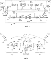
- FIG. 1 shows the block diagram of an on-frequency repeater 10 with a digital IF stage employing improved echo cancellation in accordance with a preferred embodiment of the invention.
- the repeater 10 is bi-directional, and may use a frequency division duplex (FDD) implementation to separate the up- and down-link paths 10a and 10b connecting the base station 100 and mobile user 110.
- the down-link 10a connects the base station 100 to the mobile 110
- the up-link 10b connects the mobile 110 to the base station 100.
- FDD frequency division duplex
- each path shown in an exemplary path in FIG. 2 with reference also to components in FIG. 1 , include the input (local area) antenna 12 (closest to the mobile 110), low noise amplifier (LNA) 23, down-converting mixer 24, IF filter 25, analog-to-digital converter (ADC) 26, digital signal processor (DSP) 15a or 15b ( FIG. 1 ), digital-to-analog converter (DAC) 27, up-converting mixer 28, power amplifier (PA) 29, and output (donor) antenna 13.
- ADC analog-to-digital converter
- DSP digital signal processor
- DAC digital-to-analog converter
- PA power amplifier
- additional components may be included in the repeater 10.
- first and second image reject filters may be included and located, e.g., between the LNA 23 and the down-converting mixer 24, and between the up-converting mixer 28 and the power amplifier 29, respectively.
- a first duplexer 11a may be provided between the antenna 12 and LNA 23.
- a circulator and a second duplexer 11b may be located, for example, between the PA 29 and the output antenna 13. Additional gain stages maybe present at various locations within the RF path 280 or the IF path 240 ( FIG. 2 ).
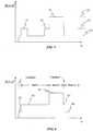
- the block diagram shown in FIG. 2 provides more details of the feedback paths within the individual links, 10a or 10b. It also shows the RF coupling H between the input antenna 12 and the output antenna 13.
- the echo cancellation is implemented using feedback compensation in a DSP (as shown in FIG. 1 ).
- the DSP-based compensation is converted to analog, and possibly up-converted in frequency, then coupled to the IF or RF path.
- the image reject filters, circulators, and duplexers are shown in FIG. 1 .
- the input signal e.g., the in-coming signal without the effects of feedback
- x(t) It's Fourier transform
- X( ⁇ ) The output signal and it's Fourier transform
- y(t) and Y( ⁇ ) respectively.
- the forward gain of the repeater 10 is represented as the product of the three gain blocks: an input gain G in , a digital gain G digital , and an output gain G out .
- G 0 G in G out .
- the product of the estimate feedback coupling block 151, the estimate of analog forward gain G 0 block 152, and the digital gain block 153 are generally referred to as the feedback path or feedback loop 150.
- the input signal X( ⁇ ) although used in the following for modeling, usually cannot be directly measured because it is difficult to separate X( ⁇ ) from the output signal Y( ⁇ ) through the coupling path H. What can be measured usually is a signal v(t) within a signal path of the repeater, measured prior to the digital gain G digital block 153.
- the IF filter 25 shown in FIG. 2 is modeled as a delay element within the repeater. This approximation assumes that the passband of the IF filter 25 is flat and that its bandwidth is wider than the spectrum of the input signal of interest. If this assumption is not valid, the estimated feedback coupling, H est , will be the product of the actual coupling, H, and the frequency response of the filter. This does not affect the approach to echo compensation; however, changes in the frequency response or gain of the filter will require re-estimation of the coefficients modeling the product of the feedback coupling and IF filter.
- G 0 G in G out .
- the input signal X( ⁇ ) is usually not available for measurement because the input antenna 12 sums both X( ⁇ ) and the coupled signal from the output antenna 13, ( H*Y ).
- Statistical properties of the measured signal, v(t) may be used to estimate the feedback coupling.
- the power spectrum of v(t) is used in the estimation and subsequent iterative search for the optimum feedback cancellation coefficients, b n .
- the autocorrelation of v(t) is denoted by ⁇ v ( ⁇ ), and can be computed from the power spectral density, (Eq. 4).
- T min When the minimum loop delay, T min , is greater than T a , the portion of the autocorrelation associated with the input signal and echo can be separated. In such cases, the autocorrelation is used to refine the feedback coefficient estimates associated with the dominant loop delays. For a repeater with a digital IF stage, it is easy to ensure that the minimum loop delay exceeds T a , although excessively large delays (>10 ⁇ s) are discouraged for cellular systems.
- the autocorrelation of the input signal denoted by E[x(t + ⁇ )x*(t)] where E[ ] indicates expected value, is zero for r > T min
- the estimate of the residual coefficients is the least mean square (LMS) solution of (Eq. 10). It can be seen from (Eq. 8) and (Eq. 9) that the elements of the vector [ ⁇ v (T 1 ) ... ⁇ v (T n )] T and matrix Q ⁇ T are the cross-correlation of the input and echo signals, and the autocorrelation of the input signal, respectively.
- LMS least mean square
- the autocorrelation of the input signal does not have to be zero for all delays greater than the minimum loop delay. However, a necessary condition is that the autocorrelation beyond T min is less than -15 dB, although some additional margin is preferred. Unfortunately, some cellular signals exist, such as an EDGE carrier, where the autocorrelation declines slowly and is still greater than -15 dB after a time delay of 10 ⁇ sec. In such cases, the autocorrelation method for refining the echo coefficients, (Eq. 10), will fail to converge to the desired values. This is due to the fact that the autocorrelation of the input masks the cross-correlation with the residual echo, and because the matrix Q ⁇ T in (Eq. 11) becomes ill-conditioned.
- a filter 210 is applied to the measurement V( ⁇ ) only, and the output from the filter 210 is L( ⁇ ) * V( ⁇ ).
- the filter 210 does not alter the forward path of the repeater or the echo cancellation signal. Since the filter 210 affects the input signal and the echo in the same manner, it does not change the estimation of the feedback coefficients.
- the filter 210 shown in FIG. 2 should be understood generally as a block for applying a weighting function L( ⁇ ) to the measured power spectrum V( ⁇ ) , thereby producing a weighted power spectrum, L( ⁇ ) * V( ⁇ ).
- L( ⁇ ) the spectra of the input signal and noise
- the spectral whitening function is
- 2 1 S x ⁇ + N ⁇ .
- the whitening function must be limited to frequency bands with discernible signal and/or noise power.
- the input spectrum can be approximated in several ways:
- the third approach fitting the measured spectrum S V ( ⁇ ) to a model, is used within the following preferred approach.
- the model assumes that the input signal comprises white noise plus multiple carrier signals, each of which has a flat power spectral density over the carrier bandwidth. Each carrier may have different power levels.
- the filter preserves these ripples.
- the input signal may also have spectral variations due to multi-path fading before reaching the input antenna.
- the filter may alter multi-path ripples without affecting the results or the overall performance of the repeater.
- the model for the filter is a set of disjoint bands each wider than 1 / T min with transitions between bands.
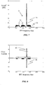
- 2 is quantized in magnitude to create a finite number of levels, which become classes. More specifically as shown in FIG. 3 , the power spectrum
- the value of ⁇ is selected so that the width of each class, r k - r k-1 , is on the same order as the expected echo ripple.
- the peak-to-peak ripple of the spectrum due to a -15 dB echo is 3 dB. In general, the peak-to-peak ripple will be larger.
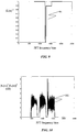
- the first grouping of neighboring bands is performed exploiting the knowledge that the spacing between echo peaks, e.g., 41, 43 as shown in FIG. 4 , must be less than 1 / T min . Beginning with the class having the highest power level, frequency bins belonging to the desired class are identified. If the desired class is detected twice within a frequency interval of 1 / T min without encountering an intermediate bin of a higher class, then all intermediate bins are reassigned to the desired class, thus creating a wider band. This grouping is applied sequentially for successively lower classes. This first grouping fills in between peaks (e.g., 41, 43 shown in FIG. 4 ) of the echo ripple. The resulting power spectrum has wider bands 51, 53, and 55.
- Bands are widened further using a second grouping, shown in FIG. 6 , that merges bands of neighboring classes when the lower power class is surrounding by two bands of the next higher class.
- the lower power class is reassigned to the higher power class, once again increasing the width of the bands.
- bands 51, 53 as shown in FIG. 5 which have a class indicated by quantization boundary 35, and the band therebetween that has a lower-power class indicated by quantization boundary 37, become wider band 63 shown in FIG. 6 .
- no minimum frequency interval for merging bands is required.
- This second grouping prevents a band from being fragmented when its ripple peaks straddle a quantization boundary.
- the resulting power spectrum shown in FIG. 6 has wider bands 63, 65, and 69, and transition regions 61 and 67.
- the power spectrum will be partitioned into bands that roughly correspond to the carrier bandwidths and the transition bands between carriers. If carrier bandwidths become fragmented into narrow bands, the variations associated with echo ripples can be lost during the normalization process. In some cases, the transition band may be fragmented; however, this is not a serious concern because the transition information is not reliable for residual echo estimation. Fragmentation of carrier bandwidths is undesirable, but can be tolerated if it is modest.
- the mean power per bin is computed by identifying bins with sufficient power (above a noise floor) and summing the power in each of those frequency bins, dividing by the number of bins.
- the inverse of the mean power becomes the spectral weighting of the desired filter response
- a minimum mean power level is defined, usually near the repeater noise level, so that idle portions of the spectrum are not amplified too greatly.
- a Matlab simulink program models the repeater. Matlab code is used to compute the echo cancellation coefficients.
- the input signal is a single EDGE carrier and a three-carrier Wideband Code Division Multiple Access (WCDMA) signal whose average power is 30 dB (gain term in simulink set to 0.03) below the EDGE carrier.
- WCDMA Wideband Code Division Multiple Access
- a noise spectrum would replace the WCDMA signal in an actual operation.
- the bandwidth of the EDGE carrier is too narrow to use the correlation method for echo cancellation. However, it is shown below that weighting the spectrum allows the use of the correlation method.
- the repeater spectrum 71 shown in FIG. 7 includes a residual echo.
- the residual echo power is 11 dB below the input signal power.
- the input is one-carrier EDGE 73 and 3-carrier Wideband Code Division Multiple Access (WCDMA) 75 at lower power. Ripples on the WCDMA signal 75 are clearly visible.
- FIG. 12 shows the repeater spectrum 121 when the residual echo is -17 dB. Note that the ripples within the WCDMA spectrum are more pronounced when the residual echo is -11 dB ( FIG. 7 ) as compared with -17 dB ( FIG. 12 ). It is also apparent that the EDGE carrier bandwidth is too narrow in both FIGS. 7 and 12 to view the echo ripples.
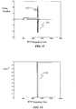
- the autocorrelation for the -11 dB residual echo is shown in FIG. 11 .
- the traces 111 and 113 are computed from the original and weight spectra, respectively. More specifically, the trace 111 is the autocorrelation computed from the original power spectrum 71 in FIG. 7 .
- the trace 113 is based on the weighted spectrum 101 in FIG. 10 .
- the autocorrelation for the -17 dB residual echo is shown in FIG 16 .
- the traces 161 and 163 are computed from the original and weight spectra, respectively. It can be seen that the masking by the EDGE carrier with the original power spectrum is still significant despite the reduction in the echo power.
- embodiments of the invention allow autocorrelation method to be applied to narrow bandwidth signals for echo cancellation. This is achieved by, for example, using a weighted power spectrum.
Landscapes
- Engineering & Computer Science (AREA)
- Computer Networks & Wireless Communication (AREA)
- Signal Processing (AREA)
- Radio Relay Systems (AREA)
Claims (14)
- Drahtloser Gleichfrequenz-Repeater (10), der Folgendes umfasst:eine Eingangsantenne (12), um ein Eingangssignal zu empfangen;eine Ausgangsantenne (13), um ein verstärktes Signal auszugeben;einen Verstärker (23), um das empfangene Eingangssignal zu verstärken und das verstärkte Ausgangssignal zur Antenne zu liefern;einen internen Rückkopplungspfad (150), um ein Echo zwischen der Ausgangsantenne (13) und der Eingangsantenne (12) durch Implementieren von Folgendem adaptiv zu unterdrücken:Messen eines Signals im internen Rückkopplungspfad (150); undAnwenden durch ein Filter (210) des drahtlosen Gleichfrequenz-Repeaters (10) einer Gewichtungsfunktion auf ein Leistungsspektrum eines gemessenen Rückkopplungssignals im drahtlosen Repeater (10) und dadurch Erhalten eines gewichteten Leistungsspektrums des gemessenen Signals;Erhalten einer Signalautokorrelation im internen Rückkopplungspfad (150) auf der Grundlage des gewichteten Leistungsspektrums des gemessenen Signals, wobei das Filter (210) eine Breite der Autokorrelation des Eingangssignals derart verringert, dass sie geringer als eine Schleifenverzögerung eines Echopfades ist;Detektieren eines Echos im internen Rückkopplungspfad auf der Grundlage der Signalautokorrelation undadaptives Unterdrücken des Echos im internen Rückkopplungspfad (150) auf der Grundlage des detektierten Echos.
- Drahtloser Repeater nach Anspruch 1, wobei- der interne Rückkopplungspfad einen digitalen Verstärkungsblock (153) umfasst und das gemessene Rückkopplungssignal vor dem digitalen Verstärkungsblock gemessen wird;- der interne Rückkopplungspfad einen Abschnitt einer digitalen IF-Stufe umfasst, wobei die digitale IF-Stufe ferner einen digitalen Signalprozessor (15a, 15b), der den adaptiven Algorithmus zum Unterdrücken von Echos implementiert, umfasst;- die Gewichtsfunktion ein Leistungsspektrum des Eingangssignalrauschens weißt oder- die Gewichtsfunktion Echowelligkeiten im Leistungsspektrum des gemessenen Rückkopplungssignals erhält.
- Drahtloser Repeater nach Anspruch 1, wobei die Gewichtsfunktion die Leistung eines Trägers im gemessenen Rückkopplungssignal derart anpasst, dass dann, wenn mehrere Träger enthalten sind, jeder Träger durchschnittlich dieselbe Leistungsdichte besitzt und dann, wenn ein einzelner Träger enthalten ist, die Leistungsdichte des einzelnen Trägers derart verringert ist, dass sie mit einem Grundrauschen des Repeaters übereinstimmt.
- Verfahren zur Echounterdrückung in einem drahtlosen Gleichfrequenz-Repeater (10), das Folgendes umfasst:Empfangen eines Eingangssignals mit einer Eingangsantenne (12);Verstärken des empfangenen Eingangssignals mit einem Verstärker (23) und Liefern des verstärkten Ausgangssignals zu einer Ausgangsantenne (13);Ausgeben des verstärkten Signals mit der Ausgangsantenne (13);Messen eines Signals in einem internen Rückkopplungspfad des drahtlosen Gleichfrequenz-Repeaters;Filtern, um eine spektrale Merkmalsgewichtungsfunktion auf ein Leistungsspektrum des gemessenen Signals anzuwenden, um ein gewichtetes Leistungsspektrum des gemessenen Signals zu erhalten;Erhalten einer Signalautokorrelation im internen Rückkopplungspfad des drahtlosen Gleichfrequenz-Repeaters auf der Grundlage des gewichteten Leistungsspektrums; wobeidas gewichtete Leistungsspektrum eine Breite der Signalautokorrelation derart verringert, dass sie geringer als eine Schleifenverzögerung eines Echopfades ist;Detektieren eines Echos im internen Rückkopplungspfad auf der Grundlage der Signalautokorrelation undadaptives Unterdrücken des Echos im internen Rückkopplungspfad auf der Grundlage des detektierten Echos.
- Verfahren nach Anspruch 4, wobei das Anwenden der spektralen Gewichtsfunktion ein Filtern des gemessenen Signals umfasst.
- Verfahren nach Anspruch 4, wobei das Eingangssignal im internen Rückkopplungspfad ein Schmalbandsignal umfasst, das eine überlappende Autokorrelation zwischen dem Echo und dem gemessenen Signal vor dem Anwenden der spektralen Gewichtsfunktion besitzt.
- Verfahren nach Anspruch 4, das ferner Folgendes umfasst: Erhalten der spektralen Gewichtsfunktion auf der Grundlage eines Eingangsspektrums ohne Echo.
- Verfahren nach Anspruch 7, das ferner Folgendes umfasst: Schätzen des Eingangsspektrums durch Anpassen des Leistungsspektrums des gemessenen Signals an ein Modell auf der Grundlage des Modulationsformates des Eingangssignals im internen Rückkopplungspfad.
- Verfahren nach Anspruch 8, das ferner ein Quantisieren des Leistungsspektrums des gemessenen Signals zu mehreren Pegeln umfasst, wobei das Quantisieren des Leistungsspektrums ferner logarithmisches Quantisieren umfasst.
- Verfahren nach Anspruch 9, wobei das Leistungsspektrum als eine Funktion von mehreren Frequenzbereichswerten konfiguriert ist und das Verfahren ferner Folgendes umfasst:Gruppieren von Werten im Leistungsspektrum, um Bänder zu bilden, die breiter als die Frequenzbereichswerte sind;Erhalten einer Durchschnittsleistung der Bänder undBerechnen der spektralen Gewichtsfunktion unter Verwendung eines Kehrwertes der Durchschnittsleistung.
- Verfahren nach Anspruch 4, wobei die spektrale Gewichtsfunktion auf dem Eingangssignal und einem Rauschsignalspektrum ohne Effekte des Echos basiert.
- Verfahren nach Anspruch 4, das ferner ein Unterteilen des Leistungsspektrums in disjunkte Bänder durch Gruppieren von Frequenzbereichswerten auf der Grundlage einer gemessenen Leistungsdichte in benachbarte Bänder umfasst.
- Verfahren nach Anspruch 12, das ferner das Normieren einer Leistung jedes Bandes derart umfasst, dass eine spektrale Leistungsdichte jedes Bandes einem Bezugspegel gleicht.
- Kommunikationssystem, das eine Basisstation (100) und einen drahtlosen Repeater nach Anspruch 1 umfasst.
Applications Claiming Priority (2)
| Application Number | Priority Date | Filing Date | Title |
|---|---|---|---|
| US89711207P | 2007-01-24 | 2007-01-24 | |
| PCT/US2008/000738 WO2008091556A1 (en) | 2007-01-24 | 2008-01-22 | Adaptive echo cancellation for an on-frequency rf repeater using a weighted power spectrum |
Publications (3)
| Publication Number | Publication Date |
|---|---|
| EP2119028A1 EP2119028A1 (de) | 2009-11-18 |
| EP2119028A4 EP2119028A4 (de) | 2014-01-08 |
| EP2119028B1 true EP2119028B1 (de) | 2019-02-27 |
Family
ID=39641732
Family Applications (1)
| Application Number | Title | Priority Date | Filing Date |
|---|---|---|---|
| EP08713187.6A Active EP2119028B1 (de) | 2007-01-24 | 2008-01-22 | Adaptive echounterdrückung für einen hf-gleichfrequenzverstärker mit gewichtetem leistungsspektrum |
Country Status (3)
| Country | Link |
|---|---|
| US (1) | US8068783B2 (de) |
| EP (1) | EP2119028B1 (de) |
| WO (1) | WO2008091556A1 (de) |
Families Citing this family (19)
| Publication number | Priority date | Publication date | Assignee | Title |
|---|---|---|---|---|
| US7715785B2 (en) * | 2006-04-21 | 2010-05-11 | Powerwave Technologies, Inc. | System and method for estimation and compensation of radiated feedback coupling in a high gain repeater |
| JP5134016B2 (ja) * | 2007-03-02 | 2013-01-30 | クゥアルコム・インコーポレイテッド | 信号品質を向上させるためのオンライン中継器と連携した適応アンテナアレイの使用 |
| US8385820B2 (en) * | 2009-01-12 | 2013-02-26 | Telefonaktiebolaget Lm Ericsson (Publ) | Systems and method for canceling feedback interference |
| US8358969B2 (en) | 2009-05-11 | 2013-01-22 | Qualcomm Incorporated | Feedback delay control in an echo cancellation repeater |
| US9049065B2 (en) * | 2009-05-11 | 2015-06-02 | Qualcomm Incorporated | Removal of ICI/ISI errors in frequency domain channel estimation for wireless repeaters |
| US8452230B2 (en) | 2009-05-11 | 2013-05-28 | Qualcomm Incorporated | Multi-metric gain control for wireless repeater |
| US8611227B2 (en) * | 2009-05-11 | 2013-12-17 | Qualcomm Incorporated | Channel estimate pruning in presence of large signal dynamics in an interference cancellation repeater |
| US8364076B2 (en) * | 2009-09-18 | 2013-01-29 | Electronics And Telecommunications Research Institute | Apparatus and method of feedback cancellation for radio signal |
| US8548375B2 (en) * | 2010-03-12 | 2013-10-01 | Qualcomm Incorporated | Gain control metric computation in a wireless repeater |
| US8559485B2 (en) * | 2010-04-08 | 2013-10-15 | Andrew Llc | Autoregressive signal processing for repeater echo cancellation |
| US8630211B2 (en) | 2010-06-30 | 2014-01-14 | Qualcomm Incorporated | Hybrid radio architecture for repeaters using RF cancellation reference |
| EP2619916B1 (de) * | 2010-09-21 | 2017-08-16 | CommScope Technologies LLC | Mehrweg-interferenzunterdrückung mittels cepstrum-analyse |
| US20130034128A1 (en) * | 2011-08-05 | 2013-02-07 | Qualcomm Incorporated | Echo cancellation repeater operation in the absence of an input signal |
| JP5825175B2 (ja) * | 2012-03-29 | 2015-12-02 | 富士通株式会社 | 無線通信機 |
| US11031994B2 (en) | 2016-11-15 | 2021-06-08 | Wilson Electronics, Llc | Signal booster for boosting signals in contiguous bands |
| US10305706B2 (en) | 2017-03-01 | 2019-05-28 | Capacicom Ltd. | Synchronized interference suppression in frequency domain |
| US11218237B2 (en) | 2018-09-27 | 2022-01-04 | Wilson Electronics, Llc | Intermediate frequency (IF) filtering for enhanced crossover attenuation in a repeater |
| AU2022323271A1 (en) * | 2021-08-04 | 2024-02-08 | Arris Enterprises Llc | Machine learning for rf impairment detection |
| CN116437435B (zh) * | 2021-12-30 | 2026-01-16 | 华为技术有限公司 | 定位服务器、定位方法和背反射通信系统 |
Family Cites Families (11)
| Publication number | Priority date | Publication date | Assignee | Title |
|---|---|---|---|---|
| JPH10275080A (ja) * | 1997-01-24 | 1998-10-13 | Texas Instr Inc <Ti> | マイクロプロセッサ |
| EP1039716B1 (de) | 1999-03-25 | 2003-04-16 | Kabushiki Kaisha Toshiba | Zwischenverstärker eines OFDM-Übertragungssignals und Empfänger |
| JP3540686B2 (ja) * | 1999-09-30 | 2004-07-07 | 株式会社東芝 | Ofdm用周波数特性補償器 |
| US20020181699A1 (en) * | 2001-03-23 | 2002-12-05 | Tien Pham | System for convolutional echo cancellation by iterative autocorrelation |
| DE10155179B4 (de) * | 2001-11-12 | 2006-11-23 | Andrew Wireless Systems Gmbh | Digitaler Repeater mit Bandpassfilterung, adaptiver Vorentzerrung und Unterdrückung der Eigenschwingung |
| US7355993B2 (en) * | 2002-06-27 | 2008-04-08 | Adkins Keith L | Method and apparatus for forward link gain control in a power controlled repeater |
| AU2003242626A1 (en) * | 2002-07-17 | 2004-02-02 | Telefonaktiebolaget Lm Ericsson (Publ) | Noise whitening |
| US7454167B2 (en) * | 2004-07-14 | 2008-11-18 | Samsung Electronics Co., Ltd. | Apparatus and method for echo cancellation in a wireless repeater using cross-polarized antenna elements |
| US7596352B2 (en) * | 2004-08-23 | 2009-09-29 | Samsung Electronics Co., Ltd. | Apparatus and method for channel estimation and echo cancellation in a wireless repeater |
| US7844216B2 (en) * | 2004-09-07 | 2010-11-30 | Samsung Electronics Co., Ltd. | Wireless repeater using a single RF chain for use in a TDD wireless network |
| US7715785B2 (en) * | 2006-04-21 | 2010-05-11 | Powerwave Technologies, Inc. | System and method for estimation and compensation of radiated feedback coupling in a high gain repeater |
-
2008
- 2008-01-22 WO PCT/US2008/000738 patent/WO2008091556A1/en not_active Ceased
- 2008-01-22 EP EP08713187.6A patent/EP2119028B1/de active Active
- 2008-01-22 US US12/009,667 patent/US8068783B2/en not_active Expired - Fee Related
Non-Patent Citations (1)
| Title |
|---|
| None * |
Also Published As
| Publication number | Publication date |
|---|---|
| EP2119028A4 (de) | 2014-01-08 |
| WO2008091556A1 (en) | 2008-07-31 |
| EP2119028A1 (de) | 2009-11-18 |
| US8068783B2 (en) | 2011-11-29 |
| US20080176513A1 (en) | 2008-07-24 |
Similar Documents
| Publication | Publication Date | Title |
|---|---|---|
| EP2119028B1 (de) | Adaptive echounterdrückung für einen hf-gleichfrequenzverstärker mit gewichtetem leistungsspektrum | |
| US8559485B2 (en) | Autoregressive signal processing for repeater echo cancellation | |
| US8073385B2 (en) | Adaptive echo cancellation for an on-frequency RF repeater with digital sub-band filtering | |
| US10382089B2 (en) | Systems and methods for intelligently-tuned digital self-interference cancellation | |
| CN105594131B (zh) | 减少通信系统自干扰信号的方法和装置 | |
| US10284356B2 (en) | Self-interference cancellation | |
| US7983635B2 (en) | System and method for controlling intermodulation interference | |
| US20050259721A1 (en) | Noise power estimation apparatus, noise power estimation method and signal detection apparatus | |
| EP2441176B1 (de) | Lastschätzung in störungsweissungssystemen | |
| US20110116386A1 (en) | Transmission control in a wireless communication system | |
| US20090304125A1 (en) | Iterative receiver and method for detecting transmitted signal thereof | |
| EP2713522A1 (de) | Digitale Nachverzerrungskompensation in Telekommunikationssystemen | |
| CN102934478B (zh) | 频域预均衡系统中的负载估计 | |
| US20180070364A1 (en) | Interference mitigation via space-time subspace projection | |
| TW201635721A (zh) | 用於接收器之發信降噪方法及其裝置 | |
| US20180351588A1 (en) | Cancellation device, cancellation method, and wireless communication apparatus | |
| EP2622753B1 (de) | Wiederverwendung einer kovarianzmatrix | |
| US8576965B2 (en) | Methods and systems for interference cancellation in multi-mode coexistence modems | |
| EP4369615A1 (de) | Interferenzunterdrückungsschaltung und betriebsverfahren dafür | |
| US7924904B2 (en) | RF band clock spur harmonic canceller | |
| Attar et al. | Towards adaptive digital self-interference cancellation in full-duplex wireless transceivers: APSM vs. neural networks | |
| Braithwaite et al. | Adaptive echo cancellation for an on-frequency RF repeater using a weighted power spectrum | |
| US9775049B2 (en) | Radio communication apparatus and interference detection method | |
| EP3048739B1 (de) | Interferenzunterdrückungsverfahren und -vorrichtung | |
| Ploder et al. | A neural network approach for the cancellation of the second-order-intermodulation distortion in future cellular RF transceivers |
Legal Events
| Date | Code | Title | Description |
|---|---|---|---|
| PUAI | Public reference made under article 153(3) epc to a published international application that has entered the european phase |
Free format text: ORIGINAL CODE: 0009012 |
|
| 17P | Request for examination filed |
Effective date: 20090721 |
|
| AK | Designated contracting states |
Kind code of ref document: A1 Designated state(s): AT BE BG CH CY CZ DE DK EE ES FI FR GB GR HR HU IE IS IT LI LT LU LV MC MT NL NO PL PT RO SE SI SK TR |
|
| DAX | Request for extension of the european patent (deleted) | ||
| A4 | Supplementary search report drawn up and despatched |
Effective date: 20131206 |
|
| RIC1 | Information provided on ipc code assigned before grant |
Ipc: H04B 7/15 20060101AFI20131202BHEP |
|
| RAP1 | Party data changed (applicant data changed or rights of an application transferred) |
Owner name: P-WAVE HOLDINGS, LLC |
|
| RAP1 | Party data changed (applicant data changed or rights of an application transferred) |
Owner name: POWERWAVE TECHNOLOGIES S.A.R.L. |
|
| RAP1 | Party data changed (applicant data changed or rights of an application transferred) |
Owner name: INTEL CORPORATION |
|
| STAA | Information on the status of an ep patent application or granted ep patent |
Free format text: STATUS: EXAMINATION IS IN PROGRESS |
|
| 17Q | First examination report despatched |
Effective date: 20170717 |
|
| GRAP | Despatch of communication of intention to grant a patent |
Free format text: ORIGINAL CODE: EPIDOSNIGR1 |
|
| STAA | Information on the status of an ep patent application or granted ep patent |
Free format text: STATUS: GRANT OF PATENT IS INTENDED |
|
| INTG | Intention to grant announced |
Effective date: 20180920 |
|
| GRAS | Grant fee paid |
Free format text: ORIGINAL CODE: EPIDOSNIGR3 |
|
| GRAA | (expected) grant |
Free format text: ORIGINAL CODE: 0009210 |
|
| STAA | Information on the status of an ep patent application or granted ep patent |
Free format text: STATUS: THE PATENT HAS BEEN GRANTED |
|
| AK | Designated contracting states |
Kind code of ref document: B1 Designated state(s): AT BE BG CH CY CZ DE DK EE ES FI FR GB GR HR HU IE IS IT LI LT LU LV MC MT NL NO PL PT RO SE SI SK TR |
|
| REG | Reference to a national code |
Ref country code: GB Ref legal event code: FG4D |
|
| REG | Reference to a national code |
Ref country code: CH Ref legal event code: EP |
|
| REG | Reference to a national code |
Ref country code: AT Ref legal event code: REF Ref document number: 1102851 Country of ref document: AT Kind code of ref document: T Effective date: 20190315 |
|
| REG | Reference to a national code |
Ref country code: IE Ref legal event code: FG4D |
|
| REG | Reference to a national code |
Ref country code: DE Ref legal event code: R096 Ref document number: 602008059115 Country of ref document: DE |
|
| REG | Reference to a national code |
Ref country code: NL Ref legal event code: FP |
|
| REG | Reference to a national code |
Ref country code: LT Ref legal event code: MG4D |
|
| PG25 | Lapsed in a contracting state [announced via postgrant information from national office to epo] |
Ref country code: NO Free format text: LAPSE BECAUSE OF FAILURE TO SUBMIT A TRANSLATION OF THE DESCRIPTION OR TO PAY THE FEE WITHIN THE PRESCRIBED TIME-LIMIT Effective date: 20190527 Ref country code: PT Free format text: LAPSE BECAUSE OF FAILURE TO SUBMIT A TRANSLATION OF THE DESCRIPTION OR TO PAY THE FEE WITHIN THE PRESCRIBED TIME-LIMIT Effective date: 20190627 Ref country code: SE Free format text: LAPSE BECAUSE OF FAILURE TO SUBMIT A TRANSLATION OF THE DESCRIPTION OR TO PAY THE FEE WITHIN THE PRESCRIBED TIME-LIMIT Effective date: 20190227 Ref country code: LT Free format text: LAPSE BECAUSE OF FAILURE TO SUBMIT A TRANSLATION OF THE DESCRIPTION OR TO PAY THE FEE WITHIN THE PRESCRIBED TIME-LIMIT Effective date: 20190227 Ref country code: FI Free format text: LAPSE BECAUSE OF FAILURE TO SUBMIT A TRANSLATION OF THE DESCRIPTION OR TO PAY THE FEE WITHIN THE PRESCRIBED TIME-LIMIT Effective date: 20190227 |
|
| PG25 | Lapsed in a contracting state [announced via postgrant information from national office to epo] |
Ref country code: BG Free format text: LAPSE BECAUSE OF FAILURE TO SUBMIT A TRANSLATION OF THE DESCRIPTION OR TO PAY THE FEE WITHIN THE PRESCRIBED TIME-LIMIT Effective date: 20190527 Ref country code: IS Free format text: LAPSE BECAUSE OF FAILURE TO SUBMIT A TRANSLATION OF THE DESCRIPTION OR TO PAY THE FEE WITHIN THE PRESCRIBED TIME-LIMIT Effective date: 20190627 Ref country code: HR Free format text: LAPSE BECAUSE OF FAILURE TO SUBMIT A TRANSLATION OF THE DESCRIPTION OR TO PAY THE FEE WITHIN THE PRESCRIBED TIME-LIMIT Effective date: 20190227 Ref country code: LV Free format text: LAPSE BECAUSE OF FAILURE TO SUBMIT A TRANSLATION OF THE DESCRIPTION OR TO PAY THE FEE WITHIN THE PRESCRIBED TIME-LIMIT Effective date: 20190227 Ref country code: GR Free format text: LAPSE BECAUSE OF FAILURE TO SUBMIT A TRANSLATION OF THE DESCRIPTION OR TO PAY THE FEE WITHIN THE PRESCRIBED TIME-LIMIT Effective date: 20190528 |
|
| REG | Reference to a national code |
Ref country code: AT Ref legal event code: MK05 Ref document number: 1102851 Country of ref document: AT Kind code of ref document: T Effective date: 20190227 |
|
| PG25 | Lapsed in a contracting state [announced via postgrant information from national office to epo] |
Ref country code: SK Free format text: LAPSE BECAUSE OF FAILURE TO SUBMIT A TRANSLATION OF THE DESCRIPTION OR TO PAY THE FEE WITHIN THE PRESCRIBED TIME-LIMIT Effective date: 20190227 Ref country code: DK Free format text: LAPSE BECAUSE OF FAILURE TO SUBMIT A TRANSLATION OF THE DESCRIPTION OR TO PAY THE FEE WITHIN THE PRESCRIBED TIME-LIMIT Effective date: 20190227 Ref country code: ES Free format text: LAPSE BECAUSE OF FAILURE TO SUBMIT A TRANSLATION OF THE DESCRIPTION OR TO PAY THE FEE WITHIN THE PRESCRIBED TIME-LIMIT Effective date: 20190227 Ref country code: RO Free format text: LAPSE BECAUSE OF FAILURE TO SUBMIT A TRANSLATION OF THE DESCRIPTION OR TO PAY THE FEE WITHIN THE PRESCRIBED TIME-LIMIT Effective date: 20190227 Ref country code: CZ Free format text: LAPSE BECAUSE OF FAILURE TO SUBMIT A TRANSLATION OF THE DESCRIPTION OR TO PAY THE FEE WITHIN THE PRESCRIBED TIME-LIMIT Effective date: 20190227 Ref country code: IT Free format text: LAPSE BECAUSE OF FAILURE TO SUBMIT A TRANSLATION OF THE DESCRIPTION OR TO PAY THE FEE WITHIN THE PRESCRIBED TIME-LIMIT Effective date: 20190227 Ref country code: EE Free format text: LAPSE BECAUSE OF FAILURE TO SUBMIT A TRANSLATION OF THE DESCRIPTION OR TO PAY THE FEE WITHIN THE PRESCRIBED TIME-LIMIT Effective date: 20190227 |
|
| REG | Reference to a national code |
Ref country code: DE Ref legal event code: R097 Ref document number: 602008059115 Country of ref document: DE |
|
| PG25 | Lapsed in a contracting state [announced via postgrant information from national office to epo] |
Ref country code: PL Free format text: LAPSE BECAUSE OF FAILURE TO SUBMIT A TRANSLATION OF THE DESCRIPTION OR TO PAY THE FEE WITHIN THE PRESCRIBED TIME-LIMIT Effective date: 20190227 |
|
| PG25 | Lapsed in a contracting state [announced via postgrant information from national office to epo] |
Ref country code: AT Free format text: LAPSE BECAUSE OF FAILURE TO SUBMIT A TRANSLATION OF THE DESCRIPTION OR TO PAY THE FEE WITHIN THE PRESCRIBED TIME-LIMIT Effective date: 20190227 |
|
| PLBE | No opposition filed within time limit |
Free format text: ORIGINAL CODE: 0009261 |
|
| STAA | Information on the status of an ep patent application or granted ep patent |
Free format text: STATUS: NO OPPOSITION FILED WITHIN TIME LIMIT |
|
| 26N | No opposition filed |
Effective date: 20191128 |
|
| PG25 | Lapsed in a contracting state [announced via postgrant information from national office to epo] |
Ref country code: SI Free format text: LAPSE BECAUSE OF FAILURE TO SUBMIT A TRANSLATION OF THE DESCRIPTION OR TO PAY THE FEE WITHIN THE PRESCRIBED TIME-LIMIT Effective date: 20190227 |
|
| PGFP | Annual fee paid to national office [announced via postgrant information from national office to epo] |
Ref country code: FR Payment date: 20191230 Year of fee payment: 13 |
|
| PG25 | Lapsed in a contracting state [announced via postgrant information from national office to epo] |
Ref country code: TR Free format text: LAPSE BECAUSE OF FAILURE TO SUBMIT A TRANSLATION OF THE DESCRIPTION OR TO PAY THE FEE WITHIN THE PRESCRIBED TIME-LIMIT Effective date: 20190227 |
|
| PGFP | Annual fee paid to national office [announced via postgrant information from national office to epo] |
Ref country code: DE Payment date: 20200107 Year of fee payment: 13 Ref country code: GB Payment date: 20200115 Year of fee payment: 13 Ref country code: NL Payment date: 20200130 Year of fee payment: 13 |
|
| PG25 | Lapsed in a contracting state [announced via postgrant information from national office to epo] |
Ref country code: MC Free format text: LAPSE BECAUSE OF FAILURE TO SUBMIT A TRANSLATION OF THE DESCRIPTION OR TO PAY THE FEE WITHIN THE PRESCRIBED TIME-LIMIT Effective date: 20190227 |
|
| REG | Reference to a national code |
Ref country code: CH Ref legal event code: PL |
|
| REG | Reference to a national code |
Ref country code: BE Ref legal event code: MM Effective date: 20200131 |
|
| PG25 | Lapsed in a contracting state [announced via postgrant information from national office to epo] |
Ref country code: LU Free format text: LAPSE BECAUSE OF NON-PAYMENT OF DUE FEES Effective date: 20200122 |
|
| PG25 | Lapsed in a contracting state [announced via postgrant information from national office to epo] |
Ref country code: BE Free format text: LAPSE BECAUSE OF NON-PAYMENT OF DUE FEES Effective date: 20200131 Ref country code: LI Free format text: LAPSE BECAUSE OF NON-PAYMENT OF DUE FEES Effective date: 20200131 Ref country code: CH Free format text: LAPSE BECAUSE OF NON-PAYMENT OF DUE FEES Effective date: 20200131 |
|
| PG25 | Lapsed in a contracting state [announced via postgrant information from national office to epo] |
Ref country code: IE Free format text: LAPSE BECAUSE OF NON-PAYMENT OF DUE FEES Effective date: 20200122 |
|
| REG | Reference to a national code |
Ref country code: DE Ref legal event code: R119 Ref document number: 602008059115 Country of ref document: DE |
|
| REG | Reference to a national code |
Ref country code: NL Ref legal event code: MM Effective date: 20210201 |
|
| GBPC | Gb: european patent ceased through non-payment of renewal fee |
Effective date: 20210122 |
|
| PG25 | Lapsed in a contracting state [announced via postgrant information from national office to epo] |
Ref country code: FR Free format text: LAPSE BECAUSE OF NON-PAYMENT OF DUE FEES Effective date: 20210131 Ref country code: NL Free format text: LAPSE BECAUSE OF NON-PAYMENT OF DUE FEES Effective date: 20210201 |
|
| PG25 | Lapsed in a contracting state [announced via postgrant information from national office to epo] |
Ref country code: GB Free format text: LAPSE BECAUSE OF NON-PAYMENT OF DUE FEES Effective date: 20210122 Ref country code: DE Free format text: LAPSE BECAUSE OF NON-PAYMENT OF DUE FEES Effective date: 20210803 |
|
| PG25 | Lapsed in a contracting state [announced via postgrant information from national office to epo] |
Ref country code: MT Free format text: LAPSE BECAUSE OF FAILURE TO SUBMIT A TRANSLATION OF THE DESCRIPTION OR TO PAY THE FEE WITHIN THE PRESCRIBED TIME-LIMIT Effective date: 20190227 Ref country code: CY Free format text: LAPSE BECAUSE OF FAILURE TO SUBMIT A TRANSLATION OF THE DESCRIPTION OR TO PAY THE FEE WITHIN THE PRESCRIBED TIME-LIMIT Effective date: 20190227 |