EP2119079B1 - Procédé et appareil pour une réutilisation de ressources dans un système de communication - Google Patents
Procédé et appareil pour une réutilisation de ressources dans un système de communication Download PDFInfo
- Publication number
- EP2119079B1 EP2119079B1 EP07748397.2A EP07748397A EP2119079B1 EP 2119079 B1 EP2119079 B1 EP 2119079B1 EP 07748397 A EP07748397 A EP 07748397A EP 2119079 B1 EP2119079 B1 EP 2119079B1
- Authority
- EP
- European Patent Office
- Prior art keywords
- data sending
- data
- future transmit
- future
- units
- Prior art date
- Legal status (The legal status is an assumption and is not a legal conclusion. Google has not performed a legal analysis and makes no representation as to the accuracy of the status listed.)
- Active
Links
Images


Classifications
-
- H—ELECTRICITY
- H04—ELECTRIC COMMUNICATION TECHNIQUE
- H04W—WIRELESS COMMUNICATION NETWORKS
- H04W4/00—Services specially adapted for wireless communication networks; Facilities therefor
- H04W4/18—Information format or content conversion, e.g. adaptation by the network of the transmitted or received information for the purpose of wireless delivery to users or terminals
-
- H—ELECTRICITY
- H04—ELECTRIC COMMUNICATION TECHNIQUE
- H04W—WIRELESS COMMUNICATION NETWORKS
- H04W72/00—Local resource management
- H04W72/20—Control channels or signalling for resource management
-
- H—ELECTRICITY
- H04—ELECTRIC COMMUNICATION TECHNIQUE
- H04B—TRANSMISSION
- H04B2201/00—Indexing scheme relating to details of transmission systems not covered by a single group of H04B3/00 - H04B13/00
- H04B2201/69—Orthogonal indexing scheme relating to spread spectrum techniques in general
- H04B2201/707—Orthogonal indexing scheme relating to spread spectrum techniques in general relating to direct sequence modulation
- H04B2201/7097—Direct sequence modulation interference
- H04B2201/709727—GRAKE type RAKE receivers
-
- H—ELECTRICITY
- H04—ELECTRIC COMMUNICATION TECHNIQUE
- H04W—WIRELESS COMMUNICATION NETWORKS
- H04W48/00—Access restriction; Network selection; Access point selection
- H04W48/08—Access restriction or access information delivery, e.g. discovery data delivery
-
- H—ELECTRICITY
- H04—ELECTRIC COMMUNICATION TECHNIQUE
- H04W—WIRELESS COMMUNICATION NETWORKS
- H04W72/00—Local resource management
- H04W72/50—Allocation or scheduling criteria for wireless resources
- H04W72/54—Allocation or scheduling criteria for wireless resources based on quality criteria
- H04W72/541—Allocation or scheduling criteria for wireless resources based on quality criteria using the level of interference
Definitions
- the present invention generally relates to communication systems, such as cellular communication networks, and particularly relates to a method and system for statistically reusing resources, such as spreading codes or carrier tones, in communication systems.
- a remote receiver evaluates received signal quality, determines the received data rate it can support at that quality, and returns a corresponding data rate request to the originating transmitter. In response, the transmitter uses the requested data rate to adjust its next transmission to the receiver.
- Implicit in such systems is the notion that the receiver's reception conditions during the time interval in which the transmitter uses the adapted data rate are the same (or close enough) to the reception conditions existent when the receiver made its signal quality determination.
- at least some current (and many developing network standards) provide high-speed packet data services in which packet data incoming to the network for delivery to remote receivers generally has a random arrival distribution. That is, for some transmit intervals, some network transmitters have little or no data to send, while others have large amounts of data to send.
- the individual transmission activities for packet data within a given group of network transmitters may vary widely over successive transmission intervals. Compounding these activity variations, there is a tendency for given network transmitters to allocate significant transmit power and/or other transmit resources if there is packet data to send in any given interval, as a basis for sending data at the highest achievable rate within that interval. With that approach, the interference caused by a transmitter with respect to receivers operating in surrounding areas can vary dramatically over successive transmit intervals, as a function of whether the transmitter has packet data to send, and, if so, as a function of the transmit resource allocations made by the transmitter for sending that data.
- a given receiver may compute received signal quality at a time instant where one (or more) nearby transmitters are actively sending packet data, meaning that the receiver's signal quality calculation reflects the potentially high levels of interference caused by the nearby, active transmitters.
- the level of interference experienced by the receiver will be lower and its previously calculated signal quality will be overly pessimistic for those conditions. Consequently, the receiver will be underserved during the low interference condition, to the extent that the receiver's supporting transmitter has adapted its transmission link to the receiver based on the previously calculated signal quality.
- Document WO 00/51390 A1 discloses a method and a system for allocating radio channel for communication between a base station and UE.
- “predictive" link adaptation provides a basis for capitalizing on future conditions of expected low interference as part of the ongoing transmit link adaptation process.
- HSDPA High Speed Downlink Packet Access
- WCDMA Wideband Code Division Multiple Access
- mobile stations are notified about how nearby data sending units 10 plan to use transmission resources in one or more future transmit intervals, thereby allowing the mobile stations to know with greater accuracy the data rate they can request for service during the future transmit interval(s).
- methods and apparatuses taught herein provide for predictive link adaptation, wherein data sending units provide indications of their transmit resource allocations for a future time interval, and the data receiving units correspondingly use that beforehand knowledge to determine link adaptation feedback in advance of the future time interval.
- a method of link adaptation in a wireless communication network according to claim 1 a data sending unit for use in a wireless communication network according to claim 9, a method of supporting link adaptation for use in a data receiving unit configured for operation in a wireless communication network according to claim 19 and a data receiving unit configured for operation in a wireless communication network according to claim 24.
- a method of link adaptation in a wireless communication network includes signaling future transmit resource allocations for a future transmit interval from one or more data sending units, so that nearby data receiving units can consider the future transmit resource allocations in their interference-based determinations of link adaptation feedback for the future transmit intervals.
- the method also includes, at a given data sending unit, receiving link adaptation feedback for the future transmit interval in advance from an associated one of the data receiving units and, for the future interval, adapting a transmission link at the given data sending unit for the associated data receiving unit according to the link adaptation feedback.
- signaling future transmit resource allocations comprises transmitting an indication of whether the data sending unit will be active with respect to one or more types of transmission in the future transmit interval.
- signaling future transmit resource allocations for a future transmit interval from one or more data sending units comprises, for each of one or more of the data sending units, transmitting an indication of whether one or more data sending units will be transmitting in the future transmit interval.
- data receiving units are configured to determine link adaptation feedback for the future transmit interval based on considering or not considering an interference contribution of the individual data sending units according to the corresponding indications of whether the data sending unit will be active.
- the data sending units signal future transmit resource allocations in more detail, such as by transmitting information about channelization resource allocations, e.g., information regarding channelization codes and/or carrier frequencies.
- information about channelization resource allocations e.g., information regarding channelization codes and/or carrier frequencies.
- Such information may include, for example, code and/or frequency assignments for particular types of transmit channels, and may include information regarding the transmit power allocations, data rates, etc., for given channelization resources.
- individual data receiving units can determine link adaptation feedback for the future time interval by predicting interference conditions for the future transmit interval.
- a data receiving unit method includes estimating interference contributions of individual data sending units (for the future transmit interval) according to the corresponding channelization resource allocation information.
- an individual data receiving unit can be configured to estimate interference conditions for the future transmit interval by determining signal impairment cross-correlations based on knowledge of the corresponding channelization code or channelization frequency allocations.
- Fig. 1 illustrates a wireless communication network 8, which includes a number of data sending units 10, each configured to support communication with one or more (remote) data receiving units 12.
- one or more of the data sending units 10 signal future transmit resource allocations for a future transmit interval, thereby enabling appropriately configured ones of the data receiving units 12 to determine link adaptation feedback for that future transmit interval based on knowledge of the future transmit resource allocations.
- a given data receiving unit 12 is provided advance information regarding the transmit resource allocations to be used at one or more of the data sending units 10.
- advance information regarding the transmit resource allocations to be used at one or more of the data sending units 10.
- a data sending unit 10-1 provides service in a cell C1, having a number of service sectors S1-S3.
- a data sending unit 10-2 provides service in sectors S1-S3 of cell C2
- a data sending unit 10-3 provides service in sectors S1-S3 of cell C3.
- the cells/sector coverage overlaps, such that a data sending unit 12-1 operating in sector S2 of cell C1 may be supported by the data sending unit 10-1, but it "hears" interfering transmissions from one or more of the nearby data sending units 10-2 and 10-3.
- each data sending unit 10 causes other cell/sector interference with respect to surrounding data receiving units 12.
- any given transmit interval whether and to what extent a nearby data sending unit 10 causes interference at a given data receiving unit 12 depends on the particular transmit activity of that data sending unit 10 during the given transmit interval. For example, certain channelization resources, such as channelization codes, channelization time slots, and/or channelization frequencies may be reused across the data sending units 10. Thus, the extent to which neighboring data sending units 10 simultaneously transmit different information using the same channelization resources represents a significant factor bearing on the amount and nature of reception interference experienced by a given data receiving unit 12 that is in range of the (potentially) interfering data sending units 10.
- one embodiment taught herein relates to the transmit power used to signal the future transmit resource allocations. More particularly, at least one embodiment taught herein includes signaling future transmit resource allocations using a signal power greater than that allocated to other control signals transmitted by the data sending unit. Doing so enhances reception of the signal for those data receiving units 10 outside of conventional signaling reception but still subject to interference caused by the data sending unit 10.
- a given data sending unit 10 can be configured to transmit indications of future resource allocations using a relatively high signal power (as compared to other control/overhead channel signaling), so that data receiving units 12 in nearby cells/sectors receive such information with improved reliability.
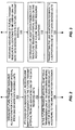
- Fig. 2 outlines a broad embodiment of a method of link adaptation in a wireless communication network that can be carried out by appropriately configured ones of the data sending units 10.
- the method "begins" with the data sending unit signaling future transmit resource allocations for a future transmit interval (Step 100).
- the data sending unit 10 can be configured to schedule transmissions to supported users (data receiving units 12) over a series of Transmit Time Intervals (TTIs).
- TTIs Transmit Time Intervals
- signaling future transmit resource allocations comprises, in at least one embodiment, the data sending unit 10 signaling an indication of transmit resource allocations to be used by the data sending unit 10 in a future TTI.
- the method continues with the data sending unit receiving link adaptation feedback for the future transmit interval from an associated one of the data receiving units 12 (Step 102), e.g., the data sending unit 10 receives link adaptation feedback for the future transmit interval from a data receiving unit 12 being supported by the data sending unit 10.
- the link adaptation feedback is determined by the data receiving unit 12 for the future transmit interval as a function of the future transmit resource allocation information received from one or more data sending units for the future transmit interval in question.
- the ability of a given data receiving unit 12 to compute link adaptation feedback for the future transmit interval improves with the number of nearby data sending units 10 for which information regarding the future transmit resource allocations to be used in the future transmit interval is received.
- the link adaptation feedback itself may comprise essentially any type of feedback that enables the data sending unit 10 to adapt its transmissions to the data receiving unit 12 in response to changing reception conditions.
- the link adaptation feedback comprises data rate requests, determined by the data receiving unit 12 as a function of received signal quality, or the like.
- the link adaptation feedback comprises signal quality measurements and/or channel quality indicators that, likewise, can be used by the data sending unit 10 to determine the appropriate transmission link parameters to use when transmitting data to the data receiving unit 12 in the future transmit interval.
- the link adaptation feedback comprises resource preference information, such as preferred codes or frequency assignments.
- the data sending unit 10 adapts the transmission link in the future transmit interval for the associated data receiving unit 12 according to the link adaptation feedback (previously) received from the data receiving unit 12 for that future transmit interval (Step 104).
- link adaptation comprises formatting the data for transmission to the data receiving unit directly or indirectly according to the link adaptation feedback.
- Data formatting may comprise the selection of a data rate and/or a modulation format. More generally, then, the data sending unit 10 selects a modulation and coding scheme ('MCS') for transmitting to a given data receiving unit 12 in a future transmit interval of interest, based on the link adaptation feedback received from that data receiving unit 12 for that future transmit interval of interest.
- 'MCS' modulation and coding scheme
- the data sending units 10 may be configured to synchronize their transmit intervals. That is, the method may further include synchronizing transmit intervals across the one or more data sending units 10, such that the future transmit interval occurs substantially synchronously across the data sending units 10.
- a given group of data sending units 10, e.g., a set of neighboring data sending units 10, may operate with synchronized transmit intervals based on sharing a common reference timing, such as a Global Positioning System (GPS) based reference timing.
- GPS Global Positioning System
- a transmit interval of interest at a given data sending unit 10 may partially overlap with two transmit intervals of interest at the other data sending unit 10.
- the TTI of a given data sending unit 10 may overlap in time with two TTIs of another data sending unit 10.
- the signaling of future transmit resource allocations for a future transmit interval may, at any one or more of the data sending units 10, comprise sending signaling relating to more than one future transmit interval.
- the number of future transmit intervals for which future transmit resource allocations information is sent can be set according to the maximum extent that transmit intervals can be misaligned across the data sending units 10.
- a given data receiving unit 12 can estimate a relative timing offset and estimate the effective interference for a future transmit interval of interest as a weighted sum of the two (interfering) transmit interval interference levels, using weighting factors equal to the fraction of time the interfering intervals will overlap with the future transmit interval of interest. If signaling information is unavailable for one or more interfering intervals, the data sending unit 12 can account for such interference using nominal or worst case values or weightings.
- one or more of the data sending units 10 signal their future transmit resource allocations for corresponding future transmit intervals. Such signaling can be conducted on an ongoing basis, using one or more control, signaling, or broadcast channels generally transmitted by the data sending unit 10. Alternatively, one or more data sending units 10 can share information regarding their future transmit resource allocations, such that a given data sending unit 10 can transmit information regarding the future transmit resource allocations to be made at more than one data sending unit 10.
- one embodiment of signaling future transmit resource allocations for a future transmit interval from one or more data sending units comprises transmitting an indication of whether a given data sending unit 10 will be transmitting in the future transmit interval. That is, the indication of future transmit resource. allocations sent by each of one or more data sending units 10 can be as simple as an "activity flag' or other indicator, indicating whether the given data sending unit 10 will or will not be active in a corresponding future transmit interval.
- one or more of the data sending units 10 can be configured to transmit such indications on an ongoing basis, wherein each indication identifies whether the data sending unit 10 will or will not be transmitting in the corresponding future transmit interval, at least with respect to one or more types of transmission.
- each indication identifies whether the data sending unit 10 will or will not be transmitting in the corresponding future transmit interval, at least with respect to one or more types of transmission.
- HSDPA and other types of high-rate packet data services have the potential to cause significant interference, so the one or more data sending units 10 may use their transmit resource allocation signaling simply to indicate whether such services will or will not be active in a corresponding future transmit interval.
- the advantage of such signaling is, obviously, the small amount (1 bit) of information needed to convey the active/inactive transmit condition for the future transmit interval.
- the data receiving units 12 can be configured to make richer, more detailed use of it. For example, if a data sending unit 10 signals its future transmit resource allocations in simple terms, i.e., resources will or will not be allocated for one or more types of transmissions in the future transmit interval (on/off or active/inactive signaling), then a given data receiving unit 12 may base its determination of link adaptation feedback for the future transmit interval by considering or not considering an interference contribution of respective data sending units 10, according to the corresponding indications.
- signaling future transmit resource allocations for a future transmit interval from one or more data sending units 10 comprises transmitting channelization resource allocation information corresponding to channelization resource allocations to be used by the one or more data sending units 10 in the future transmit interval.
- Transmitting channelization resource information as the signaled indications of future transmit resource allocations comprises, in one or more embodiments, sending any one or more of channelization code allocation information, channelization frequency allocation information, and channelization time slot allocation information.
- a given data sending unit 10 can transmit information regarding the channelization codes to be used for one or more types of transmissions during the future transmit interval, e.g., code assignments and transmit data rates and/or power allocation information.
- code assignments e.g., code assignments and transmit data rates and/or power allocation information.
- transmit data rates and/or power allocation information e.g., code assignments and transmit data rates and/or power allocation information.
- the frequency (subcarrier) assignments, data rate and/or power allocation information can be sent.
- any one or more of the data sending units 10 can be configured to determine its future transmit resource allocations based on a (user) scheduling objective biased toward improving service to data receiving units 12 in disadvantaged reception conditions.
- a data sending unit 10 is configured to improve data rates for data receiving units 12 in disadvantaged locations (i.e., locations of poor reception performance) by trading off performance of users in more advantaged locations.
- a data sending unit 10 can be configured to implement a strategy wherein it chooses to transmit using lower power or other resource allocations for users that are known to be in advantageous locations.
- the data sending unit 10 thus may use these "reclaimed'resources for bettering service to the disadvantaged users. Additionally, by reducing the power and/or other transmit resources allocated to the more advantaged users, the tendency for service to those users to interfere with users in surrounding areas decreases. That is, as one example, if a given one of the data sending units 10 adopts a scheduling algorithm that serves advantaged users at a lower data rate than their conditions can support, then the transmissions to those users generally cause less interference with respect to users in the surrounding areas. Thus, adopting such an allocation strategy for the transmit resources tends to increase the signal quality, e.g., SINR, of disadvantaged users in other cells/sectors, thereby allowing those users to be better served by their respective data sending units 10.
- SINR signal quality
- each data sending unit 10 can be configured to determine its future transmit resource allocations based on knowledge of radio conditions for associated ones of the data receiving units 12. That is, a given data sending unit 10 can, on an ongoing basis, determine future transmit resource allocations for corresponding future transmit intervals based on its knowledge of the radio conditions reported by the data receiving units 12 that are candidates for being served in the future transmit interval(s). Such radio condition knowledge may be gleaned directly or indirectly from the link adaptation feedback provided to the data sending unit 10 by the data receiving units 12 being supported by it.
- FIG. 3 illustrates one embodiment of a complementary method of supporting link adaptation in a data receiving unit 12 that is configured for operation in a wireless communication network having multiple data sending units 10.
- the illustrated method comprises receiving indications of future transmit resource allocations to be used by one or more data sending units 10 in a future transmit interval (Step 110).
- the data receiving unit 12 receives indications of future transmit resource allocations for each data sending unit 10 in the surrounding area.
- the methods and apparatus taught herein provide operational advantages if such information is received from any one or more of the data sending units 10 prone to interfere with signal reception at the data receiving unit 12.
- the individual data sending units 10 each may broadcast or otherwise send their future transmit resource allocations information on an individual basis. Alternatively, they may share such information between them, such that a given data sending unit 10 signals future transmit resource allocation information for one or more other data sending units 10, in addition to, or in alternative to, signaling such information for itself. This may be preferred from an interference point of view.
- the data receiving unit 12 receives information regarding the future transmit resource allocations to be used at one or more of the data sending units 10 that are nearby it, and uses that information to determine link adaptation feedback for the future transmit interval (Step 112).
- the link adaptation feedback determination may comprise determining a data rate request, determining a signal quality measurement, determining a channel quality measurement, or determining essentially any type of value that indicates to the supporting data sending unit 10 how the transmission link should be adapted in the future transmit interval.
- the illustrated processing ends with the data receiving unit 12 transmitting the link adaptation feedback, for receipt at one or more of the data sending units 10 (Step 114). Such transmission is done in advance of the future transmit interval, so that a supporting one of the data sending units 10 can subsequently use the feedback in the future transmit interval to make the appropriate link adaptations for the data receiving unit 12.
- receiving indications of future transmit resource allocations to be used by one or more data sending units 10 in a future transmit interval comprises receiving an indication of future transmit resource allocations for the future transmit interval from each in a number of data sending units 10.
- determining link adaptation feedback for the future transmit interval based on the indications of future transmit resource allocation comprises predicting interference conditions for the future transmit interval based on the indications of future transmit resource allocations.
- the indications of future transmit resource allocations comprise, for each of one or more data sending units 10, an indication of whether the data sending unit 10 will be active with respect to one or more types of transmission in the future transmit interval.
- the data receiving unit 12 predicts interference conditions for the future transmit interval based on the indications of future transmit resource allocations by considering or not considering an interference contribution of individual data sending units 10 according to the corresponding indication of whether the data sending unit 10 will be active
- the indications of future transmit resource allocations comprise, for each of one or more data sending units 10, channelization resource allocation information for the future transmit interval.
- the data receiving unit 12 can be configured to predict interference conditions for the future transmit interval by estimating interference contributions of individual data sending units 10 according to the corresponding channelization resource allocation information.
- more detailed information about the transmit resource allocations to be used at one or more of the (nearby) data sending units 10 in the future transmit interval provides a basis for more accurate or sophisticated interference estimation.
- determining link adaptation feedback for the future transmit interval based on the indications of future transmit resource allocation may, at any one or more of the data receiving units 12, comprise estimating interference contributions of each data sending unit 10 in a number of data sending units 10. Such estimations for the future transmit interval are based on the corresponding channelization resource allocation information received from the respective data sending units 10 for that future transmit interval.
- the channelization resource allocation information comprises at least one of channelization code allocations and channelization frequency allocations.
- estimating interference contributions of each data sending unit 10 in the number of data sending units 10 for the future transmit interval comprises determining signal impairment cross-correlations based on knowledge (at the data receiving unit 12) of the corresponding channelization code or channelization frequency allocations.
- the data receiving unit 12 uses its estimations of impairment cross-correlation to compute the link adaptation feedback, which may be represented as signal quality measurements, channel quality indicators, data rate requests, or the like.
- the data sending units 10 comprise radio base stations and that the data receiving units 12 comprise wireless communication devices, such as cellular radio telephones or the like.
- the data sending units 10 broadcast information related to what transmission resources they will use in a future transmit interval.
- downlink transmissions between the data sending units 10 and the data receiving units 12 may be logically divided into successive TTIs in a WCDMA embodiment of the wireless communication network 8.
- one or more data sending units 10 signal future transmit resource allocations for the forthcoming TTI.
- a given data receiving unit 12 uses the received transmit resource allocation information, along with a way for accounting for interference from each data sending unit 10, to determine a more accurate estimate of a signal-to-interference-plus-noise ratio (SINR) expected for the upcoming TTI.
- SINR signal-to-interference-plus-noise ratio
- SINR estimation for a future transmit interval based on received knowledge of the transmit resource allocations to be used by nearby data sending units 10 in that upcoming transmit interval represents a notable aspect of the teachings herein, at least for the currently described embodiment.
- a data receiving unit 12 can use the future transmit resource allocation information to better determine the maximum data rate that can be supported by it in the future transmit interval, and correspondingly send link feedback adaptation to its supporting data sending unit 10, directly or indirectly requesting that rate for the future transmit interval.
- the supporting data sending unit 10 uses that rate in the future transmit interval to send data to the wireless communication device.
- the signaling can be as simple as one control bit that indicates whether a packet will be sent by the given data sending unit 10 in the future transmit interval.
- This sort of active/inactive signaling is suitable, for example, for communication systems where the data sending unit 10 always uses the same power when sending data and uses a different power level when only control information (and possibly circuit switched data such as voice) is sent.
- data receiving units 12 can learn what power level is used by the data sending unit 10 when sending packet data and what power level is used otherwise. For example, data sending units 10 could transmit such information for receipt by nearby data receiving units 12. (It is a safe assumption that a given data receiving unit 12 could receive such information, at least from a nearby, dominant interfering data sending unit 10.)
- more bits of information regarding how much power will be used may be sent by a data sending unit 10.
- bits can be sent indicating either how much more power will be used than is currently being used or what fraction of some nominal (maximum) power level will be used.
- Sending power levels is useful for systems where the data sending units 10 may transmit data with varying power levels with power being spread over the entire bandwidth. For example, in HSDPA systems, some fraction of the sixteen channelization codes available for HSDPA services may be used with lower power. Similarly, in an OFDM system, only some of the available tones (sub-carriers) may be used with the used tones being spread across the entire bandwidth in some randomized fashion, so that the interference from other data sending units 10 is randomized.
- the data receiving units 12 may be sufficient for the data receiving units 12 to know the power level one or more of the data sending units 10 will use, either for the packet data or for the total transmission (data + voice). However, for a data receiving unit 12 with an advance receiver design, it may also help to know what channelization codes (spreading codes) will be used, and possibly the power allocated to them. For example, advanced receivers which use spreading code knowledge of interfering signals can determine a more accurate signal quality measure, such as SINR, using knowledge of which codes will be used and at what power level.
- SINR signal quality measure
- one or more data sending units 10 broadcast the power to be transmitted in a future transmit interval, along with corresponding information about the specific time/frequency/code/tone resources where that power will be concentrated. Such information allows a data receiving unit 12 to compute SINR values for its channel allocation much more precisely, while providing scheduler entities in the data sending units 10 with more flexibility in using resources. With scheduler flexibility, for example, an OFDM-based data sending unit 10 may choose to concentrate power for a given user in tones where the channel conditions are good.
- distinguishing interfering sources can be done at a data receiving unit 12 by using a form of parametric Generalized Rake (G-Rake) received signal processing.
- G-Rake parametric Generalized Rake
- SIR can be estimated by the data receiving unit 12 using a parametric estimation of the impairment covariance, wherein the data receiving unit 12 omits or scales certain impairment/interference terms based on the signaled future transmit resource allocation information. For example, the impairment contribution of a data sending unit 10 that signals it will be inactive in the future transmit interval can be omitted from consideration. Similarly, impairment contributions for different base stations can be weighted according to signaled transmit powers.
- the above summation is taken over interfering data sending units 10, including the own-cell data sending unit 10.
- the last term on the right in Eq. (2) models remaining interference and noise.
- the scaling factors ( ⁇ j ) scale a normalized model covariance for each data sending unit 10 (index j ) and are related to the total data sending unit power as seen at the data receiving unit 12. The situation in soft handoff between two data sending units 10 and/or with two receive antennas is similar.
- each data sending unit 10 employs two power levels: a maximum level when it has an HSDPA packet to send and a nominal level when there is no HSDPA packet to send.
- Eq. (2) it is known to estimate two ⁇ terms for each data sending unit 10, each such term associated with one of the two transmit power states.
- the data receiving unit 12 could use the appropriate ⁇ to determine R.
- the signaling from data sending units 10 can be simply one bit.
- the signaling can also be "remembered" at individual data receiving units 12, to know which ⁇ to update later and thereby further saving bits needed for signaling.
- the data sending units 10 provide richer signaling information about their transmit resource allocations planned for a future transmit interval.
- a given data sending unit 10 might signal the fraction of power it plans to use in the next TTI.
- the ⁇ j terms correspond to the maximum power situation and there is only one such term per data sending unit 10.
- These can be updated each time new future transmit resource allocation information is received, using the parametric G-Rake approach and folding the f j into the fitting equations used for parametric modeling. Note that when f j or f j R j is small in some sense, such as the trace, then the effect of the update can be made less.
- a similar process can be used for embodiments where the data sending units 10 advertise spreading code, tone and/or power allocation information for future transmit intervals. That is, such information can be used to form a code-specific parametric R matrix or other code-specific quantities such as those used in multi-user detection, which can then be used to estimate SIR and perform transmit link adaptation.
- individual data sending units 10 queue data packets received from the wireless communication network 8 for delivery to corresponding ones of the data receiving units 12.
- the data sending units 10 can split up these higher layer packets into smaller chunks that can fit into defined resource blocks according to the particular air interface protocol being used.
- the radio and, possibly, other transmit resources to be used at a given data sending unit 10 in a future transmit interval are estimated by it based on the amount of data queued for delivery to data receiving units 12 and recent data rate requests from those data receiving units 12.
- the data sending unit 10 then signals the transmit resource allocation planned for the future transmit interval, such as by broadcasting or otherwise transmitting on an overhead or common channel.
- data sending units 10 make actual transmit resource allocations in any given transmit interval according to the previously signaled allocation information, i.e., once a data sending unit signals information about the transmit resource allocations it intends for future transmit intervals, it generally adheres to its signaled allocations as those future transmit intervals come to pass. Of course, some deviations from previously signaled allocations may be necessary, as those skilled in the art will recognize.
- the transmit resource allocations planned by a data sending unit 10 for a given future transmit interval are not necessarily allocated to any particular data receiving units 12 at the point where the planned allocation is signaled. Rather, in at least one exemplary embodiment, the data sending units 10 are configured to signal future transmit resource allocations, receive corresponding link adaptation feedback from their associated data receiving units 12, and then make specific (sub) allocations of the planned resources to particular ones of the data receiving units 12. Such allocations may be in accordance with overall scheduling objectives at each data sending unit 10, which may consider maximum throughput criteria, proportional fairness criteria, minimum Quality-of-Service (QoS) requirements, etc.
- QoS Quality-of-Service
- the teachings herein broadly provide data sending units 10 and respective data receiving units 12 with opportunities to operate at higher data rates than would be achieved absent predictive transmit link adaptation. That is, the teachings herein allow a given data receiving unit 12 to be informed of impending conditions of low interference, e.g., when one or more surrounding data sending units 10 indicate that they will be inactive in a future transmit interval. By recognizing such conditions, the data sending unit 12 can be more aggressive in its computation of signal quality expected for that future transmit interval, and therefore will request a correspondingly higher data rate or report a correspondingly higher signal quality to be used by its supporting data sending unit 10 in that future transmit interval.
- the teachings herein represent a form of statistical transmit resource reuse (STRR), because the allocations of transmit resources at individual ones of the data sending units 10 change as a function of random packet arrivals.
- STRR statistical transmit resource reuse
- the allocation of transmit resources is done in advance for future transmit intervals, based on the actual SINR levels expected at the data receiving units 12.
- the data receiving units 12 know with reasonably accuracy what SINR levels to expect for the future transmit intervals based on the future transmit resource allocation information signaled from the data sending units 10 in advance of those future intervals.
- STRR thus improves on traditional transmit resource reuse schemes, which commonly rely on the 90th percentile of SINR distribution, or some other generally conservative assumption about how reception conditions will or will not change between the time that a receiver measures and reports signal quality, and the time that a corresponding transmitter uses that report to adapt its transmit link to the receiver.
- STRR One interesting application of STRR is the ability to change the mix of data rates provided by the wireless communication network 8. Similar to GSM communication services with hopping, the wireless communication network 8 can be fractionally loaded through admission control, making it more likely that (packet data) queues for transmissions to data receiving units 12 will be empty (a form of time reuse). Having more numerous instances of empty transmit data queues changes the mix of data rates provided, allowing for higher rates to occur more often and in more places within given cells or sectors. Thus, if an operator of the wireless communication network 8 wants to improve coverage of services requiring higher rates, STRR with fractional loading can be used to achieve that objective.
- one or more data sending units 10 are configured to signal information related to what transmit resources they will allocate in the future. Such information can be any one or more of the following: an indicator of whether or not the data sending unit 10 will transmit a packet in a future transmit interval interest (e.g., a 1-bit flag); what power level (relative, absolute) the data sending unit 10 will use for transmitting one or more types of channels in a future transmit interval; what channelization resources will be used by the data sending unit 10 in a future transmit interval (spreading codes, OFDM frequencies, time slots); and what power levels will be used with different channelization resources.
- the power level and channelization resources initially allocated and signaled by a given data sending unit 10 can be based on a worst case SINR estimate already available to the data sending unit 10 from periodic feedback provided by its associated data receiving units 12.
- individual data receiving units 12 use the future resource allocation information signaled by one or more of the surrounding data sending units 10 to determine link adaptation feedback, which may comprise sending a resource allocation request to a supporting one of the data sending units 10 based on the future resource allocation information received.
- the request can be any one or more of the following: an overall data rate request; an overall power level request; identification of requested channelization resources, possibly with corresponding data rate and transmit power information.
- the next step is for the data sending unit 10 to allocate transmit resources based on the request(s) received by it from its supported data receiving units.
- Fig. 4 illustrates a timeline for such operations. Those skilled in the art are cautioned that Fig. 4 does not represent any precise time scale, or even relative timing, but rather is meant to illustrate the general sequence of operations between a given data sending unit 10 and a supported one of its data receiving unit 12.
- a data sending unit 10 determines a transmit resource allocation for a future transmit interval.
- the determination can be made by scheduling logic running on processing circuits within the data sending unit 10, according to dynamic or fixed user scheduling objectives.
- the DSU signals an indication of its future transmit resource allocation for the future transmit interval to a data receiving unit 12 (abbreviated as"DRU'in the diagram).
- the DRU can receive similar future allocation information from one or more other DSUs in the surrounding area, for the same or for other future transmit intervals. Indeed, it is not necessary for the DRU to receive future allocation information from the particular DSU supporting it. It may be more helpful, for example, for a given DRU to receive future transmit resource allocation from a non-supporting DSU representing the dominant source of other-cell interference for the DRU.
- the DRU uses the future allocation information received from its supporting DSU and/or from one or more other DSUs, and uses that information to calculate expected interference for the corresponding future transmit interval.
- the expected interference levels provide a basis for the DRU to calculate link adaptation feedback (abbreviated TAP in the diagram) for the future transmit interval, which it transmits back to the supporting DSU in advance of the future transmit interval.
- the DSU uses the link adaptation feedback received for the DRU to adapt its transmission link to the DRU, assuming, of course, that that particular DRU is selected for service during the future transmit interval.
- the DSU can commit to using particular transmit resources for the future transmit interval, but then wait until it receives the corresponding link adaptation feedback from the various DRUs it is supporting before deciding specifically how to apportion the allocated resources to particular DRUs for service during the future transmit interval.
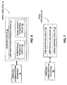
- Fig. 5 illustrates physical and/or logical circuit arrangements for a data sending unit 10 and a data receiving unit, in accordance with any one or more of the embodiments described above.
- the illustrated data receiving unit 12 comprises one or more processing circuits 14, one embodiment of which is detailed in Fig. 6 .
- a wireless communication interface 16 supports wireless communication with the wireless communication network 8, and includes various transmit and receive circuits, i.e., functions as a radiofrequency transceiver.
- the wireless communication interface 16 includes front-end receiver circuits which convert antenna-received signals into digital baseband samples that are input to a receiver circuit 20 for received signal processing, e.g., demodulation and decoding.
- the receiver circuit 20, which may be configured as a G-Rake receiver as discussed earlier herein, may comprise all or part of digital baseband processing circuit.
- Such a circuit may, as is known in the art, be implemented using one or more microprocessors, digital signal processors, FPGAs, ASICs, or other digital processing circuits.
- the functional logic of received signal processing may be embodied in hardware, software, or any combination thereof.
- the predictive link adaptation included in the STRR processing taught herein is embodied in a link adaptation feedback circuit 22, that is included in the receiver circuit 20, or that is associated with the receiver circuit 20.
- the link adaptation feedback circuit 22 may comprise hardware, software, or any combination thereof, and all or part of the processing logic associated with supporting predictive link adaptation may be embodied as computer program instructions held in a memory circuit included in or accessible to the link adaptation feedback circuit 22.
- an interference estimation circuit 24 and signal quality estimation circuit 26 represent logical circuit elements included in or associated with the link adaptation circuit 22.
- the interference estimation circuit 24 is configured, in one or more embodiments, to carry out impairment correlation estimations for a future transmit interval based on the corresponding transmit resource allocations signaled by one or more data sending units 10.
- the interference estimation circuit 24 may comprise part of G-Rake receiver processing carried out by the receiver circuit 20, and may implement Eq. (2) or Eq. (3).
- the interference contributions of surrounding data sending units 10 for a future transmit interval is or is not considered (or is weighted or otherwise adjusted), as a function of the corresponding future transmit resource allocations signaled by those data sending units 10.
- a signal quality estimation circuit 26 uses the corresponding interference estimation to compute a measure of signal quality for the future transmit interval.
- the data receiving unit 12 may return the signal quality estimate to its data supporting unit 10 as the link adaptation feedback, or it may map or otherwise translate the computed signal quality into a channel quality indicator, a data rate request, or other corresponding, possibly quantized value that is tied to the signal quality expected for the future transmit interval.
- an exemplary embodiment of the data sending unit 10 similarly includes one or more processing circuits 30, which, as shown in Fig. 7 , include a link adaptation circuit 32, a user scheduling circuit 34, and communication/control circuits 36.
- these processing and control circuits may be implemented or supported by logical circuit structures implemented within the data sending unit 10, using hardware, software, or any combination thereof.
- the link adaptation circuit 32 may be configured to support predictive link adaptation as taught herein by executing corresponding computer instructions on one or more microprocessors, digital signal processors, or other digital processing elements.
- the disadvantaged-user and fractional-resource loading aspects of predictive link adaptation may be incorporated into the operations of the user scheduling circuit 34 through appropriate hardware and/or software provisions.
- the communication/control circuits 36 which provide transmit/receive data processing may be implemented in hardware or software, and may communicate with the user scheduling and link adaptation circuits 34 and 32, respectively, such as for assistance in collecting incoming packet data to be transmitted to targeted data receiving units 12, and/or to for tracking packet data queue sizes.
- any or all such circuits may be communicatively coupled, directly or indirectly, to a wireless communication interface 38 that supports communication with the (remote) data receiving units 12.
- the data sending unit 10 is a radio base station and the wireless communication interface 38 includes radiofrequency transceiver circuits configured, for example, according to WCDMA air interface standards.
- the wireless communication network 8 may comprise a WCDMA network offering HSPDA services, or offering Orthogonal Frequency Division Multiplexing (OFDM) in accordance with developing "Super3G'or"Long Term Evolution” (LTE) and WiMAX standards.
- OFDM Orthogonal Frequency Division Multiplexing
- LTE Long Term Evolution
- WiMAX Worldwide Interoperability for Microwave Access
- the network 8 may be configured according to essentially any standard or air interface protocol, including WiMAX and any number of the developing "4G' wireless communication standards.
- the data sending units 10 and data receiving units 12 will be configured accordingly.
- a transmit interval may correspond to a frame.
- the data receiving units 12 comprises wireless communication devices configured for operation in a WiMAX or LTE wireless communication network.
- receiving indications of future transmit resource allocations to be used by one or more data sending units 10 in a future transmit interval may comprise receiving indications of future transmit resource allocations from one or more base stations in the WiMAX or LTE wireless communication network for a future Transmit Time Interval (TTI) or frame of a WiMAX or LTE air interface.
- TTI Transmit Time Interval
- a data sending unit 10 can be configured to 'listen' for announcements from data receiving units 12 in nearby cells or sectors announcing that they are about to send packet data. By tracking the power levels used by those data receiving units 12 to send packet data, the data sending unit 10 can compute a SINR (or other signal quality measurement), and adapt uplink data rates accordingly.
- SINR or other signal quality measurement
Landscapes
- Engineering & Computer Science (AREA)
- Computer Networks & Wireless Communication (AREA)
- Signal Processing (AREA)
- Mobile Radio Communication Systems (AREA)
Claims (29)
- Procédé d'adaptation de liaison dans un réseau de communication sans fil comprenant :la signalisation d'allocations de ressources d'émission futures pour un intervalle d'émission futur à partir d'une ou plusieurs unités d'envoi de données par l'émission d'informations d'allocation de ressources de canalisation correspondant à des allocations de ressources de canalisation à utiliser par une ou plusieurs unités d'envoi de données dans l'intervalle d'émission futur, de sorte que des unités de réception de données proches tiennent compte des allocations de ressources d'émission futures dans leurs déterminations basées sur interférences de rétroaction d'adaptation de liaison pour les intervalles d'émission futurs ;à une unité d'envoi de données donnée, la réception d'une rétroaction d'adaptation de liaison pour l'intervalle d'émission futur en provenance de l'une associée des unités de réception de données ; etdans l'intervalle d'émission futur, l'adaptation d'une liaison d'émission à l'unité d'envoi de données donnée pour l'unité de réception de données associée en fonction de la rétroaction d'adaptation de liaison.
- Procédé selon la revendication 1, dans lequel l'émission des informations d'allocation de ressources de canalisation comprend l'envoi d'informations identifiant des codes de canalisation ou des fréquences de canalisation à utiliser par une ou plusieurs unités d'envoi de données dans l'intervalle d'émission futur.
- Procédé selon la revendication 1, dans lequel l'émission des informations d'allocation de ressources de canalisation comprend l'envoi d'informations identifiant au moins l'un de débits de données d'émission et d'allocations de puissance d'émission à utiliser avec un ou plusieurs codes de canalisation ou fréquences de canalisation dans l'intervalle d'émission futur.
- Procédé selon la revendication 1, comprenant en outre, à une ou plusieurs des unités d'envoi de données, la détermination des allocations de ressources d'émission futures sur la base d'un objectif d'ordonnancement polarisé vers une amélioration de service à des unités de réception de données dans des conditions de réception défavorables.
- Procédé selon la revendication 1, comprenant en outre, à une ou plusieurs des unités d'envoi de données, la détermination des allocations de ressources d'émission futures sur la base d'une connaissance de conditions radio pour des unités de réception de données associées parmi les unités de réception de données qui sont candidates pour être desservies dans l'intervalle d'émission futur.
- Procédé selon la revendication 1, dans lequel l'adaptation de la liaison d'émission comprend l'émission de données de l'unité d'envoi de données donnée à l'unité de réception de données associée en utilisant un format basé sur la rétroaction d'adaptation de liaison.
- Procédé selon la revendication 1, comprenant en outre la signalisation des allocations de ressources d'émission futures en utilisant une puissance de signal supérieure à celle allouée à d'autres signaux de commande émis par l'unité d'envoi de données, en améliorant de ce fait une réception du signal pour les unités de réception de données à l'extérieur d'une réception de signalisation de commande fiable mais toujours soumises à des interférences provoquées par l'unité d'envoi de données.
- Procédé selon la revendication 1, dans lequel les unités d'envoi de données comprennent des stations de base radio configurées pour fonctionner dans un réseau de communication basé sur multiplexage par répartition de fréquence orthogonale (OFDM), et dans lequel la signalisation des allocations de ressources d'émission futures comprend l'émission d'informations identifiant au moins l'un des assignations de fréquences de sous-porteuses OFDM, des débits de données de sous-porteuses OFDM et des allocations de puissance de sous-porteuses OFDM.
- Unité d'envoi de données (10) destinée à être utilisée dans un réseau de communication sans fil, ladite unité d'envoi de données (10) comprenant un ou plusieurs circuits de traitement (30) configurés pour effectuer :la signalisation d'une allocation de ressources d'émission future pour un intervalle d'émission futur par l'émission d'informations d'allocation de ressources de canalisation correspondant à des allocations de ressources de canalisation à utiliser par une ou plusieurs unités d'envoi de données (10) dans l'intervalle d'émission futur, de sorte que des unités de réception de données proches (12) puissent tenir compte de l'allocation de ressources d'émission future dans leurs déterminations basées sur interférences de rétroaction d'adaptation de liaison pour l'intervalle d'émission futur ;la réception d'une rétroaction d'adaptation de liaison pour l'intervalle d'émission futur en provenance d'une unité de réception de données (12) associée ; etl'adaptation d'une unité de liaison d'émission pour l'unité de réception de données (12) associée dans l'intervalle d'émission futur en fonction de la rétroaction d'adaptation de liaison.
- Unité d'envoi de données selon la revendication 9, dans laquelle l'unité d'envoi de données comprend une station de base configurée pour fonctionner dans un réseau de communication sans fil WCDMA, WiMAX ou LTE, et dans laquelle l'unité d'envoi de données est configurée pour effectuer la signalisation des allocations de ressources d'émission futures pour un intervalle de temps d'émission, TTI, futur.
- Unité d'envoi de données (10) selon la revendication 9, dans laquelle l'unité d'envoi de données comprend en outre une interface de communication sans fil (38) configurée pour effectuer l'émission de signaux à des unités de réception de données (12) et la réception de signaux en provenance des unités d'envoi de données, et dans laquelle l'un ou plusieurs circuits de traitement comprennent un organe de commande d'ordonnancement configuré pour effectuer la détermination de l'allocation de ressources d'émission future pour l'intervalle d'émission futur et pour amener l'allocation de ressources d'émission future à être signalée par l'intermédiaire de 1"interface de communication sans fil, et un organe de commande d'adaptation de liaison configuré pour effectuer l'adaptation de la liaison d'émission pour l'unité de réception de données associée dans l'intervalle d'émission futur en fonction de la rétroaction d'adaptation de liaison.
- Unité d'envoi de données selon la revendication 9, dans laquelle l'un ou plusieurs circuits de traitement de l'unité d'envoi de données sont configurés pour effectuer l'émission des informations d'allocation de ressources de canalisation par l'envoi d'informations identifiant des codes de canalisation ou des fréquences de canalisation à utiliser par une ou plusieurs unités d'envoi de données dans l'intervalle d'émission futur.
- Unité d'envoi de données selon la revendication 9, dans laquelle l'un ou plusieurs circuits de traitement de l'unité d'envoi de données sont configurés pour effectuer l'émission des informations d'allocation de ressources de canalisation par l'envoi d'informations identifiant au moins l'un de débits de données d'émission et d'allocation de puissance d'émission à utiliser avec un ou plusieurs codes de canalisation ou fréquences de canalisation dans l'intervalle d'émission futur.
- Unité d'envoi de données selon la revendication 9, dans laquelle l'un ou plusieurs circuits de traitement de l'unité d'envoi de données sont configurés pour effectuer la détermination de l'allocation de ressources d'émission future sur la base d'un objectif d'ordonnancement polarisé vers une amélioration de service à des unités de réception de données dans des conditions de réception défavorables.
- Unité d'envoi de données selon la revendication 9, dans laquelle l'un ou plusieurs circuits de traitement de l'unité d'envoi de données sont configurés pour effectuer la détermination des allocations de ressources d'émission futures sur la base d'une connaissance de conditions radio pour des unités de réception de données associées qui sont candidates pour être desservies par l'unité d'envoi de données dans l'intervalle d'émission futur.
- Unité d'envoi de données selon la revendication 9, dans laquelle l'un ou plusieurs circuits de traitement de l'unité d'envoi de données sont configurés pour effectuer l'adaptation de l'unité de liaison d'émission par l'émission de données de l'unité d'envoi de données à l'unité de réception de données associée en utilisant un format basé sur la rétroaction d'adaptation de liaison.
- Unité d'envoi de données selon la revendication 9, dans laquelle l'unité d'envoi de données est configurée pour effectuer la signalisation de l'allocation de ressources d'émission future en utilisant une puissance de signal supérieure à celle allouée à d'autres signaux de commande émis par l'unité d'envoi de données, en améliorant de ce fait une réception du signal pour les unités de réception de données à l'extérieur de la réception de signalisation de commande fiable mais toujours soumises à des interférences provoquées par l'unité d'envoi de données.
- Unité d'envoi de données selon la revendication 9, dans laquelle l'unité d'envoi de données comprend une station de base radio configurée pour fonctionner dans un réseau de communication basé sur multiplexage par répartition de fréquence orthogonale (OFDM), et dans laquelle l'unité d'envoi de données est configurée pour effectuer la signalisation des allocations de ressources d'émission futures par l'émission d'informations identifiant au moins l'un des éléments suivants d'informations pour l'intervalle d'émission futur : des assignations de fréquences de sous-porteuses OFDM, des débits de données de sous-porteuses OFDM et des allocations de puissance de sous-porteuses OFDM.
- Procédé de prise en charge d'une adaptation de liaison destinée à être utilisée dans une unité de réception de données configurée pour fonctionner dans un réseau de communication sans fil comportant plusieurs unités d'envoi de données, le procédé comprenant :la réception d'indications d'allocations de ressources d'émission futures à utiliser par une ou plusieurs unités d'envoi de données dans un intervalle d'émission futur, lesdites indications comprenant des informations d'allocation de ressources de canalisation correspondant à des allocations de ressources de canalisation à utiliser par une ou plusieurs unités d'envoi de données dans l'intervalle d'émission futur ;la prédiction de conditions d'interférences pour l'intervalle d'émission futur sur la base des indications des allocations de ressources d'émission futures et la détermination d'une rétroaction d'adaptation de liaison pour l'intervalle d'émission futur sur la base des conditions d'interférences prédites ; etl'émission de la rétroaction d'adaptation de liaison pour l'intervalle d'émission futur à une unité d'envoi de données de prise en charge parmi les unités d'envoi de données.
- Procédé selon la revendication 19, dans lequel la détermination de la rétroaction d'adaptation de liaison pour l'intervalle d'émission futur comprend l'estimation d'une qualité de signal pour l'intervalle d'émission futur sur la base des conditions d'interférences prédites et la détermination, de manière correspondante, d'un débit de données maximal pouvant être pris en charge par l'unité de réception de données dans l'intervalle d'émission futur, et l'envoi d'une adaptation de rétroaction de liaison qui demande directement ou indirectement ce débit pour l'intervalle d'émission futur.
- Procédé selon la revendication 19, dans lequel la prédiction des conditions d'interférences pour l'intervalle d'émission futur comprend l'estimation de contributions d'interférences d'unités d'envoi de données individuelles sur la base des informations d'allocation de ressources de canalisation correspondantes.
- Procédé selon la revendication 21, dans lequel les informations d'allocation de ressources de canalisation comprennent au moins l'une d'allocations de codes de canalisation et d'allocations de fréquences de canalisation, et dans lequel l'estimation des contributions d'interférences d'unités d'envoi de données individuelles est basée sur une connaissance des allocations de codes de canalisation ou de fréquences de canalisation correspondantes.
- Procédé selon la revendication 19, dans lequel les unités d'envoi de données sont des stations de base basées sur multiplexage par répartition de fréquence orthogonale, OFDM, dans un réseau de communication OFDM, et dans lequel la réception des indications d'allocations de ressources d'émission futures comprend, pour au moins l'unité d'envoi de données, la réception d'informations identifiant au moins l'un d'assignations de fréquences de sous-porteuses OFDM, de débits de données de sous-porteuses OFDM et d'allocations de puissance de sous-porteuses OFDM.
- Unité de réception de données (12) configurée pour fonctionner dans un réseau de communication sans fil comportant un nombre d'unités d'envoi de données (10), l'unité de réception de données (12) comprenant un ou plusieurs circuits de traitement (14) configurés pour effectuer :la réception d'indications d'allocations de ressources d'émission futures à utiliser par une ou plusieurs unités d'envoi de données dans un intervalle d'émission futur, lesdites indications comprenant des informations d'allocation de ressources de canalisation correspondant à des allocations de ressources de canalisation à utiliser par une ou plusieurs unités d'envoi de données dans l'intervalle d'émission futur ;la prédiction de conditions d'interférences pour l'intervalle d'émission futur sur la base des indications d'allocations de ressources d'émission futures et la détermination d'une rétroaction d'adaptation de liaison pour l'intervalle d'émission futur sur la base des conditions d'interférences prédites ; etl'émission de la rétroaction d'adaptation de liaison pour l'intervalle d'émission futur à une unité d'envoi de données de prise en charge parmi les unités d'envoi de données.
- Unité de réception de données selon la revendication 24, dans laquelle l'un ou plusieurs circuits de traitement de l'unité de réception de données sont configurés pour effectuer la détermination de la rétroaction d'adaptation de liaison pour l'intervalle d'émission futur par l'estimation d'une qualité de signal pour l'intervalle d'émission futur sur la base des conditions d'interférences prédites et la détermination, de manière correspondante, d'un débit de données maximal pouvant être pris en charge par l'unité de réception de données dans l'intervalle d'émission futur, et l'envoi d'une adaptation de rétroaction de liaison qui demande directement ou indirectement ce débit pour l'intervalle d'émission futur.
- Unité de réception de données selon la revendication 24, dans laquelle l'un ou plusieurs circuits de traitement de l'unité de réception de données sont configurés pour effectuer la prédiction des conditions d'interférences pour l'intervalle d'émission futur par l'estimation de contributions d'interférences d'unités d'envoi de données individuelles sur la base des informations d'allocation de ressources de canalisation correspondantes.
- Unité de réception de données selon la revendication 26, dans laquelle les informations d'allocation de ressources de canalisation comprennent au moins l'une d'allocations de codes de canalisation et d'allocations de fréquences de canalisation, et dans laquelle l'un ou plusieurs circuits de traitement de l'unité de réception de données sont configurés pour effectuer l'estimation de la contribution d'interférences d'unités d'envoi de données individuelles sur la base d'une connaissance des allocations de codes de canalisation ou de fréquences de canalisation.
- Unité de réception de données selon la revendication 24, dans laquelle l'unité de réception de données comprend un dispositif de communication sans fil configuré pour fonctionner dans un réseau de communication sans fil WCDMA, WiMAX ou LTE, et dans laquelle l'unité de réception de données est configurée pour effectuer la réception des indications d'allocations de ressources d'émission futures en tant qu'indications d'allocations de ressources d'émission futures en provenance d'une ou plusieurs stations de base dans le réseau de communication sans fil, pour un intervalle de temps d'émission, TTI, futur.
- Unité de réception de données selon la revendication 24, dans laquelle les unités d'envoi de données sont des stations de base basées sur multiplexage par répartition de fréquence orthogonale, OFDM, dans un réseau de communication OFDM, et dans laquelle l'unité de réception de données est configurée pour effectuer la réception des indications d'allocations de ressources d'émission futures par, pour au moins l'unité d'envoi de données, la réception d'informations identifiant au moins l'un d'assignations de fréquences de sous-porteuses OFDM, de débits de données de sous-porteuses OFDM et d'allocations de puissance de sous-porteuses OFDM.
Priority Applications (3)
| Application Number | Priority Date | Filing Date | Title |
|---|---|---|---|
| PL16194907T PL3142394T3 (pl) | 2007-03-02 | 2007-04-12 | Sposób i urządzenie do ponownego użycia zasobów w systemie komunikacyjnym |
| EP16194907.8A EP3142394B1 (fr) | 2007-03-02 | 2007-04-12 | Procédé et appareil pour la réutilisation de ressources dans un système de communication |
| DK16194907.8T DK3142394T3 (da) | 2007-03-02 | 2007-04-12 | Fremgangsmåde og indretning til ressourcegenanvendelse i et kommunikationssystem |
Applications Claiming Priority (2)
| Application Number | Priority Date | Filing Date | Title |
|---|---|---|---|
| US11/681,302 US7899015B2 (en) | 2007-03-02 | 2007-03-02 | Method and apparatus for resource reuse in a communication system |
| PCT/SE2007/050236 WO2008108698A1 (fr) | 2007-03-02 | 2007-04-12 | Procédé et appareil pour une réutilisation de ressources dans un système de communication |
Related Child Applications (1)
| Application Number | Title | Priority Date | Filing Date |
|---|---|---|---|
| EP16194907.8A Division EP3142394B1 (fr) | 2007-03-02 | 2007-04-12 | Procédé et appareil pour la réutilisation de ressources dans un système de communication |
Publications (3)
| Publication Number | Publication Date |
|---|---|
| EP2119079A1 EP2119079A1 (fr) | 2009-11-18 |
| EP2119079A4 EP2119079A4 (fr) | 2013-01-16 |
| EP2119079B1 true EP2119079B1 (fr) | 2016-11-09 |
Family
ID=39732998
Family Applications (2)
| Application Number | Title | Priority Date | Filing Date |
|---|---|---|---|
| EP16194907.8A Active EP3142394B1 (fr) | 2007-03-02 | 2007-04-12 | Procédé et appareil pour la réutilisation de ressources dans un système de communication |
| EP07748397.2A Active EP2119079B1 (fr) | 2007-03-02 | 2007-04-12 | Procédé et appareil pour une réutilisation de ressources dans un système de communication |
Family Applications Before (1)
| Application Number | Title | Priority Date | Filing Date |
|---|---|---|---|
| EP16194907.8A Active EP3142394B1 (fr) | 2007-03-02 | 2007-04-12 | Procédé et appareil pour la réutilisation de ressources dans un système de communication |
Country Status (9)
| Country | Link |
|---|---|
| US (1) | US7899015B2 (fr) |
| EP (2) | EP3142394B1 (fr) |
| JP (1) | JP5038441B2 (fr) |
| DK (2) | DK3142394T3 (fr) |
| ES (2) | ES2614637T3 (fr) |
| HU (1) | HUE031574T2 (fr) |
| PL (1) | PL3142394T3 (fr) |
| PT (1) | PT2119079T (fr) |
| WO (1) | WO2008108698A1 (fr) |
Families Citing this family (23)
| Publication number | Priority date | Publication date | Assignee | Title |
|---|---|---|---|---|
| US8031798B2 (en) * | 2007-03-13 | 2011-10-04 | Nec Laboratories America, Inc. | Group MMSE-DFD with rate (SINR) feedback and pre-determined decoding order for reception on a cellular downlink |
| WO2008112862A1 (fr) * | 2007-03-13 | 2008-09-18 | Nec Laboratories America, Inc. | Démodulation lmmse de groupe utilisant une matrice de covariance de bruit et d'interférence pour réception sur une liaison descendante cellulaire |
| US8325621B2 (en) * | 2007-04-20 | 2012-12-04 | Telefonaktiebolaget Lm Ericsson (Publ) | Inter-cell interference co-ordination |
| JP5016109B2 (ja) * | 2007-06-18 | 2012-09-05 | ノキア コーポレイション | タイミングアライメントを提供するための方法および装置 |
| EP2194738B1 (fr) * | 2007-09-26 | 2021-05-26 | Denso Corporation | Système de communication sans fil, appareil de station de base et appareil de station mobile |
| JP2009188902A (ja) * | 2008-02-08 | 2009-08-20 | Nec Corp | 無線スケジューリング装置、無線通信システム、および無線スケジューリング方法 |
| US8767541B2 (en) * | 2008-02-14 | 2014-07-01 | Qualcomm Incorporated | Scheduling policy-based traffic management |
| US8737314B2 (en) | 2008-02-14 | 2014-05-27 | Qualcomm Incorporated | Traffic management for multi-hop wireless communication |
| US8964651B2 (en) * | 2008-02-14 | 2015-02-24 | Qualcomm Incorporated | Traffic management employing interference management messages |
| US8958371B2 (en) * | 2008-09-12 | 2015-02-17 | Qualcomm Incorporated | Interference management for different wireless communication technologies |
| US20100195586A1 (en) * | 2009-02-05 | 2010-08-05 | Infineon Technologies Ag | Multiband-operation in wireless communication systems |
| JP2010193197A (ja) * | 2009-02-18 | 2010-09-02 | Ntt Docomo Inc | 移動通信端末およびその制御方法 |
| EP2237591A1 (fr) * | 2009-04-03 | 2010-10-06 | Thomson Licensing, Inc. | Dispositif et procédé pour le calcul en ligne de régions de taux possibles dans un réseau d'accès aléatoire |
| US8369793B2 (en) * | 2009-10-02 | 2013-02-05 | Telefonaktiebolaget L M Ericsson (Publ) | Channel-dependent scheduling and link adaptation |
| CN102056220B (zh) | 2009-10-28 | 2014-02-19 | 华为技术有限公司 | 实现信道测量的方法及装置 |
| US8554235B2 (en) | 2010-11-11 | 2013-10-08 | Telefonaktiebolaget L M Ericcson (Publ) | Distributed scheduling coordination for plural service areas |
| US8401562B2 (en) * | 2010-11-17 | 2013-03-19 | Nokia Corporation | Apparatus and method employing scheduler behavior aware predictive resource selection in a communication system |
| KR20150038671A (ko) * | 2010-12-02 | 2015-04-08 | 인터디지탈 패튼 홀딩스, 인크 | 간섭 예측을 사용하여 무선 통신에서 채널 품질 표시 피드백 정확도를 향상시키는 시스템 및 방법 |
| US8699340B2 (en) | 2012-06-01 | 2014-04-15 | Telefonaktiebolaget L M Ericsson (Publ) | Table-based link adaptation for wireless communication network transmissions |
| EP2912872A4 (fr) * | 2012-10-26 | 2016-10-26 | Nokia Solutions & Networks Oy | Coordination de programmation |
| WO2017168364A1 (fr) * | 2016-04-01 | 2017-10-05 | Telefonaktiebolaget Lm Ericsson (Publ) | Procédé pour programmer des communications de véhicule à véhicule |
| WO2020206304A1 (fr) * | 2019-04-04 | 2020-10-08 | Cohere Technologies, Inc. | Fonctionnement de réseau multipoint coopératif massif |
| WO2023009041A1 (fr) * | 2021-07-27 | 2023-02-02 | Telefonaktiebolaget Lm Ericsson (Publ) | Procédé et nœud de réseau pour la planification d'une communication radio en fonction de profils de trafic d'équipements utilisateurs |
Family Cites Families (20)
| Publication number | Priority date | Publication date | Assignee | Title |
|---|---|---|---|---|
| SE521227C2 (sv) * | 1999-02-22 | 2003-10-14 | Ericsson Telefon Ab L M | Mobilradiosystem och ett förfarande för kanallokering i ett mobilradiosystem |
| US6497599B1 (en) * | 1999-03-01 | 2002-12-24 | Nortel Networks Limited | Channel reuse patterns in a mobile communications system |
| SE0001918L (sv) | 2000-05-23 | 2001-11-24 | Ericsson Telefon Ab L M | Aktivitetsindikerande pilot |
| US7072315B1 (en) * | 2000-10-10 | 2006-07-04 | Adaptix, Inc. | Medium access control for orthogonal frequency-division multiple-access (OFDMA) cellular networks |
| US7046644B1 (en) * | 2000-11-27 | 2006-05-16 | Nokia Mobile Phones Ltd. | Adaptive transmission channel allocation method and system for ISM and unlicensed frequency bands |
| MXPA04012800A (es) * | 2002-07-03 | 2005-03-31 | Siemens Ag | Procedimiento para controlar la transmision de datos en un sistema de comunicacion por radio con arquitectura de red jerarquica. |
| KR100988536B1 (ko) | 2002-11-01 | 2010-10-20 | 인터디지탈 테크날러지 코포레이션 | 무선 통신 시스템용 채널 품질 예측 방법 |
| US7548531B2 (en) | 2002-12-16 | 2009-06-16 | Avaya Inc. | Poll scheduling for periodic traffic sources |
| US20040120289A1 (en) * | 2002-12-20 | 2004-06-24 | Hamalainen Jyri K. | Transmission of information in a wireless communication system |
| KR20050038977A (ko) * | 2003-10-23 | 2005-04-29 | 삼성전자주식회사 | 무선 통신 시스템에서 자원 할당 정보 송수신 시스템 및방법 |
| US7738534B2 (en) * | 2003-11-24 | 2010-06-15 | Telefonaktiebolaget Lm Ericsson (Publ) | Multi-transmitter interference suppression using code-specific combining |
| US7539240B2 (en) * | 2004-03-12 | 2009-05-26 | Telefonaftiebolaget Lm Ericsson (Publ) | Method and apparatus for parameter estimation in a generalized rake receiver |
| GB2418102B (en) | 2004-06-16 | 2006-08-16 | Siemens Ag | A method of allocating uplink resources |
| US7376192B2 (en) * | 2004-07-22 | 2008-05-20 | Telefonaktiebolaget L M Ericsson (Publ) | Delta modulation for channel feedback in transmit diversity wireless communication systems |
| US7697948B2 (en) * | 2004-10-29 | 2010-04-13 | Telefonaktiebolaget L M Ericsson (Publ) | Resource allocation in communication networks |
| KR20070108304A (ko) * | 2005-10-31 | 2007-11-09 | 삼성전자주식회사 | 다중 송수신 안테나 시스템에서의 채널 품질 정보 송수신방법 및 장치 |
| KR101075777B1 (ko) * | 2006-02-14 | 2011-10-24 | 한국과학기술원 | 무선 통신 시스템에서 자원 할당 정보 송수신 시스템 및방법 |
| KR101493669B1 (ko) | 2006-03-20 | 2015-02-16 | 코닌클리케 필립스 엔.브이. | 신호 품질 보고 |
| US7894820B2 (en) * | 2006-05-01 | 2011-02-22 | Intel Corporation | Channel feedback using channel state predictions based also on delays |
| WO2008028507A1 (fr) * | 2006-09-06 | 2008-03-13 | Telefonaktiebolaget Lm Ericsson (Publ) | Programmation et adaptation de liaison dans des systèmes de télécommunications sans fil |
-
2007
- 2007-03-02 US US11/681,302 patent/US7899015B2/en active Active
- 2007-04-12 WO PCT/SE2007/050236 patent/WO2008108698A1/fr not_active Ceased
- 2007-04-12 HU HUE07748397A patent/HUE031574T2/en unknown
- 2007-04-12 JP JP2009551650A patent/JP5038441B2/ja active Active
- 2007-04-12 DK DK16194907.8T patent/DK3142394T3/da active
- 2007-04-12 DK DK07748397.2T patent/DK2119079T3/en active
- 2007-04-12 ES ES07748397.2T patent/ES2614637T3/es active Active
- 2007-04-12 EP EP16194907.8A patent/EP3142394B1/fr active Active
- 2007-04-12 ES ES16194907T patent/ES2784928T3/es active Active
- 2007-04-12 PL PL16194907T patent/PL3142394T3/pl unknown
- 2007-04-12 PT PT77483972T patent/PT2119079T/pt unknown
- 2007-04-12 EP EP07748397.2A patent/EP2119079B1/fr active Active
Non-Patent Citations (1)
| Title |
|---|
| None * |
Also Published As
| Publication number | Publication date |
|---|---|
| DK2119079T3 (en) | 2017-02-06 |
| ES2614637T3 (es) | 2017-06-01 |
| HUE031574T2 (en) | 2017-07-28 |
| US20080212539A1 (en) | 2008-09-04 |
| EP2119079A4 (fr) | 2013-01-16 |
| EP2119079A1 (fr) | 2009-11-18 |
| JP2010520659A (ja) | 2010-06-10 |
| US7899015B2 (en) | 2011-03-01 |
| ES2784928T3 (es) | 2020-10-02 |
| PL3142394T3 (pl) | 2020-07-27 |
| DK3142394T3 (da) | 2020-05-04 |
| EP3142394A1 (fr) | 2017-03-15 |
| WO2008108698A1 (fr) | 2008-09-12 |
| JP5038441B2 (ja) | 2012-10-03 |
| EP3142394B1 (fr) | 2020-02-19 |
| PT2119079T (pt) | 2017-01-18 |
Similar Documents
| Publication | Publication Date | Title |
|---|---|---|
| EP2119079B1 (fr) | Procédé et appareil pour une réutilisation de ressources dans un système de communication | |
| KR100955635B1 (ko) | 적응 변조 및 코딩 기법을 위한 공통 제어 채널 업링크 전력 제어 | |
| EP2013998B1 (fr) | Procede et appareil de commande de planification localisee et distribuee | |
| US7860056B2 (en) | Apparatus and method for allocating sub-channel in a wireless communication system | |
| US8654712B2 (en) | OFDMA reverse link scheduling | |
| US8259603B2 (en) | Cellular system, communication path quality measuring method, base station, and mobile station | |
| US8600396B2 (en) | Radio scheduling apparatus, radio communication system, and radio scheduling method | |
| TW200810410A (en) | Base station, user device and method used in mobile communication system | |
| AU2007351630A1 (en) | Method and arrangements for scheduling transmission resources with variable guard intervals | |
| RU2421920C2 (ru) | Надежный запрос ресурсов восходящей линии связи | |
| EP2068466B1 (fr) | Dispositif de station de base | |
| US8842625B2 (en) | Wireless scheduling considering overhead cost estimate | |
| US20070274263A1 (en) | Slot allocation method for use in cellular radio communication system and base station for use in the same system | |
| EP3297376B1 (fr) | Attribution de ressources pour une nouvelle estimation du lien radioélectrique en fonction de la validité de l'estimation actuelle | |
| JP2006074492A (ja) | 基地局装置、通信端末装置及びリソース割り当て方法 | |
| JP2003309875A (ja) | 移動通信システム、無線制御局、基地局、移動局および移動通信システムにおける無線リソースの割当制御方法 | |
| CN102047733B (zh) | 无线中继网络中用于测距的方法和装置 | |
| KR20070112214A (ko) | 부호계열 송신 방법, 무선 통신 시스템, 송신기 및 수신기 | |
| KR100801289B1 (ko) | 직교 주파수 분할 다중 접속 시스템의 상향링크 자원할당을위한 스케줄링 방법 및 장치 | |
| GB2413243A (en) | Method of enhancing uplink transmissions |
Legal Events
| Date | Code | Title | Description |
|---|---|---|---|
| PUAI | Public reference made under article 153(3) epc to a published international application that has entered the european phase |
Free format text: ORIGINAL CODE: 0009012 |
|
| 17P | Request for examination filed |
Effective date: 20090903 |
|
| AK | Designated contracting states |
Kind code of ref document: A1 Designated state(s): AT BE BG CH CY CZ DE DK EE ES FI FR GB GR HU IE IS IT LI LT LU LV MC MT NL PL PT RO SE SI SK TR |
|
| DAX | Request for extension of the european patent (deleted) | ||
| REG | Reference to a national code |
Ref country code: DE Ref legal event code: R079 Ref document number: 602007048652 Country of ref document: DE Free format text: PREVIOUS MAIN CLASS: H04L0001000000 Ipc: H04W0004180000 |
|
| A4 | Supplementary search report drawn up and despatched |
Effective date: 20121213 |
|
| RIC1 | Information provided on ipc code assigned before grant |
Ipc: H04W 4/18 20090101AFI20121207BHEP |
|
| GRAP | Despatch of communication of intention to grant a patent |
Free format text: ORIGINAL CODE: EPIDOSNIGR1 |
|
| INTG | Intention to grant announced |
Effective date: 20160426 |
|
| GRAJ | Information related to disapproval of communication of intention to grant by the applicant or resumption of examination proceedings by the epo deleted |
Free format text: ORIGINAL CODE: EPIDOSDIGR1 |
|
| GRAL | Information related to payment of fee for publishing/printing deleted |
Free format text: ORIGINAL CODE: EPIDOSDIGR3 |
|
| GRAS | Grant fee paid |
Free format text: ORIGINAL CODE: EPIDOSNIGR3 |
|
| GRAR | Information related to intention to grant a patent recorded |
Free format text: ORIGINAL CODE: EPIDOSNIGR71 |
|
| GRAJ | Information related to disapproval of communication of intention to grant by the applicant or resumption of examination proceedings by the epo deleted |
Free format text: ORIGINAL CODE: EPIDOSDIGR1 |
|
| GRAR | Information related to intention to grant a patent recorded |
Free format text: ORIGINAL CODE: EPIDOSNIGR71 |
|
| GRAA | (expected) grant |
Free format text: ORIGINAL CODE: 0009210 |
|
| INTC | Intention to grant announced (deleted) | ||
| INTG | Intention to grant announced |
Effective date: 20160919 |
|
| INTG | Intention to grant announced |
Effective date: 20160928 |
|
| AK | Designated contracting states |
Kind code of ref document: B1 Designated state(s): AT BE BG CH CY CZ DE DK EE ES FI FR GB GR HU IE IS IT LI LT LU LV MC MT NL PL PT RO SE SI SK TR |
|
| REG | Reference to a national code |
Ref country code: GB Ref legal event code: FG4D |
|
| REG | Reference to a national code |
Ref country code: AT Ref legal event code: REF Ref document number: 844885 Country of ref document: AT Kind code of ref document: T Effective date: 20161115 Ref country code: CH Ref legal event code: EP |
|
| REG | Reference to a national code |
Ref country code: IE Ref legal event code: FG4D |
|
| REG | Reference to a national code |
Ref country code: DE Ref legal event code: R096 Ref document number: 602007048652 Country of ref document: DE |
|
| REG | Reference to a national code |
Ref country code: NL Ref legal event code: FP Ref country code: PT Ref legal event code: SC4A Ref document number: 2119079 Country of ref document: PT Date of ref document: 20170118 Kind code of ref document: T Free format text: AVAILABILITY OF NATIONAL TRANSLATION Effective date: 20170109 |
|
| REG | Reference to a national code |
Ref country code: DK Ref legal event code: T3 Effective date: 20170131 |
|
| PG25 | Lapsed in a contracting state [announced via postgrant information from national office to epo] |
Ref country code: LV Free format text: LAPSE BECAUSE OF FAILURE TO SUBMIT A TRANSLATION OF THE DESCRIPTION OR TO PAY THE FEE WITHIN THE PRESCRIBED TIME-LIMIT Effective date: 20161109 |
|
| REG | Reference to a national code |
Ref country code: LT Ref legal event code: MG4D |
|
| REG | Reference to a national code |
Ref country code: AT Ref legal event code: MK05 Ref document number: 844885 Country of ref document: AT Kind code of ref document: T Effective date: 20161109 |
|
| REG | Reference to a national code |
Ref country code: FR Ref legal event code: PLFP Year of fee payment: 11 |
|
| PG25 | Lapsed in a contracting state [announced via postgrant information from national office to epo] |
Ref country code: LT Free format text: LAPSE BECAUSE OF FAILURE TO SUBMIT A TRANSLATION OF THE DESCRIPTION OR TO PAY THE FEE WITHIN THE PRESCRIBED TIME-LIMIT Effective date: 20161109 Ref country code: SE Free format text: LAPSE BECAUSE OF FAILURE TO SUBMIT A TRANSLATION OF THE DESCRIPTION OR TO PAY THE FEE WITHIN THE PRESCRIBED TIME-LIMIT Effective date: 20161109 Ref country code: GR Free format text: LAPSE BECAUSE OF FAILURE TO SUBMIT A TRANSLATION OF THE DESCRIPTION OR TO PAY THE FEE WITHIN THE PRESCRIBED TIME-LIMIT Effective date: 20170210 |
|
| PG25 | Lapsed in a contracting state [announced via postgrant information from national office to epo] |
Ref country code: FI Free format text: LAPSE BECAUSE OF FAILURE TO SUBMIT A TRANSLATION OF THE DESCRIPTION OR TO PAY THE FEE WITHIN THE PRESCRIBED TIME-LIMIT Effective date: 20161109 Ref country code: PL Free format text: LAPSE BECAUSE OF FAILURE TO SUBMIT A TRANSLATION OF THE DESCRIPTION OR TO PAY THE FEE WITHIN THE PRESCRIBED TIME-LIMIT Effective date: 20161109 Ref country code: IS Free format text: LAPSE BECAUSE OF FAILURE TO SUBMIT A TRANSLATION OF THE DESCRIPTION OR TO PAY THE FEE WITHIN THE PRESCRIBED TIME-LIMIT Effective date: 20170309 Ref country code: AT Free format text: LAPSE BECAUSE OF FAILURE TO SUBMIT A TRANSLATION OF THE DESCRIPTION OR TO PAY THE FEE WITHIN THE PRESCRIBED TIME-LIMIT Effective date: 20161109 |
|
| REG | Reference to a national code |
Ref country code: ES Ref legal event code: FG2A Ref document number: 2614637 Country of ref document: ES Kind code of ref document: T3 Effective date: 20170601 |
|
| REG | Reference to a national code |
Ref country code: HU Ref legal event code: AG4A Ref document number: E031574 Country of ref document: HU |
|
| PG25 | Lapsed in a contracting state [announced via postgrant information from national office to epo] |
Ref country code: EE Free format text: LAPSE BECAUSE OF FAILURE TO SUBMIT A TRANSLATION OF THE DESCRIPTION OR TO PAY THE FEE WITHIN THE PRESCRIBED TIME-LIMIT Effective date: 20161109 Ref country code: RO Free format text: LAPSE BECAUSE OF FAILURE TO SUBMIT A TRANSLATION OF THE DESCRIPTION OR TO PAY THE FEE WITHIN THE PRESCRIBED TIME-LIMIT Effective date: 20161109 Ref country code: SK Free format text: LAPSE BECAUSE OF FAILURE TO SUBMIT A TRANSLATION OF THE DESCRIPTION OR TO PAY THE FEE WITHIN THE PRESCRIBED TIME-LIMIT Effective date: 20161109 |
|
| REG | Reference to a national code |
Ref country code: DE Ref legal event code: R097 Ref document number: 602007048652 Country of ref document: DE |
|
| PG25 | Lapsed in a contracting state [announced via postgrant information from national office to epo] |
Ref country code: BG Free format text: LAPSE BECAUSE OF FAILURE TO SUBMIT A TRANSLATION OF THE DESCRIPTION OR TO PAY THE FEE WITHIN THE PRESCRIBED TIME-LIMIT Effective date: 20170209 Ref country code: BE Free format text: LAPSE BECAUSE OF FAILURE TO SUBMIT A TRANSLATION OF THE DESCRIPTION OR TO PAY THE FEE WITHIN THE PRESCRIBED TIME-LIMIT Effective date: 20161109 |
|
| PLBE | No opposition filed within time limit |
Free format text: ORIGINAL CODE: 0009261 |
|
| STAA | Information on the status of an ep patent application or granted ep patent |
Free format text: STATUS: NO OPPOSITION FILED WITHIN TIME LIMIT |
|
| 26N | No opposition filed |
Effective date: 20170810 |
|
| PG25 | Lapsed in a contracting state [announced via postgrant information from national office to epo] |
Ref country code: SI Free format text: LAPSE BECAUSE OF FAILURE TO SUBMIT A TRANSLATION OF THE DESCRIPTION OR TO PAY THE FEE WITHIN THE PRESCRIBED TIME-LIMIT Effective date: 20161109 |
|
| REG | Reference to a national code |
Ref country code: CH Ref legal event code: PL |
|
| PG25 | Lapsed in a contracting state [announced via postgrant information from national office to epo] |
Ref country code: MC Free format text: LAPSE BECAUSE OF FAILURE TO SUBMIT A TRANSLATION OF THE DESCRIPTION OR TO PAY THE FEE WITHIN THE PRESCRIBED TIME-LIMIT Effective date: 20161109 |
|
| PG25 | Lapsed in a contracting state [announced via postgrant information from national office to epo] |
Ref country code: LI Free format text: LAPSE BECAUSE OF NON-PAYMENT OF DUE FEES Effective date: 20170430 Ref country code: LU Free format text: LAPSE BECAUSE OF NON-PAYMENT OF DUE FEES Effective date: 20170412 Ref country code: CH Free format text: LAPSE BECAUSE OF NON-PAYMENT OF DUE FEES Effective date: 20170430 |
|
| REG | Reference to a national code |
Ref country code: FR Ref legal event code: PLFP Year of fee payment: 12 |
|
| PG25 | Lapsed in a contracting state [announced via postgrant information from national office to epo] |
Ref country code: MT Free format text: LAPSE BECAUSE OF NON-PAYMENT OF DUE FEES Effective date: 20170412 |
|
| PG25 | Lapsed in a contracting state [announced via postgrant information from national office to epo] |
Ref country code: CY Free format text: LAPSE BECAUSE OF NON-PAYMENT OF DUE FEES Effective date: 20161109 |
|
| P01 | Opt-out of the competence of the unified patent court (upc) registered |
Effective date: 20230523 |
|
| PGFP | Annual fee paid to national office [announced via postgrant information from national office to epo] |
Ref country code: NL Payment date: 20250427 Year of fee payment: 19 |
|
| PGFP | Annual fee paid to national office [announced via postgrant information from national office to epo] |
Ref country code: DE Payment date: 20250429 Year of fee payment: 19 |
|
| PGFP | Annual fee paid to national office [announced via postgrant information from national office to epo] |
Ref country code: GB Payment date: 20250428 Year of fee payment: 19 Ref country code: ES Payment date: 20250505 Year of fee payment: 19 Ref country code: DK Payment date: 20250425 Year of fee payment: 19 |
|
| PGFP | Annual fee paid to national office [announced via postgrant information from national office to epo] |
Ref country code: HU Payment date: 20250326 Year of fee payment: 19 |
|
| PGFP | Annual fee paid to national office [announced via postgrant information from national office to epo] |
Ref country code: IT Payment date: 20250422 Year of fee payment: 19 |
|
| PGFP | Annual fee paid to national office [announced via postgrant information from national office to epo] |
Ref country code: FR Payment date: 20250425 Year of fee payment: 19 |
|
| PGFP | Annual fee paid to national office [announced via postgrant information from national office to epo] |
Ref country code: IE Payment date: 20250428 Year of fee payment: 19 |
|
| PGFP | Annual fee paid to national office [announced via postgrant information from national office to epo] |
Ref country code: TR Payment date: 20260325 Year of fee payment: 20 |
|
| PGFP | Annual fee paid to national office [announced via postgrant information from national office to epo] |
Ref country code: PT Payment date: 20260323 Year of fee payment: 20 Ref country code: CZ Payment date: 20260324 Year of fee payment: 20 |