EP2119978A1 - Kühl- und/oder Heizgeräte, insbesondere Wärmepumpe, mit einer Halterung für ein flüssigkeitsführendes Rohr - Google Patents
Kühl- und/oder Heizgeräte, insbesondere Wärmepumpe, mit einer Halterung für ein flüssigkeitsführendes Rohr Download PDFInfo
- Publication number
- EP2119978A1 EP2119978A1 EP09006220A EP09006220A EP2119978A1 EP 2119978 A1 EP2119978 A1 EP 2119978A1 EP 09006220 A EP09006220 A EP 09006220A EP 09006220 A EP09006220 A EP 09006220A EP 2119978 A1 EP2119978 A1 EP 2119978A1
- Authority
- EP
- European Patent Office
- Prior art keywords
- cooling
- wall
- heating device
- holder
- pipe
- Prior art date
- Legal status (The legal status is an assumption and is not a legal conclusion. Google has not performed a legal analysis and makes no representation as to the accuracy of the status listed.)
- Granted
Links
Images
Classifications
-
- F—MECHANICAL ENGINEERING; LIGHTING; HEATING; WEAPONS; BLASTING
- F24—HEATING; RANGES; VENTILATING
- F24F—AIR-CONDITIONING; AIR-HUMIDIFICATION; VENTILATION; USE OF AIR CURRENTS FOR SCREENING
- F24F13/00—Details common to, or for air-conditioning, air-humidification, ventilation or use of air currents for screening
- F24F13/20—Casings or covers
-
- F—MECHANICAL ENGINEERING; LIGHTING; HEATING; WEAPONS; BLASTING
- F24—HEATING; RANGES; VENTILATING
- F24F—AIR-CONDITIONING; AIR-HUMIDIFICATION; VENTILATION; USE OF AIR CURRENTS FOR SCREENING
- F24F13/00—Details common to, or for air-conditioning, air-humidification, ventilation or use of air currents for screening
- F24F13/32—Supports for air-conditioning, air-humidification or ventilation units
Definitions
- the invention relates to a cooling and / or heating device, in particular a heat pump, with a holder for a liquid-carrying pipe, which is flowed through by heated or cooled liquid and is guided through an opening in a wall of the cooling and / or heating device.
- a part of a heat pump is selected as an exemplary embodiment, in which pipes are located, which are led out of the heat pump.
- Cooling and / or heating devices in particular heat pumps, have in the interior a refrigerant circuit with which heat and / or cold is generated.
- heat pumps which heat and / or cool a liquid
- the energy is delivered by means of a fluid via pipes to a heating, cooling or hot water system.
- the pipes are passed through a wall of the heat pump.
- there is a generous opening in the wall which is much larger than the outer diameter of the pipes.
- the openings can compensate for misalignment or play in the piping.
- the pipes do not touch the walls.
- Also known in the market are pipe ducts in which the raw leads are routed through the wall and are connected to it via the pipe duct.
- the heat and / or cooling release preferably takes place via heating or cooling body, in the pipes are led, which carry the fluid.
- the object of the invention is to guide a liquid-carrying pipe of a heat pump through a wall, in particular housing wall of the heat pump, and at the same time to attach to the wall, wherein the heat conduction between the pipe and wall should be as low as possible.
- a liquid-conducting tube is located in a holder and is held in a plane which has a distance to a wall, in particular a housing wall of a cooling or heating device, in the embodiment of a heat pump in which there is an opening.
- the distance which is preferably greater than the wall thickness of the wall, in particular greater than a wall thickness of about 1 mm of a sheet of the wall.
- heat conduction from the pipe to the wall and the housing is avoided.
- a heat dissipation between pipe and wall is achieved and the tube is connected to the wall at the same time.
- This is particularly important when using heat pumps, e.g. In the reverse operation of a refrigerant circuit of the heat pump is generated cold and thus a heat transfer medium is guided through the pipelines, e.g. Cooling water for cooling, which has a lower temperature than the ambient air, in particular a temperature below the dew point of the ambient temperature.
- Cooling water for cooling which has a lower temperature than the ambient air, in particular a temperature below the dew point of the ambient temperature.
- the distance is greater than about half of a pipe diameter, in particular greater than about 10 mm. It is also advantageous if the holder consists at least partially of a plastic, in particular if the holder is made of plastic in the region of the distance. In the holder a seal is inserted. According to a further exemplary embodiment, in the case of a holder made of plastic, the seal is injection-molded onto the holder in a two-component injection molding process.
- Structure-borne noise in particular vibrations that are transmitted from the compressor to the tubes, can only extend to the housing parts in a highly damped manner.
- the damping is also achieved by the seal, in particular, if this is performed elastic.
- the bracket can achieve IP68 protection, which prevents dust or pressurized water from entering the heat pump.
- the cooling and / or heating device thus achieves at least degree of protection IP44 in one exemplary embodiment.
- the holder is also used in heating and cooling bodies, which constitute a heating and / or cooling device in the context of the invention.
- the heating and cooling bodies are supplied through pipes with a cooled or heated fluid and the space is heated or cooled. With the holder, these pipes are preferably held in a housing or frame of the heating and cooling body.
- a tube is thus thermally insulated with the holder into a wall of a heating and / or cooling device, wherein a fluid, which is cooled or heated, flows through the tube.
- a fluid which is cooled or heated
- the fluid is pumped by a pump either through the heating flow or the hot water supply.
- a brine pipe is led into the heat pump and out again.
- This brine is directed into an evaporator of the heat pump and releases energy there.
- brine flows at a temperature above or below this ambient temperature through the brine line.
- the brine flowing out of the heat pump was cooled in the evaporator.
- the brine line is advantageously in and out of a holder in the heat pump.
- the invention is also applicable to electric heaters, such as instantaneous water heaters or the like. applicable, in which a cold and a Warrrwassertechnisch or a supply and return line is guided.
- a heat pump having a housing, in at least partially a refrigerant circuit is located.
- the refrigerant circuit not shown, consists of a condenser, which is designed as a heat exchanger, or which is advantageously in a container which serves as a buffer memory and is provided with insulation, is arranged, a compressor and a liquid collector.
- a condenser which is designed as a heat exchanger, or which is advantageously in a container which serves as a buffer memory and is provided with insulation, is arranged, a compressor and a liquid collector.
- the heat pump according to the exemplary embodiment is an air-water heat pump in which a non-illustrated evaporator of the refrigerant circuit is located above a condensate tray and is applied in an advantageous manner to a Abtaublech.
- Condensate is led into the condensate sump via the defrosting plate and from there via a condensate drain out of the heat pump. Furthermore, not shown is an expansion vessel, a fan for the supply of outside air to the evaporator, and air ducting systems and a controller. Pipes for a hot water supply and return as well as for a heating supply and return are connected to the container or heat exchanger.
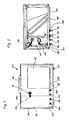
- Fig. 1 shows a portion of a heat pump 100 from the rear, where through a wall 120 of a housing 150 a plurality of liquid-carrying pipes are guided. Below are guided by the wall 120, a pipe 104 for the heating flow, a pipe 105 for the heating return, a pipe 106 for the hot water return and a pipe 130 for the hot water supply. Further up is a pipe 170 for the drainage of water from a safety valve. In addition, there is the described condensate drain 161. A large opening 123, which is closed with a flap, is used as a service opening in order to access the components of the refrigerant circuit from behind in particular. The tubes 104, 105, 106, 130, 170 and / or the tube 161 of the condensate drain are fastened to the wall 120 with a holder 200.
- Fig. 2 shows the portion of the heat pump 100 from above, and still a heating pump 109 is shown, which pumps heating water through the pipe 104 or hot water through the pipe 130. Above the insulation of the container is a Change-over valve 108, which is used to switch between hot water and heating operation.
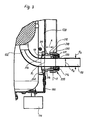
- Fig. 3 shows in particular the holder 200, which holds the liquid-carrying pipe 130.
- a flexible hose 132 is connected in the embodiment.
- the flexible hose can be passed through the holder 200 without the need for a transition between the flexible hose and the pipe 130 and / or that the pipe 130 can be dispensed with.
- the tube 130 is made of brass.
- the tube 130 is held by a seal, in particular a flexible seal 220.
- the seal 220 in turn is fixed in a tube piece 210, in the exemplary embodiment by radially around the seal 220 arranged rods 214.
- a nut 230 engages in an external thread 212 of the tube piece 210 and exerts a force on the seal 220 so that it against the Tube 130 is pressed.
- the seal can not slip out.
- In the axial direction is located as a stop for the seal an inwardly directed shoulder 216 in the tube piece 210. It is advantageous to transfer the force of the nut 230 on the rods 214, which transmit the force to the seal 220 and engage in this.
- the holder is guided through the opening 121 of the wall 120, and the wall 120 connects to a shoulder 215 of the pipe section 210. With a nut 240 that sits on an external thread 213, the holder 200 is attached to the wall 120.
- the inner diameter R I of the pipe section 210 is at least in the region of the distance A greater than the diameter R A of the tube 130.
- the distance A results from the wall 120 to the seal 220, in the embodiment, the distance A corresponds approximately to the pipe diameter R R.
- the holder 200 thus has a tube piece 210 with at least one external thread 212. Furthermore, a seal 220 is inserted into the tube piece 210 inside, which is held in particular by flexible rods 214 of the tube piece 210.
- the pipe section 210 at least partially has a larger inner diameter R I than an outer diameter R A of the pipe 130; in particular, the inner diameter R I is greater at least approximately by a wall thickness of the pipe 130 or a wall thickness of the pipe section 210.
- the pipe section 210 in the region of the distance A has a larger inner diameter R I than the outer diameter R A of the tube 130, in particular, the inner diameter R I by at least about 1 mm larger than the outer diameter of the tube 130th
- the pipe section 210 has a shoulder 215, which is pressed against the wall 120 with a nut 240, which is screwed onto an external thread 213 of the pipe section 210.
Landscapes
- Engineering & Computer Science (AREA)
- Chemical & Material Sciences (AREA)
- Combustion & Propulsion (AREA)
- Mechanical Engineering (AREA)
- General Engineering & Computer Science (AREA)
- Cooling Or The Like Of Electrical Apparatus (AREA)
- Structures Of Non-Positive Displacement Pumps (AREA)
Abstract
Description
- Die Erfindung betrifft ein Kühl- und/oder Heizgerät, insbesondere eine Wärmepumpe, mit einer Halterung für ein flüssigkeitsführendes Rohr, welches von erwärmter oder gekühlter Flüssigkeit durchströmt wird und durch eine Öffnung einer Wand des Kühl- und/oder Heizgerätes geführt ist.
- Im folgenden ist als Ausführungsbeispiel ein Teil einer Wärmepumpe gewählt, in dem sich Rohre befinden, die aus der Wärmepumpe herausgeführt sind.
- Kühl- und/oder Heizgeräte, insbesondere Wärmepumpen, weisen im Inneren einen Kältemittelkreislauf auf, mit dem Wärme und/oder Kälte erzeugt wird. Bei Wärmepumpen, mit denen eine Flüssigkeit erwärmt und/oder gekühlt wird, wird die Energie mittels eines Fluids über Rohrleitungen an ein Heizungs-, Kühl- oder Warmwassersystem abgegeben. Hierzu sind die Rohrleitungen durch eine Wand der Wärmepumpe geführt. Im einfachsten Fall befindet sich in der Wand eine großzügige Öffnung, die wesentlich größer ist als der Außendurchmesser der Rohrleitungen. Die Öffnungen können einen Versatz oder ein Spiel der Rohrleitungen ausgleichen. Die Rohrleitungen liegen dabei nicht an den Wänden an. Marktbekannt sind auch Rohrdurchführungen, bei denen die Rohdeitungen durch die Wand geführt sind und mit dieser über die Rohrdurchführung verbunden sind.
- Die Wärme- und/oder Kälteabgabe erfolgt vorzugsweise über Heiz- oder Kühlkörper, in die Rohrleitungen geführt sind, die das Fluid führen.
- Aufgabe der Erfindung ist es, ein flüssigkeitsführendes Rohr einer Wärmepumpe durch eine Wand, insbesondere Gehäusewand der Wärmepumpe, zu führen und gleichzeitig an der Wand zu befestigen, wobei die Wärmeleitung zwischen Rohr und Wand möglichst gering sein soll.
- Gelöst ist die Aufgabe durch die Merkmale des Anspruchs 1. Vorteilhafte Ausführungsformen der Erfindung sind in den Unteransprüchen gegeben. Demnach liegt ein flüssigkeitsführendes Rohr in einer Halterung und ist in einer Ebene gehalten, die zu einer Wand, insbesondere einer Gehäusewand eines Kühl- oder Heizgerätes, im Ausführungsbeispiel einer Wärmepumpe, in der sich eine Öffnung befindet, einen Abstand hat.
- Durch den Abstand, der vorzugsweise größer ist als die Wandstärke der Wand, insbesondere größer ist als eine Wandstärke von ca. 1 mm eines Bleches der Wand, ist eine Wärmeleitung vom Rohr auf die Wand und das Gehäuse vermieden. Hierdurch ist eine Wärmeentkopplung zwischen Rohr und Wand erreicht und das Rohr ist gleichzeitig mit der Wand verbunden. Dies ist insbesondere von Bedeutung, wenn mit Wärmepumpen z.B. im Umkehrbetrieb eines Kältemittelkreislaufs der Wärmepumpe Kälte erzeugt wird und somit durch die Rohrleitungen ein Wärmeträgermedium geführt wird, z.B. Kühlwasser für die Kühlung, welches eine niedrigere Temperatur als die Umgebungsluft aufweist, insbesondere eine Temperatur unter dem Taupunkt der Umgebungstemperatur. Durch die Wärmeentkopplung wird die Übertragung von Kälte oder Wärme auf eine Wand des Kühl- oder Heizgerätes, insbesondere einer Wärmepumpe, vermieden.
- Als vorteilhaft hat es sich dabei erwiesen, dass der Abstand größer ist als etwa die Hälfte eines Rohrdurchmessers, insbesondere größer als ca. 10 mm. Weiterhin vorteilhaft ist es, wenn die Halterung wenigstens teilweise aus einem Kunststoff besteht, insbesondere wenn die Halterung im Bereich des Abstandes aus Kunststoff besteht. In die Halterung ist eine Dichtung eingelegt. Gemäß einem weiteren Ausführungsbeispiel ist bei einer Halterung aus Kunststoff die Dichtung in einem Zweikomponenten-Spritzgießverfahren an die Halterung angespritzt.
- Weiterhin sind mit der vorgeschlagenen Halterung die Schallemissionen verringert.
- Körperschall, insbesondere Schwingungen, die vom Verdichter auf die Rohre übertragen werden, können sich nur stark gedämpft auf die Gehäuseteile erstrecken. Die Dämpfung wird auch durch die Dichtung erreicht, insbesondere, wenn diese gummielastisch ausgeführt ist.
- Je nach Aufstellungsort der Wärmepumpe wird diese den entsprechenden Umweltbelastungen ausgesetzt; bei einer Aufstellung im Freien z.B. durch Regen. Die Halterung kann die Schutzart IP68 erreichen, wodurch kein Staub oder auch unter Druck stehendes Wasser in die Wärmepumpe eindringen kann. Das Kühl- und/oder Heizgerät erreicht in einem Ausführungsbeispiel somit wenigstens die Schutzart IP44.
- Die Halterung ist ebenfalls in Heiz- und Kühlkörpern, die ein Heiz- und/oder Kühlgerät im Sinne der Erfindung darstellen, eingesetzt. Den Heiz- und Kühlkörpern wird durch Rohrleitungen ein gekühltes oder erwärmtes Fluid zugeführt und der Raum wird erwärmt oder gekühlt. Mit der Halterung sind diese Rohrleitungen vorzugsweise in einem Gehäuse oder Rahmen der Heiz- und Kühlkörper gehalten.
- Erfindungsgemäß wird mit der Halterung somit ein Rohr wärmegedämmt in eine Wand eines Heiz- und/oder Kühlgerätes geführt, wobei ein Fluid, welches gekühlt oder erwärmt ist, durch das Rohr fließt. Je nach Stellung des Umschaltventils wird das Fluid von einer Pumpe entweder durch den Heizungsvorlauf oder den Warmwasservorlauf gepumpt. Somit wird durch die Wärmedämmung der Halterung kaum Kälte oder Wärme des Fluids an die Wand übertragen.
- Bei einer Wärmepumpe, die Erdwärme aus einem Erdkollektor, einem Erdspieß oder einem Brunnen bezieht, wird eine Soleleitung in die Wärmepumpe und wieder heraus geführt. Diese Sole wird in einen Verdampfer der Wärmepumpe geleitet und gibt dort Energie ab. Je nach Umgebungstemperatur fließt Sole mit einer Temperatur über oder unter dieser Umgebungstemperatur durch die Soleleitung. Die aus der Wärmepumpe herausfließende Sole wurde im Verdampfer abgekühlt. Die Soleleitung wird vorteilhaft in einer Halterung in die Wärmepumpe hinein- und/oder wieder herausgeführt. Die Erfindung ist auch auf elektrische Heizgeräte, wie Durchlauferhitzer o.ä. anwendbar, in die eine Kalt- und eine Warrrwasserleitung oder eine Vor- und Rücklaufleitung geführt wird.
- Im Ausführungsbeispiel ist eine Wärmepumpe gezeigt, die ein Gehäuse aufweist, in dem sich wenigstens teilweise ein Kältemittelkreislauf befindet. Der nicht dargestellte Kältemittelkreislauf besteht aus einem Verflüssiger, der als Wärmetauscher ausgeführt ist, oder der in vorteilhafter Weise in einem Behälter, der als Pufferspeicher dient und mit einer Isolierung versehen ist, angeordnet ist, einem Verdichter und einem Flüssigkeitssammler. Bei der Wärmepumpe gemäß dem Ausführungsbeispiel handelt es sich um eine Luft-Wasserwärmepumpe, in der sich ein nicht dargestellter Verdampfer des Kältemittelkreislaufs oberhalb einer Kondensatwanne befindet und in vorteilhafter Weise an einem Abtaublech anliegt. Über das Abtaublech wird Kondensat in die Kondensatwanne geführt und von dort über einen Kondensatablauf aus der Wärmepumpe herausgeführt. Weiterhin ist nicht dargestellt ein Ausdehnungsgefäß, ein Lüfter für die Zufuhr von Außenluft zum Verdampfer, sowie Luftführungssysteme undein Regler. Rohre für einen Warmwasservor- und -rücklauf sowie für einen Heizungsvor- und -rücklauf sind mit dem Behälter oder Wärmetauscher verbunden.
-
- Figur 1
- Teil einer Wärmepumpe mit Rohrdurchführung,
- Figur 2
- Draufsicht auf den Teil der Wärmepumpe nach
Fig. 1 , - Figur 3
- Halterung für die Rohrdurchführung.
-
Fig. 1 zeigt einen Teil einer Wärmepumpe 100 von hinten, wo durch eine Wand 120 eines Gehäuses 150 mehrere flüssigkeitsführende Rohre geführt sind. Unten sind durch die Wand 120 ein Rohr 104 für den Heizungsvorlauf, ein Rohr 105 für den Heizungsrücklauf, ein Rohr 106 für den Warmwasserrücklauf und ein Rohr 130 für den Warmwasservorlauf geführt. Weiter oben befindet sich ein Rohr 170 für den Ablauf von Wasser aus einem Sicherheitsventil. Daneben befindet sich der beschriebene Kondensatablauf 161. Eine große Öffnung 123, die mit einer Klappe verschlossen wird, wird als Serviceöffnung verwendet, um von hinten insbesondere an die Bauteile des Kältemittelkreislaufs zu gelangen. Die Rohre 104, 105, 106, 130, 170 und/oder das Rohr 161 des Kondensatablaufs sind mit einer Halterung 200 an der Wand 120 befestigt. -
Fig. 2 zeigt den Teil der Wärmepumpe 100 von oben, wobei noch eine Heizungspumpe 109 gezeigt ist, die Heizungswasser durch das Rohr 104 oder Warmwasser durch das Rohr 130 pumpt. Oberhalb der Isolierung des Behälters befindet sich ein Umschaltventil 108, mit dem zwischen Warmwasser- und Heizungsbetrieb umgeschaltet wird. -
Fig. 3 zeigt insbesondere die Halterung 200, die das flüssigkeitsführende Rohr 130 hält. An das flüssigkeitsführende Rohr 130 ist im Ausführungsbeispiel ein flexibler Schlauch 132 angeschlossen. Gemäß einer anderen Ausführung kann der flexible Schlauch durch die Halterung 200 geführt werden, ohne dass ein Übergang zwischen dem flexiblen Schlauch und dem Rohr 130 erforderlich wäre bzw. dass das Rohr 130 entfallen kann. Im Ausführungsbeispiel besteht das Rohr 130 aus Messing. Das Rohr 130 ist von einer Dichtung, insbesondere einer flexiblen Dichtung 220 gehalten. Die Dichtung 220 wiederum ist in einem Rohrstück 210 fixiert, im Ausführungsbeispiel durch radial um die Dichtung 220 angeordnete Stäbe 214. Eine Mutter 230 greift in ein Außengewinde 212 des Rohrstücks 210 ein und übt eine Kraft auf die Dichtung 220 aus, so dass diese gegen das Rohr 130 gepresst wird. Durch einen Absatz 231 der Mutter 230 kann die Dichtung nicht herausrutschen. In axialer Richtung befindet sich als Anschlag für die Dichtung ein nach innen gerichteter Absatz 216 im Rohrstück 210. Vorteilhaft ist es, die Kraft von der Mutter 230 auf die Stäbe 214 zu übertragen, die die Kraft auf die Dichtung 220 übertragen und in diese eingreifen.
Die Halterung ist durch die Öffnung 121 der Wand 120 geführt, und die Wand 120 schließt an einen Absatz 215 des Rohrstücks 210 an. Mit einer Mutter 240, die auf einem Außengewinde 213 sitzt, wird die Halterung 200 mit der Wand 120 befestigt. - Der Innendurchmesser RI des Rohrstücks 210 ist wenigstens im Bereich des Abstands A größer als der Durchmesser RA des Rohres 130. Der Abstand A ergibt sich von der Wand 120 bis zur Dichtung 220, im Ausführungsbeispiel entspricht der Abstand A in etwa dem Rohrdurchmesser RR. Durch die Ausführung des Rohrstücks 210 aus Kunststoff und den Abstand A wird eine Wärmeübertragung vom im Rohr 130 strömenden Fluid, zB. Heizungswasser oder Brauchwasser, vermieden. Somit wird auch die Leistungszahl der Wärmepumpe 100 verbessert, da weniger Wärme an die Umgebung abgegeben wird.
- Die Halterung 200 weist somit ein Rohrstück 210 mit wenigstens einem Außengewinde 212 auf. Weiterhin ist in das Rohrstück 210 innen eine Dichtung 220 eingesetzt, die insbesondere von flexiblen Stäben 214 des Rohrstücks 210 gehalten ist.
- Weiterhin ist die Dichtung 220 von einer auf das Rohrstück 210 aufgeschobenen Mutter 230 zusammengedrückt, insbesondere wirkt von der Mutter 230 eine Kraft auf die Stäbe 214, die sich verformen und die Dichtung 220 gegen das Rohr 130 pressen.
- Das Rohrstück 210 weist demnach zumindest teilweise einen größeren Innendurchmesser RI als einen Außendurchmesser RA des Rohres 130 auf, insbesondere ist der Innendurchmesser RI wenigstens etwa um eine Wandstärke des Rohres 130 oder eine Wandstärke des Rohrstücks 210 größer.
- Gemäß Ausführungsbeispiel hat das Rohrstück 210 im Bereich des Abstands A einen größeren Innendurchmesser RI als der Außendurchmesser RA des Rohres 130 ist, insbesondere ist der Innendurchmesser RI um wenigstens ca. 1 mm größer als der Außendurchmesser des Rohres 130.
- Das Rohrstück 210 hat einen Absatz 215, der mit einer Mutter 240, die auf ein Außengewinde 213 des Rohrstücks 210 aufgeschraubt ist, gegen die Wand 120 gedrückt ist.
Claims (11)
- Kühl- und/oder Heizgerät, insbesondere eine Wärmepumpe (100), mit einer Halterung (200) für ein flüssigkeitsführendes Rohr (130), welches von erwärmter oder gekühlter Flüssigkeit durchströmt wird und durch eine Öffnung (122) einer Wand (120) des Kühl- und/oder Heizgerätes geführt ist,
dadurch gekennzeichnet,
dass das Rohr (130) in der Halterung (200) liegt und in einer Ebene (E) gehalten ist, die zu der Wand (120), in der sich die Öffnung (122) befindet, einen Abstand (A) hat, wobei eine Wärmeentkopplung zwischen Rohr (130) und Wand (120) erreicht ist. - Kühl- und/oder Heizgerät nach Anspruch 1,
dadurch gekennzeichnet,
dass der Abstand (A) größer ist als die Wandstärke der Wand (120), insbesondere größer ist als die Wandstärke von ca. 1 mm eines Bleches der Wand (120). - Kühl- und/oder Heizgerät nach Anspruch 2,
dadurch gekennzeichnet,
dass der Abstand (A) größer ist als etwa die Hälfte eines Rohrdurchmessers (RR), insbesondere größer als ca. 10 mm. - Kühl- und/oder Heizgerät nach einem oder mehreren der vorhergehenden Ansprüche,
dadurch gekennzeichnet,
dass die Halterung (200) wenigstens teilweise aus einem Kunststoff besteht. - Kühl- und/oder Heizgerät nach einem oder mehreren der vorhergehenden Ansprüche,
dadurch gekennzeichnet,
dass die Halterung (200) ein Rohrstück (210) mit wenigstens einem Außengewinde (212) aufweist. - Kühl- und/oder Heizgerät nach einem oder mehreren der vorhergehenden Ansprüche,
dadurch gekennzeichnet,
dass das Rohrstück (210) innen eine Dichtung (220) aufweist, die insbesondere von flexiblen Stäben (214) des Rohrstücks (210) gehalten ist. - Kühl- und/oder Heizgerät nach einem oder mehreren der vorhergehenden Ansprüche,
dadurch gekennzeichnet,
dass die Dichtung (220) von einer auf das Rohrstück (210) aufgeschobenen Mutter (230) zusammengedrückt ist, insbesondere von der Mutter (230) eine Kraft auf die Stäbe (214) wirkt, die sich verformen und die Dichtung (220) gegen das Rohr (130) pressen. - Kühl- und/oder Heizgerät nach einem oder mehreren der vorhergehenden Ansprüche,
dadurch gekennzeichnet,
dass das Rohrstück (210) zumindest teilweise einen größeren Innendurchmesser (RI) aufweist als der Außendurchmesser (RA) des Rohres (130) ist, insbesondere der Innendurchmesser (RI) wenigstens etwa um eine Wandstärke des Rohres (130) oder eine Wandstärke des Rohrstücks (210) größer ist. - Kühl- und/oder Heizgerät nach einem oder mehreren der vorhergehenden Ansprüche,
dadurch gekennzeichnet,
dass das Rohrstück (210) im Bereich des Abstands (A) einen größeren Innendurchmesser (RI) aufweist als der Außendurchmesser (RA) des Rohres (130) ist, insbesondere einen um wenigstens ca. 1 mm größeren Innendurchmesser (RI) aufweist. - Kühl- und/oder Heizgerät nach einem oder mehreren der vorhergehenden Ansprüche,
dadurch gekennzeichnet,
dass das Rohrstück (210) einen Absatz (215) aufweist, gegen den die Wand (120) anliegt, und dass eine Mutter (240) auf ein Außengewinde (213) des Rohrstücks (210) aufgeschraubt ist und gegen die Wand (120) drückt. - Kühl- und/oder Heizgerät nach einem oder mehreren der vorhergehenden Ansprüche,
dadurch gekennzeichnet,
dass das Kühl- und/oder Heizgerät eine Schutzart IP 44 aufweist.
Applications Claiming Priority (1)
| Application Number | Priority Date | Filing Date | Title |
|---|---|---|---|
| DE200810024028 DE102008024028A1 (de) | 2008-05-16 | 2008-05-16 | Kühl- und/oder Heizgerät, insbesondere Wärmepumpe, mit einer Halterung für ein flüssigkeitsführendes Rohr |
Publications (2)
| Publication Number | Publication Date |
|---|---|
| EP2119978A1 true EP2119978A1 (de) | 2009-11-18 |
| EP2119978B1 EP2119978B1 (de) | 2012-11-28 |
Family
ID=41027115
Family Applications (1)
| Application Number | Title | Priority Date | Filing Date |
|---|---|---|---|
| EP20090006220 Active EP2119978B1 (de) | 2008-05-16 | 2009-05-07 | Kühl- und/oder Heizgeräte, insbesondere Wärmepumpe, mit einer Halterung für ein flüssigkeitsführendes Rohr |
Country Status (2)
| Country | Link |
|---|---|
| EP (1) | EP2119978B1 (de) |
| DE (1) | DE102008024028A1 (de) |
Cited By (1)
| Publication number | Priority date | Publication date | Assignee | Title |
|---|---|---|---|---|
| DE102021133191A1 (de) | 2021-12-15 | 2023-06-15 | Viessmann Climate Solutions Se | Wärmepumpenvorrichtung |
Citations (6)
| Publication number | Priority date | Publication date | Assignee | Title |
|---|---|---|---|---|
| JPH06123446A (ja) * | 1992-10-12 | 1994-05-06 | Matsushita Electric Ind Co Ltd | 空気調和機の室外ユニット |
| JP2001004199A (ja) * | 1999-06-22 | 2001-01-12 | Mitsubishi Electric Corp | 天井カセット形エアコンの室内機 |
| JP2003074910A (ja) * | 2001-08-31 | 2003-03-12 | Chofu Seisakusho Co Ltd | 空気調和機の室外機 |
| EP1323989A1 (de) * | 2000-10-03 | 2003-07-02 | Daikin Industries, Limited | Ausseneinheit einer klimaanlage |
| EP1568954A2 (de) * | 2004-02-25 | 2005-08-31 | LG Electronics Inc. | Rohranordnung einer Ausseneinheit in einer Klimaanlage |
| EP1767872A1 (de) | 2005-09-26 | 2007-03-28 | Sanyo Electric Co., Ltd. | Klimaanlage |
Family Cites Families (1)
| Publication number | Priority date | Publication date | Assignee | Title |
|---|---|---|---|---|
| US4444022A (en) * | 1981-01-12 | 1984-04-24 | Aluminum Company Of America | Water heating system |
-
2008
- 2008-05-16 DE DE200810024028 patent/DE102008024028A1/de active Pending
-
2009
- 2009-05-07 EP EP20090006220 patent/EP2119978B1/de active Active
Patent Citations (6)
| Publication number | Priority date | Publication date | Assignee | Title |
|---|---|---|---|---|
| JPH06123446A (ja) * | 1992-10-12 | 1994-05-06 | Matsushita Electric Ind Co Ltd | 空気調和機の室外ユニット |
| JP2001004199A (ja) * | 1999-06-22 | 2001-01-12 | Mitsubishi Electric Corp | 天井カセット形エアコンの室内機 |
| EP1323989A1 (de) * | 2000-10-03 | 2003-07-02 | Daikin Industries, Limited | Ausseneinheit einer klimaanlage |
| JP2003074910A (ja) * | 2001-08-31 | 2003-03-12 | Chofu Seisakusho Co Ltd | 空気調和機の室外機 |
| EP1568954A2 (de) * | 2004-02-25 | 2005-08-31 | LG Electronics Inc. | Rohranordnung einer Ausseneinheit in einer Klimaanlage |
| EP1767872A1 (de) | 2005-09-26 | 2007-03-28 | Sanyo Electric Co., Ltd. | Klimaanlage |
Cited By (2)
| Publication number | Priority date | Publication date | Assignee | Title |
|---|---|---|---|---|
| DE102021133191A1 (de) | 2021-12-15 | 2023-06-15 | Viessmann Climate Solutions Se | Wärmepumpenvorrichtung |
| EP4198417A1 (de) | 2021-12-15 | 2023-06-21 | Viessmann Climate Solutions SE | Wärmepumpenvorrichtung |
Also Published As
| Publication number | Publication date |
|---|---|
| EP2119978B1 (de) | 2012-11-28 |
| DE102008024028A1 (de) | 2009-11-19 |
Similar Documents
| Publication | Publication Date | Title |
|---|---|---|
| DE10008383A1 (de) | Schaltschrank oder Gehäuse mit einer Klimatisierungseinrichtung | |
| DE102007062002A1 (de) | Verflüssiger für ein Kältegerät | |
| DE202008002015U1 (de) | Modulare klimatechnische Anlage | |
| DE1102187B (de) | Waermepumpenanlage | |
| AT508737A2 (de) | Vorrichtung zur wärmeregelung | |
| EP2119978B1 (de) | Kühl- und/oder Heizgeräte, insbesondere Wärmepumpe, mit einer Halterung für ein flüssigkeitsführendes Rohr | |
| DE102010038368A1 (de) | Kältegerät, insbesondere Haushaltskältegerät | |
| EP2445769A1 (de) | Energieoptimiertes klimasystem für lokomotiven mit zwei führerstände | |
| DE202013101884U1 (de) | Vorrichtung zum Aufnehmen und Verdampfen von kondensierten Flüssigkeiten an einer Kälteanlage und Kälteanlage mit dieser Vorrichtung | |
| DE102007015859B4 (de) | Wärmetauscher, einer Kühlanordnung mit dem Wärmetauscher, sowie dessen Verwendung und Kühlverfahren | |
| WO2004104501A1 (de) | Kältegerät mit tauwasserverdampfer | |
| DE212022000172U1 (de) | Wärmepumpeneinheiten mit Wasseraustauscher | |
| DE102013207948A1 (de) | Kältegerät mit einer Zulaufleitung für Wasser | |
| DE102008004348A1 (de) | Redundantes Klimasystem für Lokomotiven | |
| DE60102726T2 (de) | Heizungs- und Klimaanlage | |
| DE102013207953A1 (de) | Kältegerät mit einem Wasserkreislauf | |
| DE102013207956A1 (de) | Kältegerät mit einem Wasseranschluss | |
| DE102012018021A1 (de) | Kühl- und/oder Gefriergerät | |
| DE69912014T2 (de) | Zentralheizung benutzende Heiz- und Klimaanlage | |
| DE202017004977U1 (de) | Aggregat zur Erzeugung von Wärme oder Kälte aus Umgebungsluft und Verwendungen dieses Aggregates | |
| EP2932168A1 (de) | Wärmepumpenanordnung und verfahren zum betrieb einer wärmepumpenanordnung | |
| DE3534304A1 (de) | Gas-fluessig-waermeuebertrager, insbesondere kuehlschrankverfluessiger | |
| DE102024119018A1 (de) | Temperierungssystem zur Temperierung mindestens eines Raums eines Gebäudes sowie Verfahren zur Temperierung mindestens eines Raums eines Gebäudes sowie Gebäude sowie Klimagerät | |
| DE102023118543A1 (de) | Verfahren und Vorrichtung zum Betrieb einer Kälteanlage mit Abwärmenutzung | |
| WO2025103972A1 (de) | Temperierungssystem zur temperierung mindestens eines raums eines gebäudes sowie verfahren zur temperierung mindestens eines raums eines gebäudes sowie gebäude sowie klimagerät |
Legal Events
| Date | Code | Title | Description |
|---|---|---|---|
| PUAI | Public reference made under article 153(3) epc to a published international application that has entered the european phase |
Free format text: ORIGINAL CODE: 0009012 |
|
| AK | Designated contracting states |
Kind code of ref document: A1 Designated state(s): AT BE BG CH CY CZ DE DK EE ES FI FR GB GR HR HU IE IS IT LI LT LU LV MC MK MT NL NO PL PT RO SE SI SK TR |
|
| 17P | Request for examination filed |
Effective date: 20100518 |
|
| 17Q | First examination report despatched |
Effective date: 20100617 |
|
| RAP1 | Party data changed (applicant data changed or rights of an application transferred) |
Owner name: STIEBEL ELTRON GMBH & CO. KG |
|
| 17Q | First examination report despatched |
Effective date: 20100908 |
|
| GRAP | Despatch of communication of intention to grant a patent |
Free format text: ORIGINAL CODE: EPIDOSNIGR1 |
|
| GRAS | Grant fee paid |
Free format text: ORIGINAL CODE: EPIDOSNIGR3 |
|
| GRAA | (expected) grant |
Free format text: ORIGINAL CODE: 0009210 |
|
| AK | Designated contracting states |
Kind code of ref document: B1 Designated state(s): AT BE BG CH CY CZ DE DK EE ES FI FR GB GR HR HU IE IS IT LI LT LU LV MC MK MT NL NO PL PT RO SE SI SK TR |
|
| REG | Reference to a national code |
Ref country code: GB Ref legal event code: FG4D Free format text: NOT ENGLISH |
|
| RIN1 | Information on inventor provided before grant (corrected) |
Inventor name: HOERSTING, ALEXANDER Inventor name: HOLLE, BJOERN Inventor name: KIRCHHOFF, HARTMUT |
|
| REG | Reference to a national code |
Ref country code: CH Ref legal event code: EP |
|
| REG | Reference to a national code |
Ref country code: AT Ref legal event code: REF Ref document number: 586399 Country of ref document: AT Kind code of ref document: T Effective date: 20121215 |
|
| REG | Reference to a national code |
Ref country code: IE Ref legal event code: FG4D Free format text: LANGUAGE OF EP DOCUMENT: GERMAN |
|
| REG | Reference to a national code |
Ref country code: DE Ref legal event code: R096 Ref document number: 502009005471 Country of ref document: DE Effective date: 20130124 |
|
| REG | Reference to a national code |
Ref country code: NL Ref legal event code: VDEP Effective date: 20121128 |
|
| REG | Reference to a national code |
Ref country code: LT Ref legal event code: MG4D |
|
| PG25 | Lapsed in a contracting state [announced via postgrant information from national office to epo] |
Ref country code: LT Free format text: LAPSE BECAUSE OF FAILURE TO SUBMIT A TRANSLATION OF THE DESCRIPTION OR TO PAY THE FEE WITHIN THE PRESCRIBED TIME-LIMIT Effective date: 20121128 Ref country code: FI Free format text: LAPSE BECAUSE OF FAILURE TO SUBMIT A TRANSLATION OF THE DESCRIPTION OR TO PAY THE FEE WITHIN THE PRESCRIBED TIME-LIMIT Effective date: 20121128 Ref country code: SE Free format text: LAPSE BECAUSE OF FAILURE TO SUBMIT A TRANSLATION OF THE DESCRIPTION OR TO PAY THE FEE WITHIN THE PRESCRIBED TIME-LIMIT Effective date: 20121128 Ref country code: ES Free format text: LAPSE BECAUSE OF FAILURE TO SUBMIT A TRANSLATION OF THE DESCRIPTION OR TO PAY THE FEE WITHIN THE PRESCRIBED TIME-LIMIT Effective date: 20130311 Ref country code: NO Free format text: LAPSE BECAUSE OF FAILURE TO SUBMIT A TRANSLATION OF THE DESCRIPTION OR TO PAY THE FEE WITHIN THE PRESCRIBED TIME-LIMIT Effective date: 20130228 |
|
| PG25 | Lapsed in a contracting state [announced via postgrant information from national office to epo] |
Ref country code: PT Free format text: LAPSE BECAUSE OF FAILURE TO SUBMIT A TRANSLATION OF THE DESCRIPTION OR TO PAY THE FEE WITHIN THE PRESCRIBED TIME-LIMIT Effective date: 20130328 Ref country code: CY Free format text: LAPSE BECAUSE OF FAILURE TO SUBMIT A TRANSLATION OF THE DESCRIPTION OR TO PAY THE FEE WITHIN THE PRESCRIBED TIME-LIMIT Effective date: 20121128 Ref country code: SI Free format text: LAPSE BECAUSE OF FAILURE TO SUBMIT A TRANSLATION OF THE DESCRIPTION OR TO PAY THE FEE WITHIN THE PRESCRIBED TIME-LIMIT Effective date: 20121128 Ref country code: LV Free format text: LAPSE BECAUSE OF FAILURE TO SUBMIT A TRANSLATION OF THE DESCRIPTION OR TO PAY THE FEE WITHIN THE PRESCRIBED TIME-LIMIT Effective date: 20121128 Ref country code: PL Free format text: LAPSE BECAUSE OF FAILURE TO SUBMIT A TRANSLATION OF THE DESCRIPTION OR TO PAY THE FEE WITHIN THE PRESCRIBED TIME-LIMIT Effective date: 20121128 Ref country code: GR Free format text: LAPSE BECAUSE OF FAILURE TO SUBMIT A TRANSLATION OF THE DESCRIPTION OR TO PAY THE FEE WITHIN THE PRESCRIBED TIME-LIMIT Effective date: 20130301 |
|
| PG25 | Lapsed in a contracting state [announced via postgrant information from national office to epo] |
Ref country code: EE Free format text: LAPSE BECAUSE OF FAILURE TO SUBMIT A TRANSLATION OF THE DESCRIPTION OR TO PAY THE FEE WITHIN THE PRESCRIBED TIME-LIMIT Effective date: 20121128 Ref country code: CZ Free format text: LAPSE BECAUSE OF FAILURE TO SUBMIT A TRANSLATION OF THE DESCRIPTION OR TO PAY THE FEE WITHIN THE PRESCRIBED TIME-LIMIT Effective date: 20121128 Ref country code: SK Free format text: LAPSE BECAUSE OF FAILURE TO SUBMIT A TRANSLATION OF THE DESCRIPTION OR TO PAY THE FEE WITHIN THE PRESCRIBED TIME-LIMIT Effective date: 20121128 Ref country code: DK Free format text: LAPSE BECAUSE OF FAILURE TO SUBMIT A TRANSLATION OF THE DESCRIPTION OR TO PAY THE FEE WITHIN THE PRESCRIBED TIME-LIMIT Effective date: 20121128 Ref country code: BG Free format text: LAPSE BECAUSE OF FAILURE TO SUBMIT A TRANSLATION OF THE DESCRIPTION OR TO PAY THE FEE WITHIN THE PRESCRIBED TIME-LIMIT Effective date: 20130228 |
|
| PG25 | Lapsed in a contracting state [announced via postgrant information from national office to epo] |
Ref country code: IT Free format text: LAPSE BECAUSE OF FAILURE TO SUBMIT A TRANSLATION OF THE DESCRIPTION OR TO PAY THE FEE WITHIN THE PRESCRIBED TIME-LIMIT Effective date: 20121128 Ref country code: RO Free format text: LAPSE BECAUSE OF FAILURE TO SUBMIT A TRANSLATION OF THE DESCRIPTION OR TO PAY THE FEE WITHIN THE PRESCRIBED TIME-LIMIT Effective date: 20121128 Ref country code: NL Free format text: LAPSE BECAUSE OF FAILURE TO SUBMIT A TRANSLATION OF THE DESCRIPTION OR TO PAY THE FEE WITHIN THE PRESCRIBED TIME-LIMIT Effective date: 20121128 |
|
| PLBE | No opposition filed within time limit |
Free format text: ORIGINAL CODE: 0009261 |
|
| STAA | Information on the status of an ep patent application or granted ep patent |
Free format text: STATUS: NO OPPOSITION FILED WITHIN TIME LIMIT |
|
| 26N | No opposition filed |
Effective date: 20130829 |
|
| PG25 | Lapsed in a contracting state [announced via postgrant information from national office to epo] |
Ref country code: HR Free format text: LAPSE BECAUSE OF FAILURE TO SUBMIT A TRANSLATION OF THE DESCRIPTION OR TO PAY THE FEE WITHIN THE PRESCRIBED TIME-LIMIT Effective date: 20121128 |
|
| BERE | Be: lapsed |
Owner name: STIEBEL ELTRON G.M.B.H. & CO. KG Effective date: 20130531 |
|
| REG | Reference to a national code |
Ref country code: DE Ref legal event code: R097 Ref document number: 502009005471 Country of ref document: DE Effective date: 20130829 |
|
| PG25 | Lapsed in a contracting state [announced via postgrant information from national office to epo] |
Ref country code: MC Free format text: LAPSE BECAUSE OF FAILURE TO SUBMIT A TRANSLATION OF THE DESCRIPTION OR TO PAY THE FEE WITHIN THE PRESCRIBED TIME-LIMIT Effective date: 20121128 |
|
| REG | Reference to a national code |
Ref country code: CH Ref legal event code: PL |
|
| GBPC | Gb: european patent ceased through non-payment of renewal fee |
Effective date: 20130507 |
|
| PG25 | Lapsed in a contracting state [announced via postgrant information from national office to epo] |
Ref country code: CH Free format text: LAPSE BECAUSE OF NON-PAYMENT OF DUE FEES Effective date: 20130531 Ref country code: LI Free format text: LAPSE BECAUSE OF NON-PAYMENT OF DUE FEES Effective date: 20130531 |
|
| REG | Reference to a national code |
Ref country code: IE Ref legal event code: MM4A |
|
| PG25 | Lapsed in a contracting state [announced via postgrant information from national office to epo] |
Ref country code: BE Free format text: LAPSE BECAUSE OF NON-PAYMENT OF DUE FEES Effective date: 20130531 |
|
| REG | Reference to a national code |
Ref country code: FR Ref legal event code: ST Effective date: 20140131 |
|
| PG25 | Lapsed in a contracting state [announced via postgrant information from national office to epo] |
Ref country code: GB Free format text: LAPSE BECAUSE OF NON-PAYMENT OF DUE FEES Effective date: 20130507 Ref country code: IE Free format text: LAPSE BECAUSE OF NON-PAYMENT OF DUE FEES Effective date: 20130507 |
|
| PG25 | Lapsed in a contracting state [announced via postgrant information from national office to epo] |
Ref country code: FR Free format text: LAPSE BECAUSE OF NON-PAYMENT OF DUE FEES Effective date: 20130531 |
|
| PG25 | Lapsed in a contracting state [announced via postgrant information from national office to epo] |
Ref country code: MT Free format text: LAPSE BECAUSE OF FAILURE TO SUBMIT A TRANSLATION OF THE DESCRIPTION OR TO PAY THE FEE WITHIN THE PRESCRIBED TIME-LIMIT Effective date: 20121128 |
|
| PG25 | Lapsed in a contracting state [announced via postgrant information from national office to epo] |
Ref country code: TR Free format text: LAPSE BECAUSE OF FAILURE TO SUBMIT A TRANSLATION OF THE DESCRIPTION OR TO PAY THE FEE WITHIN THE PRESCRIBED TIME-LIMIT Effective date: 20121128 |
|
| PG25 | Lapsed in a contracting state [announced via postgrant information from national office to epo] |
Ref country code: MK Free format text: LAPSE BECAUSE OF FAILURE TO SUBMIT A TRANSLATION OF THE DESCRIPTION OR TO PAY THE FEE WITHIN THE PRESCRIBED TIME-LIMIT Effective date: 20121128 Ref country code: HU Free format text: LAPSE BECAUSE OF FAILURE TO SUBMIT A TRANSLATION OF THE DESCRIPTION OR TO PAY THE FEE WITHIN THE PRESCRIBED TIME-LIMIT; INVALID AB INITIO Effective date: 20090507 Ref country code: LU Free format text: LAPSE BECAUSE OF NON-PAYMENT OF DUE FEES Effective date: 20130507 |
|
| PG25 | Lapsed in a contracting state [announced via postgrant information from national office to epo] |
Ref country code: IS Free format text: LAPSE BECAUSE OF FAILURE TO SUBMIT A TRANSLATION OF THE DESCRIPTION OR TO PAY THE FEE WITHIN THE PRESCRIBED TIME-LIMIT Effective date: 20121128 |
|
| P01 | Opt-out of the competence of the unified patent court (upc) registered |
Effective date: 20230524 |
|
| PGFP | Annual fee paid to national office [announced via postgrant information from national office to epo] |
Ref country code: DE Payment date: 20250521 Year of fee payment: 17 |
|
| PGFP | Annual fee paid to national office [announced via postgrant information from national office to epo] |
Ref country code: AT Payment date: 20250522 Year of fee payment: 17 |