EP2122084B1 - Lot de pièces comprenant un dispositif de fixation et un moyen d'ancrage - Google Patents
Lot de pièces comprenant un dispositif de fixation et un moyen d'ancrage Download PDFInfo
- Publication number
- EP2122084B1 EP2122084B1 EP08707707A EP08707707A EP2122084B1 EP 2122084 B1 EP2122084 B1 EP 2122084B1 EP 08707707 A EP08707707 A EP 08707707A EP 08707707 A EP08707707 A EP 08707707A EP 2122084 B1 EP2122084 B1 EP 2122084B1
- Authority
- EP
- European Patent Office
- Prior art keywords
- transmission element
- power transmission
- force
- anchor
- fastening device
- Prior art date
- Legal status (The legal status is an assumption and is not a legal conclusion. Google has not performed a legal analysis and makes no representation as to the accuracy of the status listed.)
- Not-in-force
Links
- 210000000078 claw Anatomy 0.000 claims description 14
- 238000010008 shearing Methods 0.000 claims description 8
- 239000000853 adhesive Substances 0.000 claims 1
- 230000001070 adhesive effect Effects 0.000 claims 1
- 238000007688 edging Methods 0.000 claims 1
- 230000005540 biological transmission Effects 0.000 abstract description 114
- 238000009413 insulation Methods 0.000 description 15
- 238000005452 bending Methods 0.000 description 6
- 239000011490 mineral wool Substances 0.000 description 3
- 239000011494 foam glass Substances 0.000 description 2
- 239000002184 metal Substances 0.000 description 2
- 239000000463 material Substances 0.000 description 1
- 229920001296 polysiloxane Polymers 0.000 description 1
- 238000004080 punching Methods 0.000 description 1
Images

Classifications
-
- E—FIXED CONSTRUCTIONS
- E04—BUILDING
- E04B—GENERAL BUILDING CONSTRUCTIONS; WALLS, e.g. PARTITIONS; ROOFS; FLOORS; CEILINGS; INSULATION OR OTHER PROTECTION OF BUILDINGS
- E04B1/00—Constructions in general; Structures which are not restricted either to walls, e.g. partitions, or floors or ceilings or roofs
- E04B1/62—Insulation or other protection; Elements or use of specified material therefor
- E04B1/74—Heat, sound or noise insulation, absorption, or reflection; Other building methods affording favourable thermal or acoustical conditions, e.g. accumulating of heat within walls
- E04B1/76—Heat, sound or noise insulation, absorption, or reflection; Other building methods affording favourable thermal or acoustical conditions, e.g. accumulating of heat within walls specifically with respect to heat only
- E04B1/762—Exterior insulation of exterior walls
- E04B1/7637—Anchoring of separate elements through the lining to the wall
-
- E—FIXED CONSTRUCTIONS
- E04—BUILDING
- E04B—GENERAL BUILDING CONSTRUCTIONS; WALLS, e.g. PARTITIONS; ROOFS; FLOORS; CEILINGS; INSULATION OR OTHER PROTECTION OF BUILDINGS
- E04B1/00—Constructions in general; Structures which are not restricted either to walls, e.g. partitions, or floors or ceilings or roofs
- E04B1/62—Insulation or other protection; Elements or use of specified material therefor
- E04B1/74—Heat, sound or noise insulation, absorption, or reflection; Other building methods affording favourable thermal or acoustical conditions, e.g. accumulating of heat within walls
- E04B1/76—Heat, sound or noise insulation, absorption, or reflection; Other building methods affording favourable thermal or acoustical conditions, e.g. accumulating of heat within walls specifically with respect to heat only
- E04B1/762—Exterior insulation of exterior walls
-
- E—FIXED CONSTRUCTIONS
- E04—BUILDING
- E04F—FINISHING WORK ON BUILDINGS, e.g. STAIRS, FLOORS
- E04F13/00—Coverings or linings, e.g. for walls or ceilings
- E04F13/07—Coverings or linings, e.g. for walls or ceilings composed of covering or lining elements; Sub-structures therefor; Fastening means therefor
- E04F13/08—Coverings or linings, e.g. for walls or ceilings composed of covering or lining elements; Sub-structures therefor; Fastening means therefor composed of a plurality of similar covering or lining elements
- E04F13/0801—Separate fastening elements
- E04F13/0803—Separate fastening elements with load-supporting elongated furring elements between wall and covering elements
- E04F13/0805—Separate fastening elements with load-supporting elongated furring elements between wall and covering elements with additional fastening elements between furring elements and the wall
-
- E—FIXED CONSTRUCTIONS
- E04—BUILDING
- E04F—FINISHING WORK ON BUILDINGS, e.g. STAIRS, FLOORS
- E04F13/00—Coverings or linings, e.g. for walls or ceilings
- E04F13/07—Coverings or linings, e.g. for walls or ceilings composed of covering or lining elements; Sub-structures therefor; Fastening means therefor
- E04F13/08—Coverings or linings, e.g. for walls or ceilings composed of covering or lining elements; Sub-structures therefor; Fastening means therefor composed of a plurality of similar covering or lining elements
- E04F13/0801—Separate fastening elements
- E04F13/0832—Separate fastening elements without load-supporting elongated furring elements between wall and covering elements
- E04F13/0857—Supporting consoles, e.g. adjustable only in a direction parallel to the wall
Definitions
- the invention relates to a kit of parts comprising a fastening device and an armature according to the preamble of patent claim 1.
- Such a fastening device with a front power transmission element and a rear power transmission element, wherein an armature can be passed through the front power transmission element and the rear power transmission element is made of DE 295 09 418 known.
- the fastening device is used to attach an object to a vertical outer wall of a building at a distance that is predetermined, for example, by the thickness of a heat-insulating insulation, thereby reducing the bending moment acting on the anchor.
- the rear power transmission element in this context is a power transmission element, which faces the outer wall
- the front power transmission element in this context is a force transmission element, which faces away from the outer wall.
- the front power transmission member is formed as an outer sleeve member and the rear power transmission member is formed as an inner sleeve member, the outer sleeve member having an internal thread and the inner sleeve member having an external thread, so that the outer sleeve member and the inner sleeve member are screwed together and the fastening device is adjustable ,
- a bore is formed in the middle of the outer sleeve part and in the middle of the inner sleeve part in each case a bore is formed.
- the anchor is passed through the bore in the outer sleeve part and the bore in the inner sleeve part to form an annular gap and anchored in a vertical outer wall of a building, which has a heat-insulating insulation.
- the bore in the front power transmission element and the bore in the rear power transmission element to a similar excess over the armature.
- a fastening device with a front power transmission element and a rear power transmission element is known.
- an armature is passed through a hole in the front power transmission element and a hole in the rear power transmission element and anchored in an outer wall, on which an insulation is arranged.
- the hole in the front power transmission element is formed further than the hole in the rear power transmission element. If the fastening device is rotated relative to the armature, the rotation of the fastening device is limited by the fact that the armature abuts against two opposite edges of the hole in the rear power transmission element, through which the armature is passed.
- the armature does not abut the hole in the front power transmission member whereby, in the assembled condition, a shearing force caused by a load is transmitted from the front power transmission member to the rear power transmission member and only from the latter directly to the outer wall on the armature.
- the anchor can be relatively small dimensions, since virtually no bending moment acts on the anchor.
- the present invention has for its object to provide such a fastening device, which is easy to assemble.
- the kit of parts according to the invention comprises a fastening device with a front power transmission element and a rear power transmission element, and an armature, wherein the armature through a hole in the front power transmission element and a hole in the rear power transmission element can be passed.
- the anchor is anchored in an outer wall.
- the hole in the front power transmission member is formed wider than the hole in the rear power transmission member such that when the fastening device is rotated relative to the armature, the rotation of the fastening device is limited by the armature abutting two opposite edges of the hole in the rear power transmission member. through which the anchor is passed.
- the armature does not abut the hole in the front power transmission member, whereby a shearing force caused by a load in the mounted state is transferable from the front power transmission member to the rear power transmission member and exclusively from the latter directly to the outer wall on the armature.
- Characteristic of the kit of parts according to the invention is that the anchor fixes the fastening device such that a tensile force caused by a load from the front power transmission element is directly transferable to the anchor.
- the front power transmission element and the rear power transmission element are designed such that a shearing force can be transmitted exclusively from the rear power transmission element to the armature.
- the term "exclusively” means that at least the vast majority of the shear force from the rear power transmission element is transferable to the anchor, because even if a small proportion of the shear force, for example via a silicone seal between the armature and front power transmission element is transmitted, the advantage remains obtained that compared to the known fastening devices, a comparatively smaller anchor can be used.
- a shearing force in the immediate vicinity of the outer wall can be transferred to the armature so that no large bending moment acts on the armature. Therefore, a relatively thin anchor is sufficient and no large-scale thermal bridge is formed.
- anchor is to be understood in this context as very comprehensive and is intended to denote any element that can be anchored in the outer wall.
- the front power transmission element and the rear power transmission element are designed such that a Shearing force of the front power transmission element via an insulating element to the rear power transmission element is transferable.
- claws are formed on the front power transmission element, which engage in the insulating element.
- "claws” are generally and widely to be understood as a positive connection.
- a material connection in particular based on a bond is possible. This allows particularly simple component geometries.
- claws are particularly suitable for transmitting a force which is directed perpendicular to the longitudinal axis of the armature.
- claws are formed on the rear power transmission element, which engage in the insulating element.
- the front power transmission element and the rear power transmission element are interconnected via a diagonal strut.
- the attachment device comprises a console body to which the rear power transmission element and the front power transmission element are connected.
- such a console body with low thermal conductivity can be produced.
- the console body is round. He can thus easily in an existing thermal insulation, such as a Layer of mineral wool, fit by using a hole saw a matching recess in the thermal insulation is created.
- the console body has a border.
- a gap between the console body and the insulation can be avoided.
- the fastening device has an anti-rotation device which prevents twisting, in particular of the rear power transmission element relative to the wall.
- a possible rotation about an axis substantially parallel to the armature is meant.
- another anchor through the front power transmission element and the rear power transmission element can be passed.
- rotation of the power transmission device can be prevented.
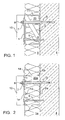
- Fig. 1 shows a cross-sectional view of a fastening device with a diagonal strut 6.
- the fastening device comprises a front power transmission element 1 and a rear power transmission element 2, both of which are plate-shaped and arranged parallel to each other.
- an insulating element 20 Between the front power transmission element 1 and the rear power transmission element 2 is an insulating element 20, which consists for example of easily deformable mineral wool.
- the front power transmission element 1 and the rear power transmission element 2 are connected to each other via the diagonal strut 6 and cross braces 11, formed integrally with these and made of plastic. Instead of plastic, metal can also be used if a higher load is required.
- the insulating element 20 is separated from an insulation 5 of the outer wall 4 by the console housing.
- An armature 3 is passed through a hole in the front power transmission member 1, a hole in the insulating member 5 and a hole in the rear power transmission member 2, and is anchored in the outer wall 4.
- the console housing may alternatively contain only air.
- the force caused by the load has a parallel force component directed parallel to the longitudinal axis of the armature 3 and a vertical force component (shear force) directed perpendicular to the longitudinal axis of the armature 3.
- the parallel force component as far as it is remote from the outer wall 4 (tensile force), from the front power transmission element 1 directly to the armature 3, and as far as the Outside wall 4 is facing (pressure force) from the front power transmission element 1, the cross braces 11 and the diagonal struts 6 transmitted to the outer wall 4.
- the vertical force component is transmitted from the front power transmission element 1 to the cross braces 11 and the diagonal brace 6, so that the armature does not act as a long lever.
- the vertical force component is then transmitted from the transverse struts 11 and the diagonal strut 6 on the rear power transmission element 2 and transmitted from this close to the outer wall 4 on the armature 3, so that only a small bending moment acts on the armature 3.
- the front power transmission element 1 and the rear power transmission element 2 is designed such that a shearing force can only be transmitted from the rear power transmission element 2 to the armature 3.
- the hole in the front power transmission element 1 is formed further than the hole in the rear power transmission element 2.
- the width of the hole in the insulating element 20 is not critical, as long as the insulating element 20 is easily deformable .
- Such a size ratio of the holes in the front power transmission member 1, the insulating member 20 and the rear power transmission member 2 can be achieved, for example, by a conical bore. This type of power transmission essentially also applies to the other embodiments. Deviations are noted.
- a washer 9 is provided as an anti-rotation device through another hole in the front power transmission element 1, another hole in the insulation element 20, and another hole in the rear power transmission element between the nut 8 and the front power transmission element 1 2 and anchored in the wall 4 to prevent rotation of the fastening device.
- Fig. 2 shows a cross-sectional view of a fastening device with border 14.
- the vertical force component is transmitted substantially via the insulating member 20a from a front power transmission member 1a to a rear power transmission member 2a and transmitted therefrom to the armature 3.
- the insulating element 20a slightly deforms under the vertical force component (shear force), which is why the insulating element 20a is formed for example of foam glass.
- metal claws 12 are formed, which engage in the insulating element 20 a.
- the rear power transmission element 2a made of plastic has a frame 13 for positive connection with the insulating element 20a.
- a border 14 made of plastic with a bevelled rear side which is also filled with the insulating element 20a and serves to compress a surrounding insulation 5 made of mineral wool, so that there is no gap between the insulation 5 and the fastening device ,
- the frame 14 and the frame 13 together with the power transmission elements 1a and 2a, a console housing.
- claws could be formed on both of the power transmission members 1a and 2a, or claws could be formed on the lower power transmission member 2a and a frame on the upper power transmission member 1a, or could be attached to the upper power transmission member 1a and the lower power transmission element 2a frame may be formed.
- the power transmission elements 1a, 2a may also be additionally or alternatively adhered to the insulating element 20a for this embodiment and the other embodiments.
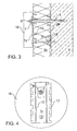
- Fig. 3 shows a cross-sectional view of a fastening device with a front power transmission element 1 b and a rear power transmission element 2 b, which are connected to each other via an insulating element 5 b.
- the front power transmission element 1 b with claws 12 and the rear power transmission element 2 b with claws 15 are interconnected exclusively via the insulating element 5 b, which with the insulation 5b of the outer wall 4 is identical.
- a console body is not present in this embodiment.
- Fig. 4 shows a view of a fastening device with a circular circumference.
- the front power transmission member 1 c and the rear power transmission member (hidden) are connected to the front and the back of a console body 16 having a circular cross section.
- the claws (hidden) are formed by punching out of the front fastener 1 c and bending for this and the other embodiments, so that recesses 17 arise.
- the console body consists either of an insulating element or comprises a housing in which an insulating element is included.
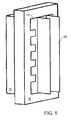
- Fig. 5 shows a perspective view of a fastener, which is designed as a console.
- the console comprises a console body with a front cuboid portion 18 and a rear cuboid portion 19, which form the housing of the console.
- the rear portion 19 has a smaller cross-sectional area than the front portion 18, so that between the front portion 18 and the rear portion 19, a step is formed and the front portion 19 forms a border.
- the border shall cover an insulation surrounding the console, so that no gap is formed between the console and the insulation.
- Fig. 6 shows a cross-sectional view of the fastening device Fig. 5 along its longitudinal direction.
- the fastening device Fig. 5 differs from the fastening device Fig. 2 only in that the border has no bevelled rear side.
- the console is therefore suitable for insulation that hardly yields, such as foam glass.
- Fig. 7 shows a cross-sectional view of the fastening device Fig. 5 along its transverse direction.
- the console body can also be designed as a one-piece insulating element without housing.
Landscapes
- Engineering & Computer Science (AREA)
- Architecture (AREA)
- Physics & Mathematics (AREA)
- Civil Engineering (AREA)
- Structural Engineering (AREA)
- Acoustics & Sound (AREA)
- Electromagnetism (AREA)
- Connection Of Plates (AREA)
Abstract
Claims (11)
- Ensemble de pièces incluant un dispositif de fixation comprenant un élément antérieur (1, 1a, 1b, 1c, 1d) de transmission de forces et un élément postérieur (2, 2a, 2b, 2d) de transmission de forces, ainsi qu'un tirant d'ancrage (3),- le tirant d'ancrage (3) pouvant être inséré à travers un trou pratiqué dans l'élément antérieur (1, 1a, 1b, 1c, 1d) de transmission de forces, et à travers un trou pratiqué dans l'élément postérieur (2, 2a, 2b, 2d) de transmission de forces,- ledit tirant d'ancrage (3) pouvant être assujetti dans une paroi extérieure (4),- le trou, pratiqué dans ledit élément antérieur (1, 1a, 1b, 1c, 1d) de transmission de forces, étant réalisé plus large que le trou pratiqué dans ledit élément postérieur (2, 2a, 2b, 2d) de transmission de forces, de telle sorte que, lorsque le dispositif de fixation est animé d'une rotation vis-à-vis du tirant d'ancrage (3), la rotation dudit dispositif de fixation soit limitée par venue en butée dudit tirant d'ancrage (3) contre deux bords opposés dudit trou pratiqué dans ledit élément postérieur (2, 2a, 2b, 2d) de transmission de forces, à travers lequel ledit tirant d'ancrage (3) est inséré, et- ledit tirant d'ancrage (3) ne portant pas contre le trou pratiqué dans l'élément antérieur (1) de transmission de forces, de sorte qu'à l'état monté, une force de cisaillement, développée par une charge, peut être répercutée sur l'élément postérieur (2, 2a, 2b, 2d) de transmission de forces à partir dudit élément antérieur (1, 1a, 1b, 1c, 1d) de transmission de forces, puis directement sur ledit tirant d'ancrage (3) au niveau de la paroi extérieure (4), sous l'action exclusive dudit élément postérieur,caractérisé par le fait- que le tirant d'ancrage (3) provoque un blocage à demeure du dispositif de fixation, de façon telle qu'une force de traction, développée par une charge, puisse être directement répercutée sur ledit tirant d'ancrage (3) à partir de l'élément antérieur (1, 1a, 1b, le, 1d) de transmission de forces.
- Ensemble de pièces selon la revendication 1, caractérisé par le fait que l'élément antérieur (1a, 1b, 1d) de transmission de forces et l'élément postérieur (2a, 2b, 2d) de transmission de forces sont réalisés de façon telle qu'une force de cisaillement puisse être répercutée sur ledit élément postérieur (2, 2a, 2b, 2d) de transmission de forces, à partir dudit élément antérieur (1a, 1b, 1d) de transmission de forces, par l'intermédiaire d'un élément d'amortissement (20a, 5b, 20d).
- Ensemble de pièces selon la revendication 2, caractérisé par le fait que des griffes (12), façonnées sur l'élément antérieur (1a, 1b, 1d) de transmission de forces, pénètrent dans l'élément d'amortissement (20a, 5b, 20d).
- Ensemble de pièces selon la revendication 3, caractérisé par le fait que des griffes, façonnées sur l'élément postérieur (2b) de transmission de forces, pénètrent dans l'élément d'amortissement (5b).
- Ensemble de pièces selon l'une des revendications précédentes, caractérisé par le fait que l'élément (les éléments) antérieur et/ou postérieur (1a, 2a) de transmission de forces est (sont) relié(s) à l'élément d'amortissement (20a) par solidarisation matérielle, notamment par l'intermédiaire d'une liaison collée.
- Ensemble de pièces selon l'une des revendications précédentes, caractérisé par le fait que l'élément antérieur (1) de transmission de forces et l'élément postérieur (2) de transmission de forces sont reliés l'un à l'autre par une pièce diagonale d'entretoisement (6).
- Ensemble de pièces selon l'une des revendications précédentes, caractérisé par le fait que le dispositif de fixation présente un corps de console (16), auquel sont reliés l'élément antérieur (1, 1a, 1b, 1c, 1d) de transmission de forces et l'élément postérieur (2, 2a, 2b, 2d) de transmission de forces.
- Ensemble de pièces selon la revendication 7, caractérisé par le fait que le corps de console (16) est circulaire.
- Ensemble de pièces selon la revendication 8, caractérisé par le fait que le corps de console offre une bordure périphérique.
- Ensemble de pièces selon l'une des revendications précédentes, caractérisé par le fait que le dispositif de fixation est pourvu d'un arrêt antirotation (9).
- Ensemble de pièces selon la revendication 10, caractérisé par le fait qu'un tirant d'ancrage (9) supplémentaire, remplissant la fonction d'un arrêt antirotation, peut être inséré à travers l'élément antérieur (1, 1a, 1b, 1c, 1d) de transmission de forces et à travers l'élément postérieur (2, 2a, 2d) de transmission de forces.
Applications Claiming Priority (3)
| Application Number | Priority Date | Filing Date | Title |
|---|---|---|---|
| DE102007009330 | 2007-02-22 | ||
| DE102007013509A DE102007013509A1 (de) | 2007-02-22 | 2007-03-21 | Befestigungsvorrichtung |
| PCT/EP2008/001104 WO2008101624A1 (fr) | 2007-02-22 | 2008-02-14 | Dispositif de fixation |
Publications (2)
| Publication Number | Publication Date |
|---|---|
| EP2122084A1 EP2122084A1 (fr) | 2009-11-25 |
| EP2122084B1 true EP2122084B1 (fr) | 2012-06-27 |
Family
ID=39646124
Family Applications (1)
| Application Number | Title | Priority Date | Filing Date |
|---|---|---|---|
| EP08707707A Not-in-force EP2122084B1 (fr) | 2007-02-22 | 2008-02-14 | Lot de pièces comprenant un dispositif de fixation et un moyen d'ancrage |
Country Status (3)
| Country | Link |
|---|---|
| EP (1) | EP2122084B1 (fr) |
| DE (1) | DE102007013509A1 (fr) |
| WO (1) | WO2008101624A1 (fr) |
Cited By (1)
| Publication number | Priority date | Publication date | Assignee | Title |
|---|---|---|---|---|
| US8919070B2 (en) | 2012-08-30 | 2014-12-30 | Technoform Holding GmbH | Spacer for retaining cladding element on structural building element |
Families Citing this family (4)
| Publication number | Priority date | Publication date | Assignee | Title |
|---|---|---|---|---|
| DE202010002347U1 (de) * | 2009-09-22 | 2011-08-26 | Kurt Sextl | Vorrichtung zum Befestigen von Gegenständen |
| DE102011056474A1 (de) * | 2011-12-15 | 2013-06-20 | Fischerwerke Gmbh & Co. Kg | Befestigungsanordnung |
| FR2986023B1 (fr) * | 2012-01-25 | 2015-02-20 | Fournier Daforib | Dispositif de soutien destine a soutenir une tige d'ancrage qui est encastree dans un mur pour saillir de celui-ci. |
| EP3786378A1 (fr) * | 2019-08-29 | 2021-03-03 | Hilti Aktiengesellschaft | Dispositif de fixation |
Family Cites Families (10)
| Publication number | Priority date | Publication date | Assignee | Title |
|---|---|---|---|---|
| DE2708095A1 (de) * | 1977-02-25 | 1978-08-31 | Gyproc Gmbh | Verfahren und abstandhalter zum befestigen eines verbundelementes an einer tragkonstruktion |
| DE3146188C1 (de) * | 1981-11-21 | 1983-06-09 | Werner Flosbach GmbH & Co KG, 5272 Wipperfürth | Vorrichtung zur Befestigung einer Daemmstoffschicht an einer Wand |
| FR2520413B1 (fr) * | 1982-01-26 | 1985-08-16 | Calafel Claude | Panneau-mur autoporteur pour murs interieurs et exterieurs de constructions |
| CH666310A5 (en) * | 1984-07-18 | 1988-07-15 | Peter Schaer Ag | Facade cladding fixing device - comprises bracket extending through insulation material and accommodating anchoring member for cladding |
| US5063722A (en) * | 1989-03-31 | 1991-11-12 | Hohmann Enterprises, Inc. | Gripstay channel veneer anchor assembly |
| EP0651113B1 (fr) * | 1993-07-29 | 1996-01-03 | Schuler, Jörg, Dipl.-Ing. | Dispositif de fixation d'éléments de façade en forme de panneaux |
| DE29509418U1 (de) | 1995-06-08 | 1996-10-10 | Blankenburg, Wolf-Rüdiger, 82152 Planegg | Justierbare Befestigungsvorrichtung |
| DE19704112C2 (de) * | 1996-12-04 | 2001-10-18 | Peter Kellner | Wärmedämmende Fassadenverkleidung |
| DE10064679A1 (de) * | 2000-12-22 | 2002-07-04 | Fischer Artur Werke Gmbh | Abstandshalter für die Befestigung eines Bauteils an einer eine Dämmschicht aufweisenden Wand oder dgl., sowie Verfahren und Werkzeug zum Setzen des Abstandshalters |
| DE202004007266U1 (de) * | 2004-05-06 | 2005-09-15 | Fischer Artur Werke Gmbh | Befestigungsvorrichtung |
-
2007
- 2007-03-21 DE DE102007013509A patent/DE102007013509A1/de not_active Withdrawn
-
2008
- 2008-02-14 EP EP08707707A patent/EP2122084B1/fr not_active Not-in-force
- 2008-02-14 WO PCT/EP2008/001104 patent/WO2008101624A1/fr not_active Ceased
Cited By (1)
| Publication number | Priority date | Publication date | Assignee | Title |
|---|---|---|---|---|
| US8919070B2 (en) | 2012-08-30 | 2014-12-30 | Technoform Holding GmbH | Spacer for retaining cladding element on structural building element |
Also Published As
| Publication number | Publication date |
|---|---|
| WO2008101624A1 (fr) | 2008-08-28 |
| DE102007013509A1 (de) | 2008-08-28 |
| EP2122084A1 (fr) | 2009-11-25 |
Similar Documents
| Publication | Publication Date | Title |
|---|---|---|
| EP0726372B1 (fr) | Elément de fixation pour produits d'isolation | |
| DE3420696C1 (de) | Klemmbeschlag für die Befestigung und/oder Verbindung von Glasscheiben, insbesondere für Fassadenplatten aus Einscheibensicherheitsglas | |
| EP1454071A1 (fr) | Ecrou de raccordement concu pour visser des elements de construction sur un composant de type plaque | |
| DE4119934C2 (fr) | ||
| EP2122084B1 (fr) | Lot de pièces comprenant un dispositif de fixation et un moyen d'ancrage | |
| EP1533185A1 (fr) | Elément de compensation de déviations de tolérance | |
| EP2636830B1 (fr) | Fixation de penture, ensemble avec fixation de penture et penture ainsi qu'agencement de porte | |
| DE10029343A1 (de) | Verbindungssystem zum festen Verbinden von mindestens zwei Elementen | |
| DE10351446B4 (de) | Gewindeplatte | |
| AT520816B1 (de) | Montagewinkel und Montageanordnung | |
| EP4274939B1 (fr) | Supports muraux pour une façade suspendue ventilée et une façade suspendue ventilée | |
| EP2323871B1 (fr) | Système d'airbag | |
| EP1096156A2 (fr) | Système de fixation à vis pré-montée | |
| EP1088943A2 (fr) | Support de montage avec accessoire de montage | |
| DE19741551A1 (de) | Verbindungsanordnung zwischen Karosserieträgern und vormontierten Baugruppen | |
| EP3333336A1 (fr) | Console d'ancrage | |
| DE202011108692U1 (de) | Hohlprofil und Hallengerüst mit einem solchen Profil | |
| DE102008062231B4 (de) | Befestigungsanordnung zum Befestigen einer Sanitärarmatur sowie Adapter | |
| DE19908886C1 (de) | Stellantrieb, insbesondere für Heizungs-, Lüftungs- oder Klimaklappen im Kfz | |
| EP3788210A1 (fr) | Système d'ancrage à force transversale | |
| DE202021106848U1 (de) | Modulares Gittergeländer für einen französischen Balkon | |
| DE202016007201U1 (de) | Oberflächenbekleidungsunterkonstruktionseinheit | |
| DE102005003186A1 (de) | Vorrichtung zum Verbinden von Bauelementen | |
| DE3314626C2 (de) | Halterung für einen Luftkanal und Bausatz dafür | |
| WO2023023684A1 (fr) | Agencement de fixation pour façade ayant des éléments de façade, et façade comprenant l'agencement de fixation |
Legal Events
| Date | Code | Title | Description |
|---|---|---|---|
| PUAI | Public reference made under article 153(3) epc to a published international application that has entered the european phase |
Free format text: ORIGINAL CODE: 0009012 |
|
| 17P | Request for examination filed |
Effective date: 20090617 |
|
| AK | Designated contracting states |
Kind code of ref document: A1 Designated state(s): AT BE BG CH CY CZ DE DK EE ES FI FR GB GR HR HU IE IS IT LI LT LU LV MC MT NL NO PL PT RO SE SI SK TR |
|
| 17Q | First examination report despatched |
Effective date: 20091123 |
|
| DAX | Request for extension of the european patent (deleted) | ||
| GRAP | Despatch of communication of intention to grant a patent |
Free format text: ORIGINAL CODE: EPIDOSNIGR1 |
|
| RTI1 | Title (correction) |
Free format text: SET COMPRISING A FASTENING DEVICE AND AN ANCHOR |
|
| GRAS | Grant fee paid |
Free format text: ORIGINAL CODE: EPIDOSNIGR3 |
|
| GRAA | (expected) grant |
Free format text: ORIGINAL CODE: 0009210 |
|
| AK | Designated contracting states |
Kind code of ref document: B1 Designated state(s): AT BE BG CH CY CZ DE DK EE ES FI FR GB GR HR HU IE IS IT LI LT LU LV MC MT NL NO PL PT RO SE SI SK TR |
|
| REG | Reference to a national code |
Ref country code: GB Ref legal event code: FG4D Free format text: NOT ENGLISH |
|
| REG | Reference to a national code |
Ref country code: CH Ref legal event code: EP |
|
| REG | Reference to a national code |
Ref country code: AT Ref legal event code: REF Ref document number: 564344 Country of ref document: AT Kind code of ref document: T Effective date: 20120715 |
|
| REG | Reference to a national code |
Ref country code: IE Ref legal event code: FG4D Free format text: LANGUAGE OF EP DOCUMENT: GERMAN |
|
| REG | Reference to a national code |
Ref country code: DE Ref legal event code: R096 Ref document number: 502008007586 Country of ref document: DE Effective date: 20120830 |
|
| PG25 | Lapsed in a contracting state [announced via postgrant information from national office to epo] |
Ref country code: NO Free format text: LAPSE BECAUSE OF FAILURE TO SUBMIT A TRANSLATION OF THE DESCRIPTION OR TO PAY THE FEE WITHIN THE PRESCRIBED TIME-LIMIT Effective date: 20120927 Ref country code: SE Free format text: LAPSE BECAUSE OF FAILURE TO SUBMIT A TRANSLATION OF THE DESCRIPTION OR TO PAY THE FEE WITHIN THE PRESCRIBED TIME-LIMIT Effective date: 20120627 Ref country code: LT Free format text: LAPSE BECAUSE OF FAILURE TO SUBMIT A TRANSLATION OF THE DESCRIPTION OR TO PAY THE FEE WITHIN THE PRESCRIBED TIME-LIMIT Effective date: 20120627 Ref country code: FI Free format text: LAPSE BECAUSE OF FAILURE TO SUBMIT A TRANSLATION OF THE DESCRIPTION OR TO PAY THE FEE WITHIN THE PRESCRIBED TIME-LIMIT Effective date: 20120627 |
|
| REG | Reference to a national code |
Ref country code: NL Ref legal event code: VDEP Effective date: 20120627 |
|
| REG | Reference to a national code |
Ref country code: LT Ref legal event code: MG4D Effective date: 20120627 |
|
| PG25 | Lapsed in a contracting state [announced via postgrant information from national office to epo] |
Ref country code: GR Free format text: LAPSE BECAUSE OF FAILURE TO SUBMIT A TRANSLATION OF THE DESCRIPTION OR TO PAY THE FEE WITHIN THE PRESCRIBED TIME-LIMIT Effective date: 20120928 Ref country code: SI Free format text: LAPSE BECAUSE OF FAILURE TO SUBMIT A TRANSLATION OF THE DESCRIPTION OR TO PAY THE FEE WITHIN THE PRESCRIBED TIME-LIMIT Effective date: 20120627 Ref country code: LV Free format text: LAPSE BECAUSE OF FAILURE TO SUBMIT A TRANSLATION OF THE DESCRIPTION OR TO PAY THE FEE WITHIN THE PRESCRIBED TIME-LIMIT Effective date: 20120627 Ref country code: HR Free format text: LAPSE BECAUSE OF FAILURE TO SUBMIT A TRANSLATION OF THE DESCRIPTION OR TO PAY THE FEE WITHIN THE PRESCRIBED TIME-LIMIT Effective date: 20120627 |
|
| PG25 | Lapsed in a contracting state [announced via postgrant information from national office to epo] |
Ref country code: CY Free format text: LAPSE BECAUSE OF FAILURE TO SUBMIT A TRANSLATION OF THE DESCRIPTION OR TO PAY THE FEE WITHIN THE PRESCRIBED TIME-LIMIT Effective date: 20120627 Ref country code: RO Free format text: LAPSE BECAUSE OF FAILURE TO SUBMIT A TRANSLATION OF THE DESCRIPTION OR TO PAY THE FEE WITHIN THE PRESCRIBED TIME-LIMIT Effective date: 20120627 Ref country code: EE Free format text: LAPSE BECAUSE OF FAILURE TO SUBMIT A TRANSLATION OF THE DESCRIPTION OR TO PAY THE FEE WITHIN THE PRESCRIBED TIME-LIMIT Effective date: 20120627 Ref country code: SK Free format text: LAPSE BECAUSE OF FAILURE TO SUBMIT A TRANSLATION OF THE DESCRIPTION OR TO PAY THE FEE WITHIN THE PRESCRIBED TIME-LIMIT Effective date: 20120627 Ref country code: IS Free format text: LAPSE BECAUSE OF FAILURE TO SUBMIT A TRANSLATION OF THE DESCRIPTION OR TO PAY THE FEE WITHIN THE PRESCRIBED TIME-LIMIT Effective date: 20121027 Ref country code: CZ Free format text: LAPSE BECAUSE OF FAILURE TO SUBMIT A TRANSLATION OF THE DESCRIPTION OR TO PAY THE FEE WITHIN THE PRESCRIBED TIME-LIMIT Effective date: 20120627 |
|
| PG25 | Lapsed in a contracting state [announced via postgrant information from national office to epo] |
Ref country code: PT Free format text: LAPSE BECAUSE OF FAILURE TO SUBMIT A TRANSLATION OF THE DESCRIPTION OR TO PAY THE FEE WITHIN THE PRESCRIBED TIME-LIMIT Effective date: 20121029 Ref country code: PL Free format text: LAPSE BECAUSE OF FAILURE TO SUBMIT A TRANSLATION OF THE DESCRIPTION OR TO PAY THE FEE WITHIN THE PRESCRIBED TIME-LIMIT Effective date: 20120627 Ref country code: IT Free format text: LAPSE BECAUSE OF FAILURE TO SUBMIT A TRANSLATION OF THE DESCRIPTION OR TO PAY THE FEE WITHIN THE PRESCRIBED TIME-LIMIT Effective date: 20120627 |
|
| PG25 | Lapsed in a contracting state [announced via postgrant information from national office to epo] |
Ref country code: NL Free format text: LAPSE BECAUSE OF FAILURE TO SUBMIT A TRANSLATION OF THE DESCRIPTION OR TO PAY THE FEE WITHIN THE PRESCRIBED TIME-LIMIT Effective date: 20120627 |
|
| PG25 | Lapsed in a contracting state [announced via postgrant information from national office to epo] |
Ref country code: DK Free format text: LAPSE BECAUSE OF FAILURE TO SUBMIT A TRANSLATION OF THE DESCRIPTION OR TO PAY THE FEE WITHIN THE PRESCRIBED TIME-LIMIT Effective date: 20120627 Ref country code: ES Free format text: LAPSE BECAUSE OF FAILURE TO SUBMIT A TRANSLATION OF THE DESCRIPTION OR TO PAY THE FEE WITHIN THE PRESCRIBED TIME-LIMIT Effective date: 20121008 |
|
| PLBE | No opposition filed within time limit |
Free format text: ORIGINAL CODE: 0009261 |
|
| STAA | Information on the status of an ep patent application or granted ep patent |
Free format text: STATUS: NO OPPOSITION FILED WITHIN TIME LIMIT |
|
| 26N | No opposition filed |
Effective date: 20130328 |
|
| REG | Reference to a national code |
Ref country code: DE Ref legal event code: R097 Ref document number: 502008007586 Country of ref document: DE Effective date: 20130328 |
|
| PG25 | Lapsed in a contracting state [announced via postgrant information from national office to epo] |
Ref country code: BG Free format text: LAPSE BECAUSE OF FAILURE TO SUBMIT A TRANSLATION OF THE DESCRIPTION OR TO PAY THE FEE WITHIN THE PRESCRIBED TIME-LIMIT Effective date: 20120927 |
|
| BERE | Be: lapsed |
Owner name: FISCHERWERKE G.M.B.H. & CO. KG Effective date: 20130228 |
|
| PG25 | Lapsed in a contracting state [announced via postgrant information from national office to epo] |
Ref country code: MC Free format text: LAPSE BECAUSE OF NON-PAYMENT OF DUE FEES Effective date: 20130228 |
|
| REG | Reference to a national code |
Ref country code: CH Ref legal event code: PL |
|
| GBPC | Gb: european patent ceased through non-payment of renewal fee |
Effective date: 20130214 |
|
| PG25 | Lapsed in a contracting state [announced via postgrant information from national office to epo] |
Ref country code: LI Free format text: LAPSE BECAUSE OF NON-PAYMENT OF DUE FEES Effective date: 20130228 Ref country code: CH Free format text: LAPSE BECAUSE OF NON-PAYMENT OF DUE FEES Effective date: 20130228 |
|
| REG | Reference to a national code |
Ref country code: FR Ref legal event code: ST Effective date: 20131031 |
|
| REG | Reference to a national code |
Ref country code: IE Ref legal event code: MM4A |
|
| PG25 | Lapsed in a contracting state [announced via postgrant information from national office to epo] |
Ref country code: GB Free format text: LAPSE BECAUSE OF NON-PAYMENT OF DUE FEES Effective date: 20130214 Ref country code: IE Free format text: LAPSE BECAUSE OF NON-PAYMENT OF DUE FEES Effective date: 20130214 Ref country code: FR Free format text: LAPSE BECAUSE OF NON-PAYMENT OF DUE FEES Effective date: 20130228 Ref country code: BE Free format text: LAPSE BECAUSE OF NON-PAYMENT OF DUE FEES Effective date: 20130228 |
|
| REG | Reference to a national code |
Ref country code: AT Ref legal event code: MM01 Ref document number: 564344 Country of ref document: AT Kind code of ref document: T Effective date: 20130214 |
|
| PG25 | Lapsed in a contracting state [announced via postgrant information from national office to epo] |
Ref country code: AT Free format text: LAPSE BECAUSE OF NON-PAYMENT OF DUE FEES Effective date: 20130214 |
|
| PG25 | Lapsed in a contracting state [announced via postgrant information from national office to epo] |
Ref country code: MT Free format text: LAPSE BECAUSE OF FAILURE TO SUBMIT A TRANSLATION OF THE DESCRIPTION OR TO PAY THE FEE WITHIN THE PRESCRIBED TIME-LIMIT Effective date: 20120627 |
|
| PG25 | Lapsed in a contracting state [announced via postgrant information from national office to epo] |
Ref country code: TR Free format text: LAPSE BECAUSE OF FAILURE TO SUBMIT A TRANSLATION OF THE DESCRIPTION OR TO PAY THE FEE WITHIN THE PRESCRIBED TIME-LIMIT Effective date: 20120627 |
|
| PG25 | Lapsed in a contracting state [announced via postgrant information from national office to epo] |
Ref country code: LU Free format text: LAPSE BECAUSE OF NON-PAYMENT OF DUE FEES Effective date: 20130214 Ref country code: HU Free format text: LAPSE BECAUSE OF FAILURE TO SUBMIT A TRANSLATION OF THE DESCRIPTION OR TO PAY THE FEE WITHIN THE PRESCRIBED TIME-LIMIT; INVALID AB INITIO Effective date: 20080214 |
|
| PGFP | Annual fee paid to national office [announced via postgrant information from national office to epo] |
Ref country code: DE Payment date: 20210130 Year of fee payment: 14 |
|
| REG | Reference to a national code |
Ref country code: DE Ref legal event code: R119 Ref document number: 502008007586 Country of ref document: DE |
|
| PG25 | Lapsed in a contracting state [announced via postgrant information from national office to epo] |
Ref country code: DE Free format text: LAPSE BECAUSE OF NON-PAYMENT OF DUE FEES Effective date: 20220901 |