EP2122178B1 - Mit einem kompressor und einer wirbelvorrichtung ausgestattete klimaanlage - Google Patents
Mit einem kompressor und einer wirbelvorrichtung ausgestattete klimaanlage Download PDFInfo
- Publication number
- EP2122178B1 EP2122178B1 EP08761940A EP08761940A EP2122178B1 EP 2122178 B1 EP2122178 B1 EP 2122178B1 EP 08761940 A EP08761940 A EP 08761940A EP 08761940 A EP08761940 A EP 08761940A EP 2122178 B1 EP2122178 B1 EP 2122178B1
- Authority
- EP
- European Patent Office
- Prior art keywords
- air
- blades
- axial
- conditioner
- flow
- Prior art date
- Legal status (The legal status is an assumption and is not a legal conclusion. Google has not performed a legal analysis and makes no representation as to the accuracy of the status listed.)
- Not-in-force
Links
- 238000004378 air conditioning Methods 0.000 title description 6
- 239000003570 air Substances 0.000 claims abstract description 85
- 230000000694 effects Effects 0.000 claims abstract description 12
- 239000012080 ambient air Substances 0.000 claims abstract description 10
- 230000003068 static effect Effects 0.000 claims description 20
- 238000012546 transfer Methods 0.000 claims description 14
- 230000001681 protective effect Effects 0.000 claims description 6
- 238000000926 separation method Methods 0.000 claims description 2
- 239000007787 solid Substances 0.000 claims description 2
- 238000011144 upstream manufacturing Methods 0.000 claims description 2
- 230000001133 acceleration Effects 0.000 abstract description 3
- 230000001105 regulatory effect Effects 0.000 abstract description 3
- 230000000149 penetrating effect Effects 0.000 abstract 1
- XAGFODPZIPBFFR-UHFFFAOYSA-N aluminium Chemical compound [Al] XAGFODPZIPBFFR-UHFFFAOYSA-N 0.000 description 5
- 229910052782 aluminium Inorganic materials 0.000 description 5
- 238000013461 design Methods 0.000 description 4
- 239000012530 fluid Substances 0.000 description 4
- 230000004907 flux Effects 0.000 description 4
- 238000004519 manufacturing process Methods 0.000 description 4
- 230000000295 complement effect Effects 0.000 description 3
- 238000009833 condensation Methods 0.000 description 3
- 230000005494 condensation Effects 0.000 description 3
- 238000009826 distribution Methods 0.000 description 3
- 239000007789 gas Substances 0.000 description 3
- 238000009434 installation Methods 0.000 description 3
- 241000940835 Pales Species 0.000 description 2
- 206010033546 Pallor Diseases 0.000 description 2
- 238000011161 development Methods 0.000 description 2
- 238000001914 filtration Methods 0.000 description 2
- 239000000463 material Substances 0.000 description 2
- 239000003507 refrigerant Substances 0.000 description 2
- 210000003462 vein Anatomy 0.000 description 2
- 238000004804 winding Methods 0.000 description 2
- 241000894006 Bacteria Species 0.000 description 1
- OKTJSMMVPCPJKN-UHFFFAOYSA-N Carbon Chemical compound [C] OKTJSMMVPCPJKN-UHFFFAOYSA-N 0.000 description 1
- 206010011906 Death Diseases 0.000 description 1
- 208000004023 Legionellosis Diseases 0.000 description 1
- 240000008042 Zea mays Species 0.000 description 1
- 230000006978 adaptation Effects 0.000 description 1
- 238000013459 approach Methods 0.000 description 1
- 238000005422 blasting Methods 0.000 description 1
- 229910052799 carbon Inorganic materials 0.000 description 1
- 238000005119 centrifugation Methods 0.000 description 1
- 230000002860 competitive effect Effects 0.000 description 1
- 239000002131 composite material Substances 0.000 description 1
- 230000006835 compression Effects 0.000 description 1
- 238000007906 compression Methods 0.000 description 1
- 239000000470 constituent Substances 0.000 description 1
- 238000001816 cooling Methods 0.000 description 1
- 238000005516 engineering process Methods 0.000 description 1
- 238000010438 heat treatment Methods 0.000 description 1
- 239000000203 mixture Substances 0.000 description 1
- 238000000465 moulding Methods 0.000 description 1
- 238000005457 optimization Methods 0.000 description 1
- 230000036961 partial effect Effects 0.000 description 1
- 230000000750 progressive effect Effects 0.000 description 1
- 238000000746 purification Methods 0.000 description 1
- 238000004064 recycling Methods 0.000 description 1
- 238000011160 research Methods 0.000 description 1
- 230000002441 reversible effect Effects 0.000 description 1
- 238000004381 surface treatment Methods 0.000 description 1
- 238000010792 warming Methods 0.000 description 1
Images




Classifications
-
- F—MECHANICAL ENGINEERING; LIGHTING; HEATING; WEAPONS; BLASTING
- F04—POSITIVE - DISPLACEMENT MACHINES FOR LIQUIDS; PUMPS FOR LIQUIDS OR ELASTIC FLUIDS
- F04D—NON-POSITIVE-DISPLACEMENT PUMPS
- F04D17/00—Radial-flow pumps, e.g. centrifugal pumps; Helico-centrifugal pumps
- F04D17/02—Radial-flow pumps, e.g. centrifugal pumps; Helico-centrifugal pumps having non-centrifugal stages, e.g. centripetal
- F04D17/025—Radial-flow pumps, e.g. centrifugal pumps; Helico-centrifugal pumps having non-centrifugal stages, e.g. centripetal comprising axial flow and radial flow stages
-
- F—MECHANICAL ENGINEERING; LIGHTING; HEATING; WEAPONS; BLASTING
- F25—REFRIGERATION OR COOLING; COMBINED HEATING AND REFRIGERATION SYSTEMS; HEAT PUMP SYSTEMS; MANUFACTURE OR STORAGE OF ICE; LIQUEFACTION SOLIDIFICATION OF GASES
- F25B—REFRIGERATION MACHINES, PLANTS OR SYSTEMS; COMBINED HEATING AND REFRIGERATION SYSTEMS; HEAT PUMP SYSTEMS
- F25B9/00—Compression machines, plants or systems, in which the refrigerant is air or other gas of low boiling point
- F25B9/002—Compression machines, plants or systems, in which the refrigerant is air or other gas of low boiling point characterised by the refrigerant
- F25B9/004—Compression machines, plants or systems, in which the refrigerant is air or other gas of low boiling point characterised by the refrigerant the refrigerant being air
Definitions
- the invention relates to the technical sector of air conditioning units with reversible production of hot air distribution or cold air.
- a first is to generate condensation effect due to heat exchange inherent in the compression of certain gases.
- a second disadvantage is that current air conditioners are often associated with refrigerant fluids with the production of environmentally harmful gases with a much higher warming potential than CO2 (up to 2,000 times more), of which leaks are frequent and end-of-life recycling is contained.
- CO2 heating potential
- filtration device it also appears that current air conditioning systems are sometimes the source of development and spread of certain bacteria that cause legionellosis. Extensive research has been conducted by many manufacturers of air conditioners, but it is found in practice that some or all of the aforementioned disadvantages remain.
- the first object of the invention was to eliminate the effect of condensation by no longer using components of the air conditioner generating them, and therefore without the use of refrigerant fluids.
- a second aim of the invention was to design a new air conditioner to avoid any risk of pollution of the environment.
- a third goal sought was to design an air conditioner in economically competitive manufacturing conditions compared to current air conditioners and can find a wide variety of applications.
- the concept used by the air conditioner refers to the use of fluid mechanics without the addition of gas to perform the desired functions. This concept is known from the document US 4051689 .
- the air conditioner is remarkable in that it comprises, arranged and arranged in a reception chamber and successively, a first means in the form of an axial compressor provided with blades on its periphery and powered by an integrated motor unit driving the circulation of air at a given speed, a second means in the form of an axial stator stator whose function is to create a static pressure greater than the atmospheric pressure by transferring the air stream obtained in a third means in the form of a static centrifugal compressor whose function is to create a rotational flow with a static pressure fluctuating as a function of the temperature rise throughout the flow, the air stream being conveyed in a fourth means constituted by an axial diffuser rectifier, said rectifier being hollow internally for the circulation of ambient air and having externally for the purpose of straightening the vortex flow in axial flow and to relax the pressure, and in that a fifth means constituted by a transfer valve fits around the fourth means for regulating or not the passage of hot air, with adding ambient air, and in
- the air conditioner apparatus is represented as a whole by (A), and integrates into an installation (I) shown figure 1 .
- the air-conditioning unit is integrated in an outer protective casing (1) arranged with fixing brackets (1a) or any other means of fixing brackets.
- This housing has a parallelepipedal shape for example, and comprises side end flanges (1b) (1c) from which are disposed means known per se, namely from the flange (1b) a conduit (2) projecting into a double-flow air distributor (3), an air distribution valve (4) projecting into a duct (5) associated with an inlet duct (6) fixed on a suitable support plane (P), wall or other.
- This air distributor duct also receives a carbon filtration device (7) purification for the air inlet.
- At the outlet of the air conditioner is located from the flange (1c) a duct (8) of hot or cold air outlet overflowing on a pipe (9) outlet and discharge also fixed on the support plane (P) appropriate .
- This air conditioner comprises a plurality of means arranged and successively arranged in alignment in a receiving chamber (10), itself integrated and protected by the housing (1) above.
- This enclosure (2) is of cylindrical configuration for example by being made in two cylindrical half-portions (10a-10b) which have along their outer longitudinal edge strips (10c) allowing their connection and fixing by means type bolting or others. The different components of the air conditioner are thus positioned and fixed to each other and also relative to said enclosure.
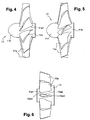
- the first means (11) is thus the axial compressor represented in FIGS. Figures 4 and 5 . It comprises a cylindrical body (11b) receiving on its periphery a plurality of blades (11a), made for example of aluminum, and front portion (11c) in the form of ogive. Said blades are treated on the surface of their underside by glass-ball blasting, this treatment having the function of hardening the corresponding surface to restore a creep created by the rotation of the rotor compressor and avoiding the deformation of the speed triangles on the blades.
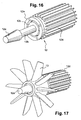
- the axial compressor is thus mounted on a conical axis (12a) to the engine group illustrated figure 16 .
- Said blades (11a) have a helical configuration with facing base profiles (11a1) of two diverging adjacent blades to improve the flow of air velocity.
- the calculation of the speed triangles of the blades is designed in such a way that it produces a high speed axial cylindrical air flow.
- the distribution of the air veins along the blade remains constant, on the same axis, so as not to disturb the air mass in general.
- the motor group (12) illustrated figure 16 thus comprises a shaft (12b) associated with the motor (12c) and protective casing (12d), a fixing flange (12e) of the motor.
- the shaft (12b) has a conical head (12a) for receiving support of the axial compressor (11).
- the connection of the axial compressor (11) to said conical portion is established in any suitable manner, the axial compressor being arranged complementary to fit.
- the second means (13) is the axial diffuser stator which is fixed and secured to the casing (10) by any appropriate connecting means. This second means (13) is located on the shaft portion (12c) between the attachment flange (12e) and the conical portion (12a).
- the diffuser stator comprises 10 blades (13a) for example of aluminum.
- the connection with the envelope (11) is effected by the end of the blades (13a).
- These blades (13a) are arranged in the extension of the blades (11a) formed on the compressor, but unlike these which have a helical configuration, the blades (13a) are arranged in the longitudinal axial direction of the axial stator stator. They have a symmetrical configuration with a progressive entry (13a1), and a second part (13a2) degressive, so as to form a teardrop profile.
- the examination of the two successive blades shows an entry of convergent profiles, then out of divergent profiles with an intermediate zone of narrowing with a neck (13a3).
- the front configuration in the first section of the blades allows an acceleration of the air flow and its speed, while the second part causes a significant drop in speed and contributes to the elevation of the pressure gradient.
- the folded geometrical shape of the blades (13a) gives a suitable orientation to the flow of air before admission to the following means, namely the static centrifugal compressor.
- This axial stator stator comprises plenums located upstream and downstream of itself, these means not being represented. The purpose of these chambers is to create a static pressure higher than the atmospheric pressure.
- This compressor (14) comprises a tubular body (14a) fitting around the engine block (12) and receiving according to a particular characteristic two sets of primary (14b) and secondary (14c) blades of different characteristics.
- the first series of blades (14b) comprises five blades arranged helically with geometry and variable pitch.
- These primary blades (14b) are developed so as to make a complete revolution around the receiving body (14a) in the configuration shown figure 9 .
- Said blades are initially parallel to each other in a pre-established space to allow positioning of the other series of secondary blades (14c) established at a much lower amplitude.
- Said secondary blades have a twisted configuration corresponding to the starting profile of the primary blades (14b), said blades (14c) being of less length in a ratio of 1 to 2 or 1 to 3.
- the centrifugal compressor statically, one distinguishes the positioning of the set of blades (14b-14c) arranged alternately with an identical spacing.
- the other end of the static centrifugal compressor only shows the ends of the primary blades. There is therefore a tightening of the space established between the successive blades (14b) creating the swirling flow.
- the inlet portions of the blades (14b-14c) are all in the longitudinal axial direction of the body, while the rear outlet ends of the primary blades are in a radial plane. It should also be noted that, to facilitate the circulation of the air fluid, the front and rear ends of all types of blades are tapered.
- each side of the blade is concave without special surface treatment.
- the static centrifugal compressor (14) makes it possible to transform the axial air flow coming from the means (13) into a rotational flow in order to accelerate it, while maintaining the static pressure established at the outlet of the diffuser stator. axial (13).
- Centrifugation is achieved by reversing the axial airflow along the blades and combining the swirling effects given by the different types of blades.
- the blades are constructed by projecting several unregulated surfaces according to the development of velocity triangles on the generatrix of the center of mass and the inertial center of each surface. These surfaces are then projected by winding on the final surface of each blade, to give a gyratory effect to the flow of air.
- the rotational flow is created, there is an increase in pressure on the surfaces, due to the centrifugal force created by the winding of the flow and the restreatment of the convergent duct between the bearing surfaces.
- the static pressure fluctuates as a function of the temperature rise throughout the journey.
- the characteristics of the fourth means (15) constituted by the axial diffuser rectifier shown in FIG. figure 10 The latter is located in axial extension of the means (14). It is constituted by a hollow cylindrical body (15a) capable of surrounding the motor unit (12c), by circulating ambient air.
- the axial diffuser rectifier On its periphery, the axial diffuser rectifier has a plurality of blades (15b) for example of aluminum 14 in number, arranged in a curvilinear configuration.
- the blades in the entrance zone have a range separation distance smaller than that existing at the rear end of said blades, creating a divergent effect, and the orientation of the blades at the rear end is in the longitudinal axis of the rectifier.
- the air inlet area from the means (14) is set to be an extension of the air outlet from the means (14).
- This means (15) is intended to straighten the vortex flow in axial flow and to slightly relax the pressure, in order to lower the temperature of the circulating air before admission into the sixth means (17) constituted by a vortex.
- the rectifier (15) is fixed in the envelope (10) by being fixed in any suitable manner.
- This axial diffuser rectifier is capable of cooperating and allowing the positioning and fitting of a fifth means (16) constituted by a transfer valve. It has a cylindrical body (16a) coming into the body (15a) of the rectifier (15), and it has a flange (16b) projecting cylindrical configuration.
- This ring-shaped collar is arranged with a plurality of lights (16c) allowing a passage and an air flow in the body (16a).
- On the ring (16b) is reported and positioned a ring (20) of complementary shape may be rotated angularly relative to said ring (16b).
- the ring itself has solid parts (20a) in the form of a cover which have shapes and dimensions complementary to the slots (16c) for closing them in whole or in part according to the position of the ring on the ring (16b). ).
- Adjusting means (21) and driving the ring on the ring gear is thus disposed on the body of the rectifier (15) to allow the appropriate angular orientation of the transfer valve.
- the sixth means (17) constituted by a vortex.
- This corresponds to the cylindrical disc (17a) hollow in its central part and receiving a plurality of blades (17b) for example of aluminum, 10 in number for example. These blades are arranged in a star configuration with a truncated cone.
- This vortex has the function of giving a stable and constant speed to the flow of air by a rotational movement between the blades, and it prepares the transfer of air flow produced in the expansion chamber (18) producing the cold disposed downstream. It has a cylindrical configuration with a nose (18a) ogive.
- the air conditioning thus constituted by all these means allows the production of hot or cold air according to temperature ranges adapted according to the applications of the invention, and this, thanks to the combination of the circulatory effects of air given by the various means described.
- the power unit and the transfer valve and their controls are connected to a computer-controlled digital card via an RS232 or other socket.
- the air conditioning according to the invention responds to the various problems posed.
- the configuration (11) of these various components and means and the number of blades is given as an example in the context of an optimization of operation of the air conditioner.
Landscapes
- Engineering & Computer Science (AREA)
- Mechanical Engineering (AREA)
- General Engineering & Computer Science (AREA)
- Physics & Mathematics (AREA)
- Thermal Sciences (AREA)
- Structures Of Non-Positive Displacement Pumps (AREA)
- Air Conditioning Control Device (AREA)
- Wind Motors (AREA)
Claims (13)
- Klimagerät, dadurch gekennzeichnet, dass es - nacheinander in einem Aufnahmemantel (10) angeordnet - eine erste Einrichtung (11) in Form eines Axialverdichters umfasst, der an seinem Rand mit Flügeln (11a) versehen ist und durch ein integriertes Motoraggregat (12) gespeist wird, das die Luftumwälzung mit einer gegebenen Geschwindigkeit bewirkt, dann eine zweite Einrichtung (13) in Form eines axialen Gleichrichter-Stators, der die Aufgabe hat, einen statischen Druck zu schaffen, der höher ist als der atmosphärische Druck, und den Luftstrom in eine dritte Einrichtung (14) in Form eines statischen Radialverdichters zu übertragen, der die Aufgabe hat, einen Rotationsstrom mit einem - abhängig von der Temperaturerhöhung entlang des Stroms - schwankenden statischen Druck zu erzeugen, wobei der Luftstrom in eine vierte Einrichtung (15) geleitet wird, die aus einem axialen Diffusor-Gleichrichter besteht, wobei der besagte Gleichrichter für die Raumluftzirkulation innen hohl ist und außen die Funktion hat, den Wirbelstrom in einen Axialstrom gleichzurichten und den Druck zu mindern, und dass eine fünfte Einrichtung (16) bestehend aus einem Transferventil sich um die vierte Einrichtung herum anpasst, um die Passage von Heißluft - mit Zufligung von Raumluft - zu regulieren oder nicht, und dass eine sechste Einrichtung (17) bestehend aus einem Wirbel die Beschleunigung des Luftstroms in einem Wirbeleffekt ermöglicht, bevor dieser in eine siebte Einrichtung (18) gelangt, die aus einer die Kälte produzierenden Expansionskammer besteht, und in den finalen Luftverteiler mit gewählten Temperaturbedingungen geleitet wird,
und dass sämtliche Einrichtungen (11, 12, 13, 14, 15, 16, 17, 18) in einem Schutz- und Verbindungsmantel (10) angeordnet sind. - Klimagerät nach Anspruch 1, dadurch gekennzeichnet, dass die erste Einrichtung (11) ein Axialverdichter mit einem zylindrischen Körper (11b) ist, der an seinem Rand mehrere Flügel (11a) aufnimmt und im vorderen Teil (11c) sprengkopfartig ausgebildet ist, wobei der Axialverdichter auf einer konischen Achse (12a) des Motoraggregats (12) angebracht ist und die besagten Flügel (11a) als Luftschraube mit einander zugewandten Basisprofilen (11a1) von zwei divergierenden angrenzenden Flügeln konfiguriert sind.
- Klimagerät nach den Ansprüchen 1 und 2, dadurch gekennzeichnet, dass das Motoraggregat (12) eine mit dem Motor (12c) und Schutzgehäuse (12d) verbundene Welle (12b) und einen Befestigungsflansch (12e) des Motors umfasst und dass die Welle (12b) an ihrem Ende einen kegelförmigen Kopf (12a) für die tragende Aufnahme des Axialverdichters (11) aufweist, wobei die Verbindung des Axialverdichters (11) auf dem besagten konischen Teil in zweckmäßiger Weise ausgebildet ist.
- Klimagerät nach Anspruch 3, dadurch gekennzeichnet, dass die zweite Einrichtung (13) ein axialer Diffusor-Stator ist, der mit dem Mantel (10) fest verbunden ist, wobei die zweite Einrichtung (13) sich am Wellenteil (12c) zwischen dem Befestigungsflansch (12e) und dem konischen Teil (12a) befindet, und dass sie Flügel (13a) umfasst, die in der Verlängerung der Kompressorflügel (11a) angeordnet sind, wobei die Flügel (13a) aber im Gegensatz zu jenen, die als Luftschraube konfiguriert sind, in der axialen Längsrichtung des axialen Diffusor-Stators angeordnet sind.
- Klimagerät nach Anspruch 4, dadurch gekennzeichnet, dass die Flügel (13a) eine symmetrische Konfiguration haben mit einem progressiven Eintritt (13a1) und einem zweiten degressiven Teil (13a2), so dass ein Wassertropfenprofil gebildet wird, und dass die Lage von zwei aufeinander folgenden Flügeln einen Eintritt aus konvergierenden, dann am Austritt aus divergierenden Profilen mit einem verengten Zwischenbereich mit einem Hals (13a3) beschreibt.
- Klimagerät nach Anspruch 5, dadurch gekennzeichnet, dass der axiale Gleichrichter-Stator mit einer Beruhigungskammer in Zu- und Abstrom ausgebildet ist, die die Aufgabe hat, einen statischen Druck aufzubauen, der höher ist als der atmosphärische Druck.
- Klimagerät nach Anspruch 2, dadurch gekennzeichnet, dass die dritte Einrichtung (14) aus einem statischen Radialverdichter besteht, der einen rohrartigen Körper (14a) besitzt, der sich um den Motorblock (12) herum anpasst und nach einem besonderen Merkmal zwei Reihen von Primärflügeln (14b) und Sekundärflügeln (14c) mit unterschiedlichen Eigenheiten aufnimmt.
- Klimagerät nach Anspruch 7, dadurch gekennzeichnet, dass die dritte Einrichtung eine erste Flügelreihe (14b) mit fünf Flügeln umfasst, die schraubenartig mit variabler Geometrie und Steigung angeordnet sind, wobei diese ersten Flügel (14b) so ausgelegt sind, dass sie den aufnehmenden Körper (14a) ganz umrunden, und dass die besagten Flügel anfänglich in einem vorgegebenen Abstand zueinander parallel sind, um die Positionierung der anderen Reihe aus Sekundärflügeln (14c) zu ermöglichen, die eine deutlich geringere Amplitude aufweisen, und dass die besagten Sekundärflügel eine dem Anfangsprofil der Primärflügel (14b) entsprechende verdrehte Form haben, wobei die besagten Flügel (14c) weniger lang sind.
- Klimagerät nach Anspruch 8, dadurch gekennzeichnet, dass die Eintrittsteile der Flügel (14b-14c) alle in der Längsaxialrichtung des Körpers verlaufen, während sich die Enden am hinteren Austritt der Primärflügel auf einer radialen Ebene befinden, und dass die Oberfläche beiderseits der Flügel konkav ist.
- Klimagerät nach Anspruch 2, dadurch gekennzeichnet, dass die vierte Einrichtung (15) aus einem axialen Diffusor-Gleichrichter besteht, der sich in axialer Verlängerung der Einrichtung (14) befindet, und dass er aus einem hohlen zylindrischen Körper (15a) besteht, der geeignet ist, den Motorblock (12c) zu umgeben und dabei Raumluft zirkulieren zu lassen, und dass der axiale Diffusor-Gleichrichter mehrere Flügel (15b) aufweist, die in einer kurvenförmiges Konfiguration angeordnet sind.
- Klimagerät nach Anspruch 10, dadurch gekennzeichnet, dass die Flügel am Eintrittsbereich geringer beabstandet sind als an ihrem hinteren Ende, wodurch ein divergierender Effekt entsteht, und dass die Flügel am hinteren Ende axial zur Längsachse des Gleichrichters ausgerichtet sind, und dass der Eintrittsbereich der von der Einrichtung (14) kommenden Luft so ausgebildet ist, um sich in der Verlängerung des von der Einrichtung (14) kommenden Luftaustritts zu befinden.
- Klimagerät nach einem der Ansprüche 10 und 11, dadurch gekennzeichnet, dass der axiale Diffusor-Gleichrichter zum Zusammenwirken geeignet ist und das Positionieren und Aufstecken einer fünften Einrichtung (16) ermöglicht, die aus einem Transferventil besteht, und dass diese Einrichtung (16) einen zylindrischen Körper (16a), der in den Körper (15a) des Gleichrichters (15) gesteckt wird, und einen vorstehenden Bund (16b) mit zylindrischer Form aufweist, und dass der Bund in Kranzform mit mehreren Schlitzen (16c) ausgebildet ist, die eine Passage und den Umlauf von Luft im Körper (16a) ermöglichen, und dass am Kranz (16b) ein Ring (20) mit komplementärer Form angesetzt und positioniert ist, der im Winkel zu dem besagten Kranz (16b) geschwenkt werden kann, und dass der Ring selbst vollwandige Teile (20a) als Abdeckung aufweist, die komplementäre Formen und Abmessungen zu den Schlitzen (16c) haben, um sie je nach Position des Rings am Kranz (16b) ganz oder teilweise zu verschließen, und dass eine Einrichtung (21) für die Regulierung und Mitführung des Rings am Kranz so am Körper des Gleichrichters (15) angeordnet ist, um die zweckmäßige Winkelausrichtung des Transferventils zu ermöglichen.
- Klimagerät nach Anspruch 2, dadurch gekennzeichnet, dass die sechste Einrichtung (17) aus einem Wirbel mit einer zylindrischen Scheibe (17a) besteht, die in ihrem mittleren Teil hohl ist und mehrere Flügel (17b) aufnimmt, und dass die Flügel sternförmig mit einer kegelstumpfartigen Konfiguration angeordnet sind, und dass der Wirbel die Aufgabe hat, dem Luftstrom durch eine Rotationsbewegung zwischen den Flügeln eine stabile und konstante Geschwindigkeit zu geben und den Transfer des produzierten Luftstroms in die nachgeordnete Expansionskammer (18) vorzubereiten.
Applications Claiming Priority (2)
| Application Number | Priority Date | Filing Date | Title |
|---|---|---|---|
| FR0752698A FR2911386B1 (fr) | 2007-01-16 | 2007-01-16 | Appareil de conditionnement d'air muni d'un compresseur et d'un vortex |
| PCT/FR2008/050069 WO2008099119A1 (fr) | 2007-01-16 | 2008-01-15 | Appareil de conditionnement d'air muni d'un compresseur et d'un vortex |
Publications (2)
| Publication Number | Publication Date |
|---|---|
| EP2122178A1 EP2122178A1 (de) | 2009-11-25 |
| EP2122178B1 true EP2122178B1 (de) | 2011-11-16 |
Family
ID=38514231
Family Applications (1)
| Application Number | Title | Priority Date | Filing Date |
|---|---|---|---|
| EP08761940A Not-in-force EP2122178B1 (de) | 2007-01-16 | 2008-01-15 | Mit einem kompressor und einer wirbelvorrichtung ausgestattete klimaanlage |
Country Status (6)
| Country | Link |
|---|---|
| US (1) | US20100172750A1 (de) |
| EP (1) | EP2122178B1 (de) |
| JP (1) | JP2010515862A (de) |
| AT (1) | ATE533945T1 (de) |
| FR (1) | FR2911386B1 (de) |
| WO (1) | WO2008099119A1 (de) |
Families Citing this family (10)
| Publication number | Priority date | Publication date | Assignee | Title |
|---|---|---|---|---|
| JP5443023B2 (ja) * | 2009-03-09 | 2014-03-19 | 株式会社医器研 | コンプレッサおよび酸素濃縮装置 |
| DE112014003121T5 (de) * | 2013-07-04 | 2016-04-07 | Ihi Corporation | Verdichterlaufrad, Radialverdichter, Bearbeitungsverfahren für ein Verdichterlaufrad und Bearbeitungsvorrichtung für ein Verdichterlaufrad |
| WO2016201455A1 (en) * | 2015-06-12 | 2016-12-15 | Ac (Macao Commercial Offshore) Limited | Axial fan blower |
| US10676197B2 (en) * | 2017-01-04 | 2020-06-09 | Goodrich Corporation | Aspirator |
| CN110081014B (zh) * | 2019-04-26 | 2021-04-06 | 哈尔滨工程大学 | 一种叶片起旋的离心式涡流管 |
| CN110566480A (zh) * | 2019-09-16 | 2019-12-13 | 珠海格力电器股份有限公司 | 外转子风机及空调机组 |
| PL240519B1 (pl) * | 2020-01-31 | 2022-04-19 | Dac Spolka Z Ograniczona Odpowiedzialnoscia | Agregat chłodniczy z dynamicznym chłodzeniem powietrza i element roboczy agregatu |
| CN113566410B (zh) * | 2021-07-26 | 2024-12-03 | 珠海格力电器股份有限公司 | 一种扫风叶片、空调器及其控制方法 |
| KR102773921B1 (ko) * | 2022-03-08 | 2025-02-27 | 이동규 | 람젯 기류발생기 |
| WO2026024384A1 (en) * | 2024-07-23 | 2026-01-29 | Danfoss A/S | Refrigerant compressor including configuration of axial and centrifugal stages |
Family Cites Families (13)
| Publication number | Priority date | Publication date | Assignee | Title |
|---|---|---|---|---|
| US1952281A (en) * | 1931-12-12 | 1934-03-27 | Giration Des Fluides Sarl | Method and apparatus for obtaining from alpha fluid under pressure two currents of fluids at different temperatures |
| US2435236A (en) * | 1943-11-23 | 1948-02-03 | Westinghouse Electric Corp | Superacoustic compressor |
| BE643182A (de) * | 1963-01-30 | |||
| US4051689A (en) * | 1976-06-08 | 1977-10-04 | Macdonald Ronald A | Air separating apparatus |
| JPS6066827U (ja) * | 1983-10-17 | 1985-05-11 | いすゞ自動車株式会社 | 過給機付エンジンの吸気冷却装置 |
| JPS6115466U (ja) * | 1984-07-02 | 1986-01-29 | 株式会社 日本メデイツクス | 熱交換器 |
| JPS6134063U (ja) * | 1984-07-31 | 1986-03-01 | 三菱重工業株式会社 | 冷却装置 |
| US4594084A (en) * | 1985-07-15 | 1986-06-10 | Astrl Corporation | Air conditioning system |
| CH687637A5 (de) * | 1993-11-04 | 1997-01-15 | Micronel Ag | Axialkleinventilator. |
| DE19525699A1 (de) * | 1995-07-14 | 1997-01-16 | Bmw Rolls Royce Gmbh | Tandem-Schaufelgitter |
| FR2808568B1 (fr) * | 2000-05-05 | 2002-08-02 | Valeo Thermique Moteur Sa | Ventilateur pour vehicule automobile muni d'aubes directrices |
| AU2003278524A1 (en) * | 2003-10-24 | 2005-05-11 | Honeywell International Inc | Sector-divided turbine assembly with axial piston variable-geometry mechanism |
| US7195456B2 (en) * | 2004-12-21 | 2007-03-27 | United Technologies Corporation | Turbine engine guide vane and arrays thereof |
-
2007
- 2007-01-16 FR FR0752698A patent/FR2911386B1/fr not_active Expired - Fee Related
-
2008
- 2008-01-15 WO PCT/FR2008/050069 patent/WO2008099119A1/fr not_active Ceased
- 2008-01-15 AT AT08761940T patent/ATE533945T1/de active
- 2008-01-15 US US12/523,384 patent/US20100172750A1/en not_active Abandoned
- 2008-01-15 EP EP08761940A patent/EP2122178B1/de not_active Not-in-force
- 2008-01-15 JP JP2009545986A patent/JP2010515862A/ja not_active Ceased
Also Published As
| Publication number | Publication date |
|---|---|
| FR2911386A1 (fr) | 2008-07-18 |
| JP2010515862A (ja) | 2010-05-13 |
| FR2911386B1 (fr) | 2009-03-06 |
| WO2008099119A1 (fr) | 2008-08-21 |
| EP2122178A1 (de) | 2009-11-25 |
| ATE533945T1 (de) | 2011-12-15 |
| US20100172750A1 (en) | 2010-07-08 |
Similar Documents
| Publication | Publication Date | Title |
|---|---|---|
| EP2122178A1 (de) | Mit einem kompressor und einer wirbelvorrichtung ausgestattete klimaanlage | |
| EP2657531A1 (de) | Axiallüfter mit einem zentripetal wirkenden Nachleitrad, dass eine Nabe mit geringem Durchmesser umfasst | |
| CA2722077C (fr) | Prelevement d'air centripete dans un rotor de compresseur d'une turbomachine | |
| EP1881179B1 (de) | Wandbelüftungssystem für die Brennkammer einer Strömungsmaschine | |
| CA2722162C (fr) | Rotor de compresseur d'une turbomachine comportant des moyens de prelevement d'air centripete | |
| FR2641328A1 (fr) | Montage de moteur a turbine muni d'aubes directrices de sortie montees a l'arriere | |
| FR2690482A1 (fr) | Circuit de ventilation des disques de compresseurs et de turbines. | |
| EP1882826A1 (de) | System zur Lüftung eines Hohlraums stromabwärts eines Zentrifugalverdichterrads | |
| EP1881181A2 (de) | Belüftung eines Hohlraums hinter dem Rad eines Radialverdichters in einer Strömungsmaschine | |
| EP4168658B1 (de) | Flugzeugturbomaschine mit wiedergewonnenem zyklus | |
| EP3517444B1 (de) | Mast eines luftfahrzeugs, der einen koaxialen wärmetauscher umfasst | |
| EP4168659B1 (de) | Flugzeugturbomaschine mit wiedergewonnenem zyklus | |
| EP4081698A1 (de) | Turbine, die einen inneren sekundärraum aufweist, der mit rippen zum korrigieren der kreiselbewegung eines luftstroms ausgestattet ist | |
| CA3024433A1 (fr) | Mat d'un ensemble propulsif | |
| WO2020109705A1 (fr) | Turboréacteur à double flux comprenant un cône de sortie refroidi par son flux secondaire | |
| FR2549310A1 (fr) | Combinaison d'un diffuseur de ventilateur et d'un collecteur de gaz pour systemes de refroidissement de machines dynamoelectriques | |
| EP3447271B1 (de) | Heizsystem für sekundäre düse vom konvergierenden/divergierenden typ | |
| WO2024246459A1 (fr) | Turbomachine d'aeronef a cycle recupere | |
| EP3290657B1 (de) | Stator mit verstellbaren schaufeln fürden kompressor eines axialen gasturbinenmotors | |
| EP2799666B1 (de) | Spiralgehäuse mit zwei Volumina für Gasturbine | |
| WO2021191534A1 (fr) | Ensemble d'anneau et de distributeur de turbine de turbomachine | |
| FR3166329A1 (fr) | Groupe moto-ventilateur avec une entrée d’air et une sortie d’air axiales. | |
| FR3002287A1 (fr) | Procede de melange entre un ecoulement primaire et un ecoulement secondaire dans une turbomachine, dispositif et turbomachine correspondants | |
| FR3166409A1 (fr) | Groupe moto-ventilateur avec une entrée d’air et une sortie d’air axiales à faibles nuisances sonores. | |
| FR3025260B1 (fr) | Compresseur centrifuge a resistance amelioree |
Legal Events
| Date | Code | Title | Description |
|---|---|---|---|
| PUAI | Public reference made under article 153(3) epc to a published international application that has entered the european phase |
Free format text: ORIGINAL CODE: 0009012 |
|
| 17P | Request for examination filed |
Effective date: 20090709 |
|
| AK | Designated contracting states |
Kind code of ref document: A1 Designated state(s): AT BE BG CH CY CZ DE DK EE ES FI FR GB GR HR HU IE IS IT LI LT LU LV MC MT NL NO PL PT RO SE SI SK TR |
|
| DAX | Request for extension of the european patent (deleted) | ||
| GRAP | Despatch of communication of intention to grant a patent |
Free format text: ORIGINAL CODE: EPIDOSNIGR1 |
|
| GRAS | Grant fee paid |
Free format text: ORIGINAL CODE: EPIDOSNIGR3 |
|
| GRAA | (expected) grant |
Free format text: ORIGINAL CODE: 0009210 |
|
| AK | Designated contracting states |
Kind code of ref document: B1 Designated state(s): AT BE BG CH CY CZ DE DK EE ES FI FR GB GR HR HU IE IS IT LI LT LU LV MC MT NL NO PL PT RO SE SI SK TR |
|
| REG | Reference to a national code |
Ref country code: GB Ref legal event code: FG4D Free format text: NOT ENGLISH |
|
| REG | Reference to a national code |
Ref country code: CH Ref legal event code: EP |
|
| REG | Reference to a national code |
Ref country code: IE Ref legal event code: FG4D Free format text: LANGUAGE OF EP DOCUMENT: FRENCH |
|
| REG | Reference to a national code |
Ref country code: DE Ref legal event code: R096 Ref document number: 602008011433 Country of ref document: DE Effective date: 20120112 |
|
| REG | Reference to a national code |
Ref country code: NL Ref legal event code: VDEP Effective date: 20111116 |
|
| REG | Reference to a national code |
Ref country code: DE Ref legal event code: R082 Ref document number: 602008011433 Country of ref document: DE Representative=s name: DREISS PATENTANWAELTE, DE Ref country code: DE Ref legal event code: R082 Ref document number: 602008011433 Country of ref document: DE Representative=s name: DREISS PATENTANWAELTE PARTNERSCHAFT, DE Ref country code: DE Ref legal event code: R082 Ref document number: 602008011433 Country of ref document: DE Representative=s name: DREISS PATENTANWAELTE PARTG MBB, DE |
|
| LTIE | Lt: invalidation of european patent or patent extension |
Effective date: 20111116 |
|
| PG25 | Lapsed in a contracting state [announced via postgrant information from national office to epo] |
Ref country code: IS Free format text: LAPSE BECAUSE OF FAILURE TO SUBMIT A TRANSLATION OF THE DESCRIPTION OR TO PAY THE FEE WITHIN THE PRESCRIBED TIME-LIMIT Effective date: 20120316 Ref country code: LT Free format text: LAPSE BECAUSE OF FAILURE TO SUBMIT A TRANSLATION OF THE DESCRIPTION OR TO PAY THE FEE WITHIN THE PRESCRIBED TIME-LIMIT Effective date: 20111116 Ref country code: NO Free format text: LAPSE BECAUSE OF FAILURE TO SUBMIT A TRANSLATION OF THE DESCRIPTION OR TO PAY THE FEE WITHIN THE PRESCRIBED TIME-LIMIT Effective date: 20120216 |
|
| PGFP | Annual fee paid to national office [announced via postgrant information from national office to epo] |
Ref country code: FR Payment date: 20120312 Year of fee payment: 5 |
|
| PG25 | Lapsed in a contracting state [announced via postgrant information from national office to epo] |
Ref country code: NL Free format text: LAPSE BECAUSE OF FAILURE TO SUBMIT A TRANSLATION OF THE DESCRIPTION OR TO PAY THE FEE WITHIN THE PRESCRIBED TIME-LIMIT Effective date: 20111116 Ref country code: SI Free format text: LAPSE BECAUSE OF FAILURE TO SUBMIT A TRANSLATION OF THE DESCRIPTION OR TO PAY THE FEE WITHIN THE PRESCRIBED TIME-LIMIT Effective date: 20111116 Ref country code: SE Free format text: LAPSE BECAUSE OF FAILURE TO SUBMIT A TRANSLATION OF THE DESCRIPTION OR TO PAY THE FEE WITHIN THE PRESCRIBED TIME-LIMIT Effective date: 20111116 Ref country code: GR Free format text: LAPSE BECAUSE OF FAILURE TO SUBMIT A TRANSLATION OF THE DESCRIPTION OR TO PAY THE FEE WITHIN THE PRESCRIBED TIME-LIMIT Effective date: 20120217 Ref country code: LV Free format text: LAPSE BECAUSE OF FAILURE TO SUBMIT A TRANSLATION OF THE DESCRIPTION OR TO PAY THE FEE WITHIN THE PRESCRIBED TIME-LIMIT Effective date: 20111116 Ref country code: PL Free format text: LAPSE BECAUSE OF FAILURE TO SUBMIT A TRANSLATION OF THE DESCRIPTION OR TO PAY THE FEE WITHIN THE PRESCRIBED TIME-LIMIT Effective date: 20111116 Ref country code: PT Free format text: LAPSE BECAUSE OF FAILURE TO SUBMIT A TRANSLATION OF THE DESCRIPTION OR TO PAY THE FEE WITHIN THE PRESCRIBED TIME-LIMIT Effective date: 20120316 Ref country code: HR Free format text: LAPSE BECAUSE OF FAILURE TO SUBMIT A TRANSLATION OF THE DESCRIPTION OR TO PAY THE FEE WITHIN THE PRESCRIBED TIME-LIMIT Effective date: 20111116 |
|
| PGFP | Annual fee paid to national office [announced via postgrant information from national office to epo] |
Ref country code: DE Payment date: 20120315 Year of fee payment: 5 |
|
| REG | Reference to a national code |
Ref country code: IE Ref legal event code: FD4D |
|
| PG25 | Lapsed in a contracting state [announced via postgrant information from national office to epo] |
Ref country code: CY Free format text: LAPSE BECAUSE OF FAILURE TO SUBMIT A TRANSLATION OF THE DESCRIPTION OR TO PAY THE FEE WITHIN THE PRESCRIBED TIME-LIMIT Effective date: 20111116 |
|
| BERE | Be: lapsed |
Owner name: GENIUS Effective date: 20120131 |
|
| PG25 | Lapsed in a contracting state [announced via postgrant information from national office to epo] |
Ref country code: CZ Free format text: LAPSE BECAUSE OF FAILURE TO SUBMIT A TRANSLATION OF THE DESCRIPTION OR TO PAY THE FEE WITHIN THE PRESCRIBED TIME-LIMIT Effective date: 20111116 Ref country code: SK Free format text: LAPSE BECAUSE OF FAILURE TO SUBMIT A TRANSLATION OF THE DESCRIPTION OR TO PAY THE FEE WITHIN THE PRESCRIBED TIME-LIMIT Effective date: 20111116 Ref country code: DK Free format text: LAPSE BECAUSE OF FAILURE TO SUBMIT A TRANSLATION OF THE DESCRIPTION OR TO PAY THE FEE WITHIN THE PRESCRIBED TIME-LIMIT Effective date: 20111116 Ref country code: IE Free format text: LAPSE BECAUSE OF FAILURE TO SUBMIT A TRANSLATION OF THE DESCRIPTION OR TO PAY THE FEE WITHIN THE PRESCRIBED TIME-LIMIT Effective date: 20111116 Ref country code: EE Free format text: LAPSE BECAUSE OF FAILURE TO SUBMIT A TRANSLATION OF THE DESCRIPTION OR TO PAY THE FEE WITHIN THE PRESCRIBED TIME-LIMIT Effective date: 20111116 Ref country code: BG Free format text: LAPSE BECAUSE OF FAILURE TO SUBMIT A TRANSLATION OF THE DESCRIPTION OR TO PAY THE FEE WITHIN THE PRESCRIBED TIME-LIMIT Effective date: 20120216 |
|
| PG25 | Lapsed in a contracting state [announced via postgrant information from national office to epo] |
Ref country code: MC Free format text: LAPSE BECAUSE OF NON-PAYMENT OF DUE FEES Effective date: 20120131 Ref country code: IT Free format text: LAPSE BECAUSE OF FAILURE TO SUBMIT A TRANSLATION OF THE DESCRIPTION OR TO PAY THE FEE WITHIN THE PRESCRIBED TIME-LIMIT Effective date: 20111116 Ref country code: RO Free format text: LAPSE BECAUSE OF FAILURE TO SUBMIT A TRANSLATION OF THE DESCRIPTION OR TO PAY THE FEE WITHIN THE PRESCRIBED TIME-LIMIT Effective date: 20111116 |
|
| REG | Reference to a national code |
Ref country code: CH Ref legal event code: PL |
|
| REG | Reference to a national code |
Ref country code: AT Ref legal event code: MK05 Ref document number: 533945 Country of ref document: AT Kind code of ref document: T Effective date: 20111116 |
|
| PLBE | No opposition filed within time limit |
Free format text: ORIGINAL CODE: 0009261 |
|
| STAA | Information on the status of an ep patent application or granted ep patent |
Free format text: STATUS: NO OPPOSITION FILED WITHIN TIME LIMIT |
|
| 26N | No opposition filed |
Effective date: 20120817 |
|
| GBPC | Gb: european patent ceased through non-payment of renewal fee |
Effective date: 20120216 |
|
| PG25 | Lapsed in a contracting state [announced via postgrant information from national office to epo] |
Ref country code: LI Free format text: LAPSE BECAUSE OF NON-PAYMENT OF DUE FEES Effective date: 20120131 Ref country code: CH Free format text: LAPSE BECAUSE OF NON-PAYMENT OF DUE FEES Effective date: 20120131 |
|
| REG | Reference to a national code |
Ref country code: DE Ref legal event code: R097 Ref document number: 602008011433 Country of ref document: DE Effective date: 20120817 |
|
| PG25 | Lapsed in a contracting state [announced via postgrant information from national office to epo] |
Ref country code: BE Free format text: LAPSE BECAUSE OF NON-PAYMENT OF DUE FEES Effective date: 20120131 |
|
| PG25 | Lapsed in a contracting state [announced via postgrant information from national office to epo] |
Ref country code: GB Free format text: LAPSE BECAUSE OF NON-PAYMENT OF DUE FEES Effective date: 20120216 Ref country code: AT Free format text: LAPSE BECAUSE OF FAILURE TO SUBMIT A TRANSLATION OF THE DESCRIPTION OR TO PAY THE FEE WITHIN THE PRESCRIBED TIME-LIMIT Effective date: 20111116 |
|
| PG25 | Lapsed in a contracting state [announced via postgrant information from national office to epo] |
Ref country code: ES Free format text: LAPSE BECAUSE OF FAILURE TO SUBMIT A TRANSLATION OF THE DESCRIPTION OR TO PAY THE FEE WITHIN THE PRESCRIBED TIME-LIMIT Effective date: 20120227 |
|
| PG25 | Lapsed in a contracting state [announced via postgrant information from national office to epo] |
Ref country code: FI Free format text: LAPSE BECAUSE OF FAILURE TO SUBMIT A TRANSLATION OF THE DESCRIPTION OR TO PAY THE FEE WITHIN THE PRESCRIBED TIME-LIMIT Effective date: 20111116 |
|
| PG25 | Lapsed in a contracting state [announced via postgrant information from national office to epo] |
Ref country code: MT Free format text: LAPSE BECAUSE OF FAILURE TO SUBMIT A TRANSLATION OF THE DESCRIPTION OR TO PAY THE FEE WITHIN THE PRESCRIBED TIME-LIMIT Effective date: 20111116 |
|
| REG | Reference to a national code |
Ref country code: FR Ref legal event code: ST Effective date: 20130930 |
|
| PG25 | Lapsed in a contracting state [announced via postgrant information from national office to epo] |
Ref country code: DE Free format text: LAPSE BECAUSE OF NON-PAYMENT OF DUE FEES Effective date: 20130801 |
|
| REG | Reference to a national code |
Ref country code: DE Ref legal event code: R119 Ref document number: 602008011433 Country of ref document: DE Effective date: 20130801 |
|
| PG25 | Lapsed in a contracting state [announced via postgrant information from national office to epo] |
Ref country code: FR Free format text: LAPSE BECAUSE OF NON-PAYMENT OF DUE FEES Effective date: 20130131 |
|
| PG25 | Lapsed in a contracting state [announced via postgrant information from national office to epo] |
Ref country code: TR Free format text: LAPSE BECAUSE OF FAILURE TO SUBMIT A TRANSLATION OF THE DESCRIPTION OR TO PAY THE FEE WITHIN THE PRESCRIBED TIME-LIMIT Effective date: 20111116 |
|
| PG25 | Lapsed in a contracting state [announced via postgrant information from national office to epo] |
Ref country code: LU Free format text: LAPSE BECAUSE OF NON-PAYMENT OF DUE FEES Effective date: 20120115 |
|
| PG25 | Lapsed in a contracting state [announced via postgrant information from national office to epo] |
Ref country code: HU Free format text: LAPSE BECAUSE OF FAILURE TO SUBMIT A TRANSLATION OF THE DESCRIPTION OR TO PAY THE FEE WITHIN THE PRESCRIBED TIME-LIMIT Effective date: 20080115 |