EP2122244B1 - Steuermodul für ein beleuchtungssystem, beleuchtungssystem und lichtmodul für ein beleuchtungssystem - Google Patents
Steuermodul für ein beleuchtungssystem, beleuchtungssystem und lichtmodul für ein beleuchtungssystem Download PDFInfo
- Publication number
- EP2122244B1 EP2122244B1 EP08702590.4A EP08702590A EP2122244B1 EP 2122244 B1 EP2122244 B1 EP 2122244B1 EP 08702590 A EP08702590 A EP 08702590A EP 2122244 B1 EP2122244 B1 EP 2122244B1
- Authority
- EP
- European Patent Office
- Prior art keywords
- module
- control module
- electrodes
- light
- lighting system
- Prior art date
- Legal status (The legal status is an assumption and is not a legal conclusion. Google has not performed a legal analysis and makes no representation as to the accuracy of the status listed.)
- Active
Links
Images


Classifications
-
- F—MECHANICAL ENGINEERING; LIGHTING; HEATING; WEAPONS; BLASTING
- F21—LIGHTING
- F21V—FUNCTIONAL FEATURES OR DETAILS OF LIGHTING DEVICES OR SYSTEMS THEREOF; STRUCTURAL COMBINATIONS OF LIGHTING DEVICES WITH OTHER ARTICLES, NOT OTHERWISE PROVIDED FOR
- F21V21/00—Supporting, suspending, or attaching arrangements for lighting devices; Hand grips
- F21V21/34—Supporting elements displaceable along a guiding element
- F21V21/35—Supporting elements displaceable along a guiding element with direct electrical contact between the supporting element and electric conductors running along the guiding element
-
- F—MECHANICAL ENGINEERING; LIGHTING; HEATING; WEAPONS; BLASTING
- F21—LIGHTING
- F21V—FUNCTIONAL FEATURES OR DETAILS OF LIGHTING DEVICES OR SYSTEMS THEREOF; STRUCTURAL COMBINATIONS OF LIGHTING DEVICES WITH OTHER ARTICLES, NOT OTHERWISE PROVIDED FOR
- F21V21/00—Supporting, suspending, or attaching arrangements for lighting devices; Hand grips
- F21V21/08—Devices for easy attachment to any desired place, e.g. clip, clamp, magnet
- F21V21/096—Magnetic devices
-
- F—MECHANICAL ENGINEERING; LIGHTING; HEATING; WEAPONS; BLASTING
- F21—LIGHTING
- F21V—FUNCTIONAL FEATURES OR DETAILS OF LIGHTING DEVICES OR SYSTEMS THEREOF; STRUCTURAL COMBINATIONS OF LIGHTING DEVICES WITH OTHER ARTICLES, NOT OTHERWISE PROVIDED FOR
- F21V23/00—Arrangement of electric circuit elements in or on lighting devices
- F21V23/04—Arrangement of electric circuit elements in or on lighting devices the elements being switches
-
- H—ELECTRICITY
- H01—ELECTRIC ELEMENTS
- H01R—ELECTRICALLY-CONDUCTIVE CONNECTIONS; STRUCTURAL ASSOCIATIONS OF A PLURALITY OF MUTUALLY-INSULATED ELECTRICAL CONNECTING ELEMENTS; COUPLING DEVICES; CURRENT COLLECTORS
- H01R25/00—Coupling parts adapted for simultaneous co-operation with two or more identical counterparts, e.g. for distributing energy to two or more circuits
- H01R25/14—Rails or bus-bars constructed so that the counterparts can be connected thereto at any point along their length
- H01R25/147—Low voltage devices, i.e. safe to touch live conductors
-
- H—ELECTRICITY
- H05—ELECTRIC TECHNIQUES NOT OTHERWISE PROVIDED FOR
- H05B—ELECTRIC HEATING; ELECTRIC LIGHT SOURCES NOT OTHERWISE PROVIDED FOR; CIRCUIT ARRANGEMENTS FOR ELECTRIC LIGHT SOURCES, IN GENERAL
- H05B39/00—Circuit arrangements or apparatus for operating incandescent light sources
-
- H—ELECTRICITY
- H05—ELECTRIC TECHNIQUES NOT OTHERWISE PROVIDED FOR
- H05B—ELECTRIC HEATING; ELECTRIC LIGHT SOURCES NOT OTHERWISE PROVIDED FOR; CIRCUIT ARRANGEMENTS FOR ELECTRIC LIGHT SOURCES, IN GENERAL
- H05B45/00—Circuit arrangements for operating light-emitting diodes [LED]
- H05B45/60—Circuit arrangements for operating LEDs comprising organic material, e.g. for operating organic light-emitting diodes [OLED] or polymer light-emitting diodes [PLED]
-
- H—ELECTRICITY
- H05—ELECTRIC TECHNIQUES NOT OTHERWISE PROVIDED FOR
- H05B—ELECTRIC HEATING; ELECTRIC LIGHT SOURCES NOT OTHERWISE PROVIDED FOR; CIRCUIT ARRANGEMENTS FOR ELECTRIC LIGHT SOURCES, IN GENERAL
- H05B47/00—Circuit arrangements for operating light sources in general, i.e. where the type of light source is not relevant
- H05B47/10—Controlling the light source
- H05B47/175—Controlling the light source by remote control
- H05B47/18—Controlling the light source by remote control via data-bus transmission
-
- F—MECHANICAL ENGINEERING; LIGHTING; HEATING; WEAPONS; BLASTING
- F21—LIGHTING
- F21Y—INDEXING SCHEME ASSOCIATED WITH SUBCLASSES F21K, F21L, F21S and F21V, RELATING TO THE FORM OR THE KIND OF THE LIGHT SOURCES OR OF THE COLOUR OF THE LIGHT EMITTED
- F21Y2105/00—Planar light sources
-
- F—MECHANICAL ENGINEERING; LIGHTING; HEATING; WEAPONS; BLASTING
- F21—LIGHTING
- F21Y—INDEXING SCHEME ASSOCIATED WITH SUBCLASSES F21K, F21L, F21S and F21V, RELATING TO THE FORM OR THE KIND OF THE LIGHT SOURCES OR OF THE COLOUR OF THE LIGHT EMITTED
- F21Y2115/00—Light-generating elements of semiconductor light sources
- F21Y2115/10—Light-emitting diodes [LED]
- F21Y2115/15—Organic light-emitting diodes [OLED]
-
- H—ELECTRICITY
- H05—ELECTRIC TECHNIQUES NOT OTHERWISE PROVIDED FOR
- H05B—ELECTRIC HEATING; ELECTRIC LIGHT SOURCES NOT OTHERWISE PROVIDED FOR; CIRCUIT ARRANGEMENTS FOR ELECTRIC LIGHT SOURCES, IN GENERAL
- H05B47/00—Circuit arrangements for operating light sources in general, i.e. where the type of light source is not relevant
- H05B47/10—Controlling the light source
- H05B47/175—Controlling the light source by remote control
- H05B47/198—Grouping of control procedures or address assignation to light sources
-
- H—ELECTRICITY
- H10—SEMICONDUCTOR DEVICES; ELECTRIC SOLID-STATE DEVICES NOT OTHERWISE PROVIDED FOR
- H10K—ORGANIC ELECTRIC SOLID-STATE DEVICES
- H10K59/00—Integrated devices, or assemblies of multiple devices, comprising at least one organic light-emitting element covered by group H10K50/00
- H10K59/90—Assemblies of multiple devices comprising at least one organic light-emitting element
-
- Y—GENERAL TAGGING OF NEW TECHNOLOGICAL DEVELOPMENTS; GENERAL TAGGING OF CROSS-SECTIONAL TECHNOLOGIES SPANNING OVER SEVERAL SECTIONS OF THE IPC; TECHNICAL SUBJECTS COVERED BY FORMER USPC CROSS-REFERENCE ART COLLECTIONS [XRACs] AND DIGESTS
- Y02—TECHNOLOGIES OR APPLICATIONS FOR MITIGATION OR ADAPTATION AGAINST CLIMATE CHANGE
- Y02B—CLIMATE CHANGE MITIGATION TECHNOLOGIES RELATED TO BUILDINGS, e.g. HOUSING, HOUSE APPLIANCES OR RELATED END-USER APPLICATIONS
- Y02B20/00—Energy efficient lighting technologies, e.g. halogen lamps or gas discharge lamps
- Y02B20/30—Semiconductor lamps, e.g. solid state lamps [SSL] light emitting diodes [LED] or organic LED [OLED]
Definitions
- the present invention relates to a control module for a lighting system.
- the invention also relates to a light module for a lighting system and to a lighting system.
- Lighting systems are generally known, e.g. lighting systems with LEDs or halogen lamps. It is also known to use elongated parallel extending electrodes, for example in form of cables or rods which are supplied with the supply voltage and on which the lamps are attached.
- the control element for switching on and off or for adjusting the brightness of such a lighting system is often central for all lamps and often remote of the system at a fixed place. Typically, the central control element is hidden and therefore not easily reachable by the user. Having a control unit in each light element, complicates its usage when a group of light elements should have the same properties, such as brightness and/or color.
- US 2003/179578 A1 discloses a conductor rail system with a control line.
- US 4 688 154 A discloses a track lighting system with plug-in adapters.
- DE 203 07 450 U1 discloses a light-shift-element.
- DE 18 03 197 U discloses connection-elements.
- DE 299 05 034 U1 discloses a lighting system.
- control module for a lighting system, which lighting system comprises a base module with parallel electrodes and at least one light module coupled to said electrodes for receiving energy, said control module comprising:
- the control module as mentioned above comprises a controller circuit adapted to control at least one parameter of the at least one light module and a holding member adapted to removably hold said control module in engagement with said electrodes of said lighting system.
- control module which serves to adjust the brightness of the light modules is not provided at a fixed place, but is instead a transportable unit which can be attached and removed to and from a base module of a lighting system easily via a holding member.
- the inventive control module allows to use it for example for several lighting systems and is hence not fixedly coupled with one single lighting system. Particularly, it would be possible with the inventive control module to attach it at the base module of a first lighting system as to adjust for example the brightness of the light modules of this lighting system. Afterwards, the control module can be removed and for example attached to a base module of a second lighting system as for example to adjust the color of the respective light modules.
- inventive control module achieves several advantages over the known systems, particularly with respect to usage and costs. Moreover, the possibility to easily remove the control module has the advantage that the design is not affected by the control module.
- the electrodes on the control module serving to provide an electrical connection with the electrodes of the base module may be provided as connector elements, preferably as flat two-dimensional elements.
- the flat electrode design has been proved advantageous in practice.
- the electrodes on the control module can be formed differently (e.g. as pins) as far as it is ensured that a reliable electrical contact between the control module and the base module is achieved.
- the at least one parameter comprises a brightness and/or a color.
- said holding member comprises at least one magnet adapted to fix said control module at said base module.
- This measure has the advantage that the holding member is very easily to use. The user only has to put the control module on the base module of the lighting system without operating any holding elements.
- the holding member can also be provided differently.
- the holding member may comprise at least one holding clamp or for example at least one screw connection. In both cases, the user has to put the control module on the base module and must then operate the holding clamp or the screw to fix the control module at the base module.
- said control module is freely movable parallel to said electrodes and is freely removable by operating the holding member.
- a positioning member adapted to engage with a counterpart member provided at said base module is provided.
- control module and the base module carry elements serving to align both modules to each other.
- This measure has the advantage that it is ensured that the control module is hold at the base module in the appropriate position so that the electrode connector elements of the control module are in electrical contact with the electrodes of the base module.
- said electrodes comprise two energy supplying electrodes
- said control module is adapted to transmit a control signal for controlling the at least one parameter of the at least one light module via said two energy supplying electrodes or via a data electrode or via a wireless radio-frequency or infra-red communication.
- control signals may be transmitted over those electrodes which are also used for supplying energy.
- the control signals are for example modulated for transmission over the supply lines.
- other methods for transmitting signals over supply lines are also known and may be used.
- the advantage of this measure is that only two electrodes have to be provided so that the base module may be designed very small and almost invisible.
- said lighting system comprises two energy supplying electrodes and one data electrode and said controller is adapted to receive energy for operation via said energy supplying electrodes and to transmit control signals via said data electrode.
- a further electrode is provided which is solely used for transmitting the control signals.
- this embodiment reduces the circuitry in the control and light modules, however, requires one additional electrode.
- a control element for manually adjusting said parameter is provided.
- said control element is a rotary switch for adjusting the brightness and/or color of said at least one light module.
- control module carries all parts necessary for adjusting parameters of the light module. Hence, it is easy to use and handle.
- the control module may comprise a converter for converting the supply voltage and/or current to a different voltage/current.
- This measure has the advantage that the flexibility of the whole system may be increased since the power supply may be selected independently of the control module.
- said control module comprises an interface to an external host computer.
- a light module for a lighting system which lighting system comprises a base module with parallel electrodes and said light module coupled to said electrodes for receiving energy, said light module comprising:
- said light module comprises a memory element for storing a value of the at least one parameter, and said light module comprises an address memory for storing an address.
- said light module comprises a light element that comprises an organic light emitting diode or another light emitting diode or a halogen lamp.
- a lighting system comprising a base module having a substrate and parallel electrodes on said substrate; and at least one module as defined above.
- parallel electrodes in the context of this description means that the electrodes have always the same distance between each other. Hence, “parallel electrodes” also mean that the electrodes may be designed as concentric circles or as curved lines. It is not required that the electrodes are designed as straight lines.
- said substrate is a printed circuit board and said electrodes are circuit board conductor lines.
- said substrate comprises areas carrying a magnetic material interacting with magnets of a holding member of the at least one module.
- This measure has the advantage that the holding function between the base module and the control or light module is achieved very easily. Moreover, the position of the control or light modules on the base module may be selected arbitrarily. In other words, the control or light modules may be freely placed on the base module.
- Said substrate may have positioning elements adapted to interact with positioning members of said control or light modules.
- This measure has the advantage that a proper electrical contact between the electrode connector elements of the control or light modules and the electrodes of the base module is achieved.
- the positioning elements and members serve to adjust the control or light modules at least in a direction perpendicular to the extension of the electrodes of the base module.
- memory element in the context of the present invention means any type of device adapted to store an address necessary for addressing a light module.
- said memory element may be provided in form of an EPROM, or EEPROM or an internal memory cell of a microcontroller, or any other type of a writable/non-writable memory, which are generally known in the art.
- switches like DIP-switches etc., are also usable for storing an address value and are therefore also to be considered as a "memory element”.
- a lighting system is schematically shown with its main parts and is referenced with reference numeral 10.
- the lighting system generally serves to radiate light, for example to illuminate a room, etc.
- the lighting system 10 comprises a base module 11, one or more light modules 20 and a control module 30.
- the base module 11 comprises a substrate 12, for example a printed circuit board 13 and at least two, preferably three electrodes 16.1 to 16.3.
- the electrodes 16.1 to 16.3 are printed circuit board conductor lines 17 which extend parallel to each other and in a straight line.
- parallel means that the electrodes 16 are placed in such a way that the distance between them does not change over their complete length. Parallel, however, does not mean that the electrodes have to extend along a straight line.
- the electrodes may also be provided as concentrical circles or rings as it will be described later.
- Two of the electrodes 16.1, 16.2 are used for supplying power and the third electrode 16.3 is used as a data line.
- the length of the base module, particularly the substrate 12, may be freely selected dependent on the specific application of the lighting system.
- the light module 20 comprises a frame 21, for example in a rectangular design, supporting a substrate on which at least one light element 42 is provided.
- the light element 42 may be an organic light emitting diode (OLED) as in the present embodiment, or any other electrically powered light element, like light emitting diodes, halogen lamps, etc.
- OLED organic light emitting diode
- the light element 42 is provided on the front side 22 of the frame 21, whereas the back side 24 carries at least two, preferably three electrode connector elements 26.1 to 26.3.
- the electrode connector elements are provided for example as flat electrode pads or connector pins dependent on the application.
- the electrode connector elements 26 have to be adapted to the electrodes 16, particularly in terms of their spatial position and their size. The electrode connector elements 26 have to contact the respective electrodes 16 when properly positioned on the substrate 12.
- the light module 20 also comprises holding members 28 which are designed to engage the substrate 12 as to hold and fix the light module 20 on the substrate 12.
- the control module 30 has a back side which is similar to the back side of the light module 20, meaning that it comprises electrode connector elements and holding members 28.
- the front side of the control module 30 supports a rotary switch which can be manually operated by the user.
- the electrodes 16.1 and 16.2 of the base module 11 are supplied with a supply voltage, which is received by the control and light modules 30, 20 via the electrode connector elements 26.1 and 26.2.
- the supply voltage is used to power the light elements of the light modules 20 and a controller circuit on the control module 30.
- control module 30 transmits parameter signals dependent on the operation of the rotary switch 34, which parameter signals are received by the light modules 20 and are used to adjust the light elements according to the desired parameter. Brightness and color of the light elements may be such parameters.
- control module 30 attached to the base module 11 allows to control the light modules 20 also attached to the base module 11.
- the light modules as well as the control module are first freely movable along the length of the substrate 12 (that is parallel to the electrodes 16) and second are freely removable from the substrate by operating the holding member 28.
- the lighting system is very flexible with respect to the positions of the light modules, and is easy to control by using the control module 30 which can also be attached to the substrate 12 at any position along the length of the substrate.
- control module generates and transmits a control signal via electrode 16.3 which signal is representing a desired light parameter (brightness and/or color).
- This control signal may be received by any light module 20 attached to the substrate 12 and may be used to adjust the light element accordingly.
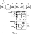
- Fig. 2 a schematic block diagram of the components of the lighting system 10 as well as the main circuit components of the light module and the control module are shown. However, it is to be noted that these block diagrams only show the main circuit parts and not every circuit necessary for achieving the described functions. A skilled person knows how to design the circuitry as to achieve the mentioned functions.
- the lighting system 10 as shown in Fig. 2 comprises at least three electrodes 16 connecting a control module 30 and several light modules 20.1 to 20.n.
- the supply voltage electrodes 16.1, 16.2 are electrically coupled with a power supply unit 40 which may be part of the lighting system 10 or which may be an external unit.
- the power supply unit 40 may be for example an AC/DC converter with an output voltage of 12 V. However, other voltages may also be possible depending on the application.
- the light module 20 comprises three electrode connector elements 26, two of which are electrically coupled with a power supply converter/controller circuit 44.
- This circuit 44 powers a light element 42, which may be provided as an organic light emitting diode (OLED) 43.
- OLED organic light emitting diode
- the light module 20 comprises a memory 46 for storing at least one parameter value transmitted by the control module 30.
- a further memory 47 may be provided for storing address data. As will be described below, this memory opens the possibility to address each individual light module via the control module.
- the memory 47 may be provided in form of an electronic memory, like EPROM, EEPROM, etc., or in form of an mechanical memory, like a DIP- switch, etc.
- the control module 30 comprises a controller circuit 32 which is electrically coupled with the electrode connector elements 36. Further, the control module 30 has a controller element 34 which is for example a rotary switch 35.
- the controller circuit 32 is powered via the power supply electrodes 16.1, 16.2 and generates control signals carrying a parameter which represents the brightness or color value given by the user by operating the rotary switch 35.
- This control signal is transmitted via the third electrode 16.3 and is received by the controller circuit 44 of the light modules 20. Further, the transmitted parameter value is stored in the memory 46. Beside the brightness or color parameter, the control module 30 may also transmit a signal representing an instruction for the light modules 20 to switch on or off.
- the light modules 20 as well as the control module 30 can make a translatory movement along the length of the substrate 12, as indicated by the arrows shown in Fig. 1 .
- the light modules as well as the control module 30 are almost freely placeable with the advantage that the control module 30 may be placed at a position allowing a convenient operation of the operating element 34 by the user.
- the light modules may comprise an address memory 47 allowing to transmit control signals to individual light modules.
- Each light module 20 has its own address stored in the address memory 47 - either set automatically or manually.
- the address is unique to each module 20 and allows the independent control of the individual light modules independently of each other.
- the address is preset by the manufacturer and can be modified by the user of the light system.
- the addresses may also be used to build groups of light modules which can be controlled independently by the controller.
- a group comprises one or more light modules 20.
- a communication protocol for the control data ensures the communication between the light modules 20 and the control module 30.
- Such kind of communication protocol can be a standard one, e.g. DALI; DMX or a proprietary one.
- control module 30 has an interface to an external host computer.
- the host computer might be used for easy set up of the lighting system.
- a further example of a lighting system 10' is schematically shown.
- the base module 11 only comprises two elongated parallel electrodes 16.1 and 16.2.
- Both electrodes 16 are not only provided for supplying power but are also used to transmit control signals generated by the control module 30 (which is not shown in Fig. 3 ). Since only two electrodes are used, it is necessary to transmit the control signal in a manner allowing to discriminate this signal at the light modules.
- several methods are known, for example power line protocols using modulated signals for transmitting information.
- control module to the light modules of the lighting system 10
- wireless RF or infrared communication can be used.
- communication for transmitting control signals can be done analog or digital.
- the light module (as well as the control module 30) comprises only two electrode connector elements 26.1 and 26.2.
- a further embodiment of a lighting system is schematically shown and indicated with reference numeral 10".
- the only difference to the aforementioned system is the design of the electrodes 16.
- the elongated electrodes 16 of the afore-mentioned embodiments are separated in a plurality of short electrode sections which are evenly spaced along the length of the substrate 12.
- all electrode sections of electrode 16.1 and 16.2, respectively are electrically connected via a connection line 16', which, however, lies in a different layer of the substrate 12.
- the electrode connector elements of the light module are provided as elongated connector lines 26.1, extending along the entire length of the modules 20, 30.
- the distance between two adjacent electrode sections 16.1, 16.2 is selected such that an electric contact with the electrode connector elements 26 of the modules 20, 30 is ensured irrespective of the position in the longitudinal direction of the substrate.
- a further embodiment of a lighting system is schematically shown.
- the substrate 12 carries a plurality of electrode pairs 51, each electrode pair 51 comprising two circular or ring-shaped electrode lines arranged concentrically.
- the outer circular electrode line is referenced with numeral 50 and the inner circular electrode line is referenced with numeral 52.
- each electrode line 50, 52 is connected with electrode 16.1 and electrode 16.2, respectively. Since both electrodes 16 extending in a different layer, interconnection points 54 are provided connecting the electrode lines 50, 52 with the respective electrode 16.1, 16.2.
- the electrode pairs 51 allow a rotatory movement of the light module 20 on the substrate 12. This is illustrated by the arrow on the front side of the light module 20.
- two electrode connector elements 26.1, 26.2 are provided, their distance to each other being the same as the distance between the circular electrode lines of an electrode pair.
- the electrode connector elements 26 are always in contact with the respective circular electrode lines 50, 52 irrespective of the angular position of the light module 20.
- Fig. 6 it is schematically shown that two or more substrates 12 may be cascaded by interconnecting their electrodes 16 via connection lines 48. This cascaded arrangement of the substrates 12 allows a matrix arrangement of light modules 20.
- a further embodiment of a lighting system is shown. It is a scalable lighting system with rotatory proof placement of light and control modules 20, 30.
- the left part shows the base module 11 comprising a substrate 12 carrying five electrodes 16.1, 16.2 and 16.3.
- the middle electrode 16.1 is externally connected to the ground potential (GND). Its both adjacent electrodes 16.2 are internally connected to each other and externally supplied by a positive supply voltage.
- the two remaining outer electrodes 16.3 are data line electrodes.
- the control module 30 comprises six pin-shaped electrode connector elements 36. Depending on the displacement angle of the control module 30 on the substrate 12, three of these electrode connector elements 36 are connected to the electrodes 16 of the base module if placed on it. Element 1 will be connected to GND and element 2 will be connected to the positive supply voltage.
- the control module generates a reference signal or control signal, which is transmitted to the outer two electrodes of the base module via element 3 of the control module.
- the signal can be adjusted by rotating the rotary switch 35 enabling dimming of the light modules 20.
- the electrode connector elements 26 of the other six light modules shown in Fig. 7 will be connected to ground, to the supply voltage and to the reference signal, respectively.
- the potentials applied to the three electrodes 16.1 to 16.3 are sent to the controller of the light modules 20 which control the current through the light element, for example an OLED.
- the substrate 12 carries several positioning elements 58 which may be provided as holes or recesses 59.
- the positioning elements are arranged at the outer longitudinal areas of the substrate in a predetermined pattern depending on the design of the used light and control modules.
- the positioning elements serve to position the light or control module on the substrate 12.
- each light and control module 20, 30 is provided with a counterpart positioning element, for example in form of pins 61 engaging with the recesses 59.
- the substrate 12 comprises a plurality of electrodes 16 or electrode sections 16 (for example in form of electrode points or pins) which are arranged in three lines and which are connected to respective electrodes 16' lying in a different layer beneath the electrode sections 16.
- the electrode sections 16 in the middle are supplied with ground and the other ones with the supply voltage.
- This specific pattern of electrode connector elements of the control and light modules 20, 30 allows to rotate the modules 20, 30 in 90° steps as shown in the lower part of Fig. 8 . Further, positioning elements 59 and 61 are provided to align each module 20, 30 in the longitudinal direction of the substrate 12.
- each light module 20 must comprise a polarity switch since the polarity is dependent on the rotary position of the light module.
- the light and control modules 20, 30 are provided with holding members used to hold them in a fixed position on the substrate 12.
- One solution for a holding member 28 is to provide pivotable clamps 64 on the back side of a light or control module 20, 30.
- the clamps 64 engage the back side of the substrate 12 achieving the necessary fixation.
- a further shown possibility is to use known screw connections 66.
- the substrate comprises magnetic areas 69 which may extend along the entire length of the substrate.
- Each light and control module 20, 30 comprises at least two magnets 68 arranged to cooperate with the magnetic areas 69 of the substrate.
- the light modules as well as the control module may be freely placeable and removable on and from the base module of the lighting system which offers increased design flexibility and improves handling and operating of the lighting system particularly by the possibility to freely place the modules.
Landscapes
- Engineering & Computer Science (AREA)
- General Engineering & Computer Science (AREA)
- Circuit Arrangement For Electric Light Sources In General (AREA)
- Non-Portable Lighting Devices Or Systems Thereof (AREA)
- Details Of Connecting Devices For Male And Female Coupling (AREA)
Claims (15)
- Steuermodul (30) für ein Beleuchtungssystem (10), wobei das Beleuchtungssystem (10) ein Basismodul (11) mit parallelen Elektroden (16) und mindestens ein mit den Elektroden (16) gekoppeltes Lichtmodul (20) zur Aufnahme von Energie umfasst, wobei das Steuermodul (30) umfasst:eine Steuerschaltung (32), die so eingerichtet ist, dass sie mindestens einen Parameter des mindestens einen Lichtmoduls (20) steuert, sowieein Halteelement (28), das so eingerichtet ist, dass es das Steuermodul (30) im Eingriff mit den Elektroden (16) des Beleuchtungssystems (10) lösbar hält, wobei das Steuermodul (30) so eingerichtet ist, dass es Energie für seinen Betrieb über die Elektroden (16) empfängt.
- Steuermodul (30) nach Anspruch 1, wobei der mindestens eine Parameter eine Helligkeit und/oder eine Farbe umfasst.
- Steuermodul (30) nach Anspruch 1, wobei das Halteelement (28) mindestens einen Magneten (68) umfasst, der so eingerichtet ist, dass er das Steuermodul (30) an dem Basismodul (11) fixiert.
- Steuermodul (30) nach Anspruch 1, wobei das Halteelement (28) mindestens eine Halteklammer (64) oder mindestens eine Schraubverbindung (66) umfasst.
- Steuermodul (30) nach Anspruch 1, wobei das Steuermodul (30) parallel zu den Elektroden (16) frei bewegbar ist und durch Betätigen des Halteelements (28) frei bewegbar ist.
- Steuermodul (30) nach Anspruch 1, wobei das Steuermodul (30) ein Positionierelement (58, 61) umfasst, das so eingerichtet ist, dass es mit einem an dem Basismodul (11) vorgesehenen Gegenelement (58, 59) in Eingriff kommt.
- Steuermodul (30) nach Anspruch 1, wobei die Elektroden (16) zwei Energie liefernde Elektroden (16.1, 16.2) umfassen, wobei das Steuermodul (30) so eingerichtet ist, dass es ein Steuersignal zur Steuerung des mindestens einen Parameters des mindestens einen Lichtmoduls (20) über die beiden Energie liefernden Elektroden (16.1, 16.2) oder über eine Datenelektrode (16.3) oder über eine drahtlose Funkfrequenz- oder Infrarot-Kommunikation überträgt.
- Steuermodul (30) nach Anspruch 1, wobei das Steuermodul (30) ein Steuerelement (34, 35) zur manuellen Einstellung des mindestens einen Parameters umfasst.
- Steuermodul (30) nach Anspruch 1, wobei das Steuermodul (30) eine Schnittstelle zu einem externen Host-Computer umfasst.
- Lichtmodul (20) für ein Beleuchtungssystem (10), wobei das Beleuchtungssystem (10) ein Basismodul (11) mit parallelen Elektroden (16) umfasst und das Lichtmodul (20) mit den Elektroden (16) zur Aufnahme von Energie gekoppelt ist, wobei das Lichtmodul (20) umfasst:mindestens zwei Elektrodenanschlusselemente (26), die zum Anschluss an die Elektroden (16) des Basismoduls (11) eingerichtet sind,ein Halteelement (28), das so eingerichtet ist, dass es das Lichtmodul (20) an dem Basismodul (11) lösbar hält, sowieeine Steuerschaltung (44) zur Steuerung von mindestens einem Parameter des Lichtmoduls (20) in Abhängigkeit eines von einem Steuermodul (30) nach Anspruch 7 empfangenen Steuersignals.
- Lichtmodul (20) nach Anspruch 10, wobei das Lichtmodul (20) ein Speicherelement (46) zur Speicherung eines Wertes des mindestens einen Parameters umfasst und das Lichtmodul (20) einen Adressenspeicher (47) zur Speicherung einer Adresse umfasst.
- Lichtmodul (20) nach Anspruch 10, wobei das Lichtmodul (20) ein Lichtelement (42) umfasst, das eine organische, Licht emittierende Diode (43) oder eine andere Licht emittierende Diode oder eine Halogenlampe umfasst.
- Beleuchtungssystem (10), umfassend:ein Basismodul (11) mit einem Substrat (12) und parallelen Elektroden (16) auf dem Substrat (12), sowiemindestens ein Modul (30, 20) nach Anspruch 1 oder 10.
- Beleuchtungssystem (10) nach Anspruch 13, wobei das Substrat (12) eine Leiterplatte (13) ist und die Elektroden (16) Leiterplattenleiter (17) sind.
- Beleuchtungssystem (10) nach Anspruch 13, wobei das Substrat (12) Bereiche (69) umfasst, die ein magnetisches Material tragen, das mit Magneten (68) eines Halteelements (28) des mindestens einen Moduls (30, 20) interagiert.
Priority Applications (1)
| Application Number | Priority Date | Filing Date | Title |
|---|---|---|---|
| EP08702590.4A EP2122244B1 (de) | 2007-02-12 | 2008-02-07 | Steuermodul für ein beleuchtungssystem, beleuchtungssystem und lichtmodul für ein beleuchtungssystem |
Applications Claiming Priority (3)
| Application Number | Priority Date | Filing Date | Title |
|---|---|---|---|
| EP07102169 | 2007-02-12 | ||
| PCT/IB2008/050438 WO2008099305A1 (en) | 2007-02-12 | 2008-02-07 | Control module for a lighting system, lighting system and light module for a lighting system |
| EP08702590.4A EP2122244B1 (de) | 2007-02-12 | 2008-02-07 | Steuermodul für ein beleuchtungssystem, beleuchtungssystem und lichtmodul für ein beleuchtungssystem |
Publications (2)
| Publication Number | Publication Date |
|---|---|
| EP2122244A1 EP2122244A1 (de) | 2009-11-25 |
| EP2122244B1 true EP2122244B1 (de) | 2016-05-11 |
Family
ID=39345189
Family Applications (1)
| Application Number | Title | Priority Date | Filing Date |
|---|---|---|---|
| EP08702590.4A Active EP2122244B1 (de) | 2007-02-12 | 2008-02-07 | Steuermodul für ein beleuchtungssystem, beleuchtungssystem und lichtmodul für ein beleuchtungssystem |
Country Status (6)
| Country | Link |
|---|---|
| US (1) | US8371728B2 (de) |
| EP (1) | EP2122244B1 (de) |
| JP (1) | JP5450098B2 (de) |
| CN (2) | CN101657679B (de) |
| RU (1) | RU2462659C2 (de) |
| WO (1) | WO2008099305A1 (de) |
Families Citing this family (46)
| Publication number | Priority date | Publication date | Assignee | Title |
|---|---|---|---|---|
| EP2122243B1 (de) | 2007-02-12 | 2016-04-20 | Philips Intellectual Property & Standards GmbH | Modulares elektrisches system |
| US8378591B2 (en) | 2007-11-30 | 2013-02-19 | Koninklijke Philips Electronics N.V. | Light output device |
| DE102008055798A1 (de) * | 2008-11-04 | 2010-05-06 | Werma Holding Gmbh + Co. Kg | Warnleuchte mit einer Sockeleinheit und wenigstens einer Leuchteinheit |
| JP2010165643A (ja) * | 2009-01-19 | 2010-07-29 | Kandenko Co Ltd | Led照明装置 |
| US8651711B2 (en) | 2009-02-02 | 2014-02-18 | Apex Technologies, Inc. | Modular lighting system and method employing loosely constrained magnetic structures |
| CN104115335A (zh) * | 2009-02-02 | 2014-10-22 | 艾派克斯技术股份有限公司 | 挠性磁性互连 |
| US8678612B2 (en) * | 2009-04-14 | 2014-03-25 | Phoseon Technology, Inc. | Modular light source |
| DE202010005878U1 (de) * | 2009-04-23 | 2011-04-21 | Müessli, Daniel | Beleuchtungssystem |
| US9847636B2 (en) * | 2012-10-03 | 2017-12-19 | Ideal Industries, Inc. | Low voltage buss system |
| US8427845B2 (en) | 2009-05-21 | 2013-04-23 | General Electric Company | Electrical connectors for optoelectronic device packaging |
| US8450926B2 (en) | 2009-05-21 | 2013-05-28 | General Electric Company | OLED lighting devices including electrodes with magnetic material |
| DE102009044058A1 (de) * | 2009-09-18 | 2011-03-31 | Müller, Dietmar | Dimmbare Lichterkette und Schalter hierfür |
| US9243759B2 (en) * | 2009-10-08 | 2016-01-26 | I/O Controls Corporation | LED-based lighting system for retrofitting fluorescent lighting fixtures in a transit vehicle |
| US8764220B2 (en) | 2010-04-28 | 2014-07-01 | Cooper Technologies Company | Linear LED light module |
| US8308320B2 (en) | 2009-11-12 | 2012-11-13 | Cooper Technologies Company | Light emitting diode modules with male/female features for end-to-end coupling |
| DE102009055847A1 (de) * | 2009-11-26 | 2011-06-01 | Ledon Lighting Jennersdorf Gmbh | Veränderbare Leuchtvorrichtung |
| ES2720356T3 (es) * | 2010-01-05 | 2019-07-19 | Signify Holding Bv | Motor de luz extraíble |
| JP5864440B2 (ja) * | 2010-01-29 | 2016-02-17 | ネーデルランゼ オルハニサティー フォール トゥーヘパスト−ナトゥールウェテンスハッペァイク オンデルゾーク テーエンオーNederlandse Organisatie Voor Toegepast−Natuurwetenschappelijk Onderzoek Tno | 集合体及び集合体を提供する方法 |
| DE102010014613A1 (de) * | 2010-04-09 | 2011-10-13 | Ledon Oled Lighting Gmbh & Co.Kg | Flächige Leuchtkörper, Anordnung von flächigen Leuchtkörpern und Verfahren zum Herstellen flächiger Leuchtkörper |
| US8616720B2 (en) | 2010-04-27 | 2013-12-31 | Cooper Technologies Company | Linkable linear light emitting diode system |
| FR2962878B1 (fr) * | 2010-07-16 | 2013-02-15 | Isabelle Mames | Dispositif pour la modularite et la regulation d'eclairages electroliminescents d'interieur ausage des particuliers et des professionnels |
| WO2012030536A2 (en) * | 2010-09-01 | 2012-03-08 | Apex Technologies, Inc. | Modular lighting system and method employing loosely constrained magnetic structures |
| CN201909192U (zh) * | 2010-09-26 | 2011-07-27 | 邓建伟 | 一种改进的led模组 |
| JP5698379B2 (ja) | 2010-12-15 | 2015-04-08 | モレックス インコーポレイテドMolex Incorporated | エネルギー消費デバイスおよびアセンブリ |
| ES2401191B1 (es) * | 2011-03-29 | 2013-11-26 | Jaime LLADÓ SENDRA | Sistema de sujeción magnética y conexión eléctrica simultánea para accionar luminarias con leds y aparatos eléctricos o electrónicos. |
| JP5828079B2 (ja) * | 2011-08-30 | 2015-12-02 | パナソニックIpマネジメント株式会社 | 照明装置及び照明システム |
| DK177534B1 (en) * | 2012-03-21 | 2013-09-08 | Martin Professional As | Flexible led pixel string with two shielding ground lines |
| DE202012101765U1 (de) * | 2012-05-14 | 2013-08-19 | Zumtobel Lighting Gmbh | Tragschiene zur Halterung und Stromversorgung mehrerer Leuchtmodule, sowie Lichtbandsystem mit einer solchen Tragschiene |
| BR112015004081A2 (pt) * | 2012-08-31 | 2017-07-04 | Koninklijke Philips Nv | sistema de distribuição de alimentação cc; sistema de determinação de posição sendo adaptado para ser utilizado no sistema de distribuição de alimentação cc; método de determinação de posição para determinar uma posição de um dispositivo elétrico ao longo de uma pista dentro de um sistema de distribuição de alimentação cc; e programa de computador para determinar uma posição de um dispositivo elétrico ao longo de uma pista dentro de um sistema de distribuição de alimentação cc |
| JP5945725B2 (ja) * | 2012-09-13 | 2016-07-05 | パナソニックIpマネジメント株式会社 | 照明装置およびそれを用いた照明装置ユニット |
| KR101439010B1 (ko) | 2013-03-13 | 2014-09-11 | 엘지이노텍 주식회사 | 통신 모듈을 포함하는 조명 장치 |
| GB2516853B (en) * | 2013-08-01 | 2016-09-14 | Clark-Ward Gary | A shelf power distribution apparatus |
| RU2672576C2 (ru) * | 2013-10-28 | 2018-11-16 | Филипс Лайтинг Холдинг Б.В. | Управление трековыми системами освещения, работающими на постоянном токе |
| CN104913237A (zh) * | 2014-03-16 | 2015-09-16 | 相阳 | 电灯具 |
| CN104333932B (zh) * | 2014-03-26 | 2017-01-18 | 南京第壹有机光电有限公司 | 一种可调整有机电致发光照明灯具 |
| EP2933551B1 (de) * | 2014-04-15 | 2017-06-14 | OSRAM GmbH | Beleuchtungsvorrichtung und ein entsprechendes Verfahren |
| KR101562795B1 (ko) * | 2014-04-29 | 2015-10-23 | 주식회사 필룩스 | 벽체 구조물 및 이를 이용한 조명 시스템 |
| RU2646591C2 (ru) * | 2015-09-29 | 2018-03-06 | Алексей Викторович Шторм | Устройство подведения электрического тока к группе светодиодных модулей |
| CN105938388A (zh) * | 2015-09-30 | 2016-09-14 | 杭州迪普科技有限公司 | 电源设备及具有其的通信设备 |
| CA2951310A1 (en) * | 2015-12-31 | 2017-06-30 | Ideal Industries, Inc. | Low voltage buss system |
| US9958148B2 (en) * | 2016-02-04 | 2018-05-01 | Ma Lighting Technology Gmbh | Lighting control console having a rotary control and method for operating a lighting control console having a rotary control |
| US11092293B2 (en) * | 2016-04-11 | 2021-08-17 | Artemide S.P.A. | Modular lighting system |
| TWI613395B (zh) * | 2016-11-10 | 2018-02-01 | 財團法人工業技術研究院 | 軌道式oled燈具組合 |
| US10955277B2 (en) | 2018-03-01 | 2021-03-23 | Tara Oilfield Services Ltd | Tank fill control apparatus and method |
| RU200303U1 (ru) * | 2019-11-26 | 2020-10-16 | Анастасия Юрьевна Мордовченко | Устройство для крепления светодиодных светильников |
| CN211625115U (zh) * | 2020-03-09 | 2020-10-02 | 上犹县嘉亿灯饰制品有限公司 | 点控铜线灯和灯具 |
Family Cites Families (24)
| Publication number | Priority date | Publication date | Assignee | Title |
|---|---|---|---|---|
| DE1803197U (de) * | 1957-02-14 | 1959-12-31 | Siemens Ag | Anschlusselemente. |
| JPS6041702A (ja) * | 1983-08-17 | 1985-03-05 | 三洋電機株式会社 | 点滅制御装置付照明器具 |
| US4688154A (en) * | 1983-10-19 | 1987-08-18 | Nilssen Ole K | Track lighting system with plug-in adapters |
| DE3447332A1 (de) * | 1984-12-24 | 1986-07-03 | Volker H. P. Dipl.-Ing. 8000 München Apel | Verbindung zwischen zwei mechanisch und elektrisch loesbar miteinander verbundenen teilen insbesondere eines beleuchtungssystems |
| DE3609660A1 (de) * | 1986-03-21 | 1987-10-01 | Bernhard Bartel | Elektrische einrichtung mit mindestens einer auf einer flaeche loesbar angeordneten elektrischen verbrauchereinheit |
| US7598686B2 (en) * | 1997-12-17 | 2009-10-06 | Philips Solid-State Lighting Solutions, Inc. | Organic light emitting diode methods and apparatus |
| DE19820104A1 (de) * | 1998-05-06 | 1999-11-11 | Knapp Michael G | Magnetisches Niedervolt-Stromzuführungssystem |
| DE29905034U1 (de) | 1999-03-19 | 1999-06-02 | Conradi, Georg, Montzen | Beleuchtungssystem |
| DE19942729A1 (de) * | 1999-09-08 | 2001-03-15 | Hella Kg Hueck & Co | Steuereinrichtung für eine Lichteinheit von Fahrzeugen |
| TWI273722B (en) | 2000-01-27 | 2007-02-11 | Gen Electric | Organic light emitting device and method for mounting |
| US6608283B2 (en) | 2000-02-08 | 2003-08-19 | Emagin Corporation | Apparatus and method for solder-sealing an active matrix organic light emitting diode |
| JP2002222611A (ja) * | 2001-01-25 | 2002-08-09 | Asahi Matsushita Electric Works Ltd | 配線ダクト |
| FR2836985A1 (fr) * | 2002-03-07 | 2003-09-12 | Bastien Christian Benoit Carre | Systeme d'eclairage a sources mobiles |
| DE10212232A1 (de) * | 2002-03-19 | 2003-10-09 | Semperlux Ag | Stromschiene mit Datenleitung |
| JP2004118015A (ja) | 2002-09-27 | 2004-04-15 | Sanyo Electric Co Ltd | 表示装置 |
| JP2004214036A (ja) * | 2002-12-26 | 2004-07-29 | Hakko Automation Kk | 遠隔制御可能な可変色発光体 |
| DE20307450U1 (de) * | 2003-05-13 | 2003-09-18 | Egoform GmbH, 26670 Uplengen | Lichtschiebeelement |
| JP2005063803A (ja) * | 2003-08-12 | 2005-03-10 | Matsushita Electric Works Ltd | 照明システム |
| RU45885U1 (ru) * | 2004-02-20 | 2005-05-27 | Открытое Акционерное Общество "Пеленг" | Устройство для управления осветительной системой |
| ITMI20040756A1 (it) | 2004-04-16 | 2004-07-16 | Vlm Spa | Sistema di illuminazione modulare comprendente moduli di illuminazione a led ad alta potenza |
| JP2005346958A (ja) * | 2004-05-31 | 2005-12-15 | Odelic Co Ltd | フィードインボックス型のリモコン受信装置 |
| US20060044215A1 (en) | 2004-08-24 | 2006-03-02 | Brody Thomas P | Scalable tiled display assembly for forming a large-area flat-panel display by using modular display tiles |
| EP1733653A3 (de) | 2005-06-13 | 2007-06-20 | SARNO S.p.A. | Leuchte für Schaukästen und/oder für Ausstellungsbereiche |
| EP1876389A1 (de) * | 2006-07-05 | 2008-01-09 | LiteCorp Europe B.V. | Beleuchtungssystem für Anzeigegerät |
-
2008
- 2008-02-07 WO PCT/IB2008/050438 patent/WO2008099305A1/en not_active Ceased
- 2008-02-07 CN CN2008800047072A patent/CN101657679B/zh active Active
- 2008-02-07 EP EP08702590.4A patent/EP2122244B1/de active Active
- 2008-02-07 US US12/525,850 patent/US8371728B2/en active Active
- 2008-02-07 JP JP2009548783A patent/JP5450098B2/ja active Active
- 2008-02-07 RU RU2009134181/28A patent/RU2462659C2/ru active
- 2008-02-07 CN CN2008800047068A patent/CN101636616B/zh active Active
Also Published As
| Publication number | Publication date |
|---|---|
| EP2122244A1 (de) | 2009-11-25 |
| US20100124067A1 (en) | 2010-05-20 |
| US8371728B2 (en) | 2013-02-12 |
| RU2462659C2 (ru) | 2012-09-27 |
| CN101657679B (zh) | 2013-10-30 |
| JP2010518570A (ja) | 2010-05-27 |
| CN101636616A (zh) | 2010-01-27 |
| CN101657679A (zh) | 2010-02-24 |
| CN101636616B (zh) | 2013-08-28 |
| RU2009134181A (ru) | 2011-03-20 |
| JP5450098B2 (ja) | 2014-03-26 |
| WO2008099305A1 (en) | 2008-08-21 |
Similar Documents
| Publication | Publication Date | Title |
|---|---|---|
| EP2122244B1 (de) | Steuermodul für ein beleuchtungssystem, beleuchtungssystem und lichtmodul für ein beleuchtungssystem | |
| EP2122243B1 (de) | Modulares elektrisches system | |
| AU2017281321B2 (en) | Driver system for a light emitting device | |
| US11580828B2 (en) | Modular indicator | |
| CN101690395A (zh) | 无线控制发光组件 | |
| KR102472603B1 (ko) | 가요성 led 디스플레이 모듈을 구비한 장치 및 이를 이용하는 방법 | |
| US20100259200A1 (en) | Led lighting device | |
| US20090322251A1 (en) | Large area lighting | |
| EP3712487B1 (de) | Kombinierte lampe und beleuchtungssystem | |
| JP5695088B2 (ja) | 複数の発光タイルを有する照明デバイス | |
| US20120242234A1 (en) | Low Voltage Coupling Design | |
| US20100176730A1 (en) | Illumination Apparatus | |
| US9374859B2 (en) | Lighting interconnection and lighting control module | |
| KR20140100875A (ko) | 발광모듈, 직관형 램프 및 조명 장치 | |
| KR101921817B1 (ko) | Led 조립 블록 및 이를 이용한 표시장치 | |
| KR20140132491A (ko) | 통신모듈 및 이를 포함하는 조명장치 | |
| CN207762689U (zh) | 一种组合灯具及照明系统 | |
| US8492991B2 (en) | Lighting fixture system for illumination using cold cathode fluorescent lamps | |
| WO2015011693A2 (en) | Modular light fixture | |
| CN112601910B (zh) | 模块化指示器 | |
| BG4440U1 (bg) | Електронно устройство за управление на лазерни и светодиодни светлинни ефекти | |
| KR20140124529A (ko) | 조명장치 | |
| TWM413940U (en) | Light emitting diode display light box | |
| CN109195277A (zh) | 一种多功能照明显示设备及其控制方法 |
Legal Events
| Date | Code | Title | Description |
|---|---|---|---|
| PUAI | Public reference made under article 153(3) epc to a published international application that has entered the european phase |
Free format text: ORIGINAL CODE: 0009012 |
|
| 17P | Request for examination filed |
Effective date: 20090914 |
|
| AK | Designated contracting states |
Kind code of ref document: A1 Designated state(s): AT BE BG CH CY CZ DE DK EE ES FI FR GB GR HR HU IE IS IT LI LT LU LV MC MT NL NO PL PT RO SE SI SK TR |
|
| DAX | Request for extension of the european patent (deleted) | ||
| RAP1 | Party data changed (applicant data changed or rights of an application transferred) |
Owner name: KONINKLIJKE PHILIPS N.V. Owner name: PHILIPS INTELLECTUAL PROPERTY & STANDARDS GMBH |
|
| GRAP | Despatch of communication of intention to grant a patent |
Free format text: ORIGINAL CODE: EPIDOSNIGR1 |
|
| INTG | Intention to grant announced |
Effective date: 20151021 |
|
| GRAS | Grant fee paid |
Free format text: ORIGINAL CODE: EPIDOSNIGR3 |
|
| GRAA | (expected) grant |
Free format text: ORIGINAL CODE: 0009210 |
|
| AK | Designated contracting states |
Kind code of ref document: B1 Designated state(s): AT BE BG CH CY CZ DE DK EE ES FI FR GB GR HR HU IE IS IT LI LT LU LV MC MT NL NO PL PT RO SE SI SK TR |
|
| REG | Reference to a national code |
Ref country code: GB Ref legal event code: FG4D |
|
| REG | Reference to a national code |
Ref country code: CH Ref legal event code: EP |
|
| REG | Reference to a national code |
Ref country code: AT Ref legal event code: REF Ref document number: 798956 Country of ref document: AT Kind code of ref document: T Effective date: 20160515 |
|
| REG | Reference to a national code |
Ref country code: IE Ref legal event code: FG4D |
|
| REG | Reference to a national code |
Ref country code: DE Ref legal event code: R096 Ref document number: 602008044166 Country of ref document: DE |
|
| REG | Reference to a national code |
Ref country code: LT Ref legal event code: MG4D |
|
| REG | Reference to a national code |
Ref country code: NL Ref legal event code: MP Effective date: 20160511 |
|
| RAP2 | Party data changed (patent owner data changed or rights of a patent transferred) |
Owner name: PHILIPS LIGHTING HOLDING B.V. |
|
| PG25 | Lapsed in a contracting state [announced via postgrant information from national office to epo] |
Ref country code: NL Free format text: LAPSE BECAUSE OF FAILURE TO SUBMIT A TRANSLATION OF THE DESCRIPTION OR TO PAY THE FEE WITHIN THE PRESCRIBED TIME-LIMIT Effective date: 20160511 Ref country code: NO Free format text: LAPSE BECAUSE OF FAILURE TO SUBMIT A TRANSLATION OF THE DESCRIPTION OR TO PAY THE FEE WITHIN THE PRESCRIBED TIME-LIMIT Effective date: 20160811 Ref country code: FI Free format text: LAPSE BECAUSE OF FAILURE TO SUBMIT A TRANSLATION OF THE DESCRIPTION OR TO PAY THE FEE WITHIN THE PRESCRIBED TIME-LIMIT Effective date: 20160511 Ref country code: LT Free format text: LAPSE BECAUSE OF FAILURE TO SUBMIT A TRANSLATION OF THE DESCRIPTION OR TO PAY THE FEE WITHIN THE PRESCRIBED TIME-LIMIT Effective date: 20160511 |
|
| REG | Reference to a national code |
Ref country code: GB Ref legal event code: 732E Free format text: REGISTERED BETWEEN 20161006 AND 20161012 |
|
| REG | Reference to a national code |
Ref country code: AT Ref legal event code: MK05 Ref document number: 798956 Country of ref document: AT Kind code of ref document: T Effective date: 20160511 |
|
| PG25 | Lapsed in a contracting state [announced via postgrant information from national office to epo] |
Ref country code: LV Free format text: LAPSE BECAUSE OF FAILURE TO SUBMIT A TRANSLATION OF THE DESCRIPTION OR TO PAY THE FEE WITHIN THE PRESCRIBED TIME-LIMIT Effective date: 20160511 Ref country code: SE Free format text: LAPSE BECAUSE OF FAILURE TO SUBMIT A TRANSLATION OF THE DESCRIPTION OR TO PAY THE FEE WITHIN THE PRESCRIBED TIME-LIMIT Effective date: 20160511 Ref country code: ES Free format text: LAPSE BECAUSE OF FAILURE TO SUBMIT A TRANSLATION OF THE DESCRIPTION OR TO PAY THE FEE WITHIN THE PRESCRIBED TIME-LIMIT Effective date: 20160511 Ref country code: PT Free format text: LAPSE BECAUSE OF FAILURE TO SUBMIT A TRANSLATION OF THE DESCRIPTION OR TO PAY THE FEE WITHIN THE PRESCRIBED TIME-LIMIT Effective date: 20160912 Ref country code: GR Free format text: LAPSE BECAUSE OF FAILURE TO SUBMIT A TRANSLATION OF THE DESCRIPTION OR TO PAY THE FEE WITHIN THE PRESCRIBED TIME-LIMIT Effective date: 20160812 Ref country code: HR Free format text: LAPSE BECAUSE OF FAILURE TO SUBMIT A TRANSLATION OF THE DESCRIPTION OR TO PAY THE FEE WITHIN THE PRESCRIBED TIME-LIMIT Effective date: 20160511 |
|
| PG25 | Lapsed in a contracting state [announced via postgrant information from national office to epo] |
Ref country code: IT Free format text: LAPSE BECAUSE OF FAILURE TO SUBMIT A TRANSLATION OF THE DESCRIPTION OR TO PAY THE FEE WITHIN THE PRESCRIBED TIME-LIMIT Effective date: 20160511 |
|
| PG25 | Lapsed in a contracting state [announced via postgrant information from national office to epo] |
Ref country code: EE Free format text: LAPSE BECAUSE OF FAILURE TO SUBMIT A TRANSLATION OF THE DESCRIPTION OR TO PAY THE FEE WITHIN THE PRESCRIBED TIME-LIMIT Effective date: 20160511 Ref country code: RO Free format text: LAPSE BECAUSE OF FAILURE TO SUBMIT A TRANSLATION OF THE DESCRIPTION OR TO PAY THE FEE WITHIN THE PRESCRIBED TIME-LIMIT Effective date: 20160511 Ref country code: SK Free format text: LAPSE BECAUSE OF FAILURE TO SUBMIT A TRANSLATION OF THE DESCRIPTION OR TO PAY THE FEE WITHIN THE PRESCRIBED TIME-LIMIT Effective date: 20160511 Ref country code: CZ Free format text: LAPSE BECAUSE OF FAILURE TO SUBMIT A TRANSLATION OF THE DESCRIPTION OR TO PAY THE FEE WITHIN THE PRESCRIBED TIME-LIMIT Effective date: 20160511 Ref country code: DK Free format text: LAPSE BECAUSE OF FAILURE TO SUBMIT A TRANSLATION OF THE DESCRIPTION OR TO PAY THE FEE WITHIN THE PRESCRIBED TIME-LIMIT Effective date: 20160511 |
|
| REG | Reference to a national code |
Ref country code: DE Ref legal event code: R097 Ref document number: 602008044166 Country of ref document: DE |
|
| REG | Reference to a national code |
Ref country code: DE Ref legal event code: R081 Ref document number: 602008044166 Country of ref document: DE Owner name: SIGNIFY HOLDING B.V., NL Free format text: FORMER OWNER: PHILIPS INTELLECTUAL PROPERTY & STANDARDS GMBH, 20099 HAMBURG, DE Ref country code: DE Ref legal event code: R081 Ref document number: 602008044166 Country of ref document: DE Owner name: SIGNIFY HOLDING B.V., NL Free format text: FORMER OWNER: PHILIPS DEUTSCHLAND GMBH, 20099 HAMBURG, DE Ref country code: DE Ref legal event code: R081 Ref document number: 602008044166 Country of ref document: DE Owner name: SIGNIFY HOLDING B.V., NL Free format text: FORMER OWNER: PHILIPS GMBH, 20099 HAMBURG, DE Ref country code: DE Ref legal event code: R082 Ref document number: 602008044166 Country of ref document: DE Representative=s name: MEISSNER BOLTE PATENTANWAELTE RECHTSANWAELTE P, DE Ref country code: DE Ref legal event code: R081 Ref document number: 602008044166 Country of ref document: DE Owner name: PHILIPS LIGHTING HOLDING B.V., NL Free format text: FORMER OWNER: PHILIPS DEUTSCHLAND GMBH, 20099 HAMBURG, DE Ref country code: DE Ref legal event code: R081 Ref document number: 602008044166 Country of ref document: DE Owner name: PHILIPS LIGHTING HOLDING B.V., NL Free format text: FORMER OWNER: PHILIPS INTELLECTUAL PROPERTY & STANDARDS GMBH, 20099 HAMBURG, DE Ref country code: DE Ref legal event code: R081 Ref document number: 602008044166 Country of ref document: DE Owner name: PHILIPS LIGHTING HOLDING B.V., NL Free format text: FORMER OWNER: PHILIPS GMBH, 20099 HAMBURG, DE |
|
| REG | Reference to a national code |
Ref country code: FR Ref legal event code: PLFP Year of fee payment: 10 |
|
| PG25 | Lapsed in a contracting state [announced via postgrant information from national office to epo] |
Ref country code: PL Free format text: LAPSE BECAUSE OF FAILURE TO SUBMIT A TRANSLATION OF THE DESCRIPTION OR TO PAY THE FEE WITHIN THE PRESCRIBED TIME-LIMIT Effective date: 20160511 Ref country code: BE Free format text: LAPSE BECAUSE OF FAILURE TO SUBMIT A TRANSLATION OF THE DESCRIPTION OR TO PAY THE FEE WITHIN THE PRESCRIBED TIME-LIMIT Effective date: 20160511 Ref country code: AT Free format text: LAPSE BECAUSE OF FAILURE TO SUBMIT A TRANSLATION OF THE DESCRIPTION OR TO PAY THE FEE WITHIN THE PRESCRIBED TIME-LIMIT Effective date: 20160511 |
|
| PLBE | No opposition filed within time limit |
Free format text: ORIGINAL CODE: 0009261 |
|
| STAA | Information on the status of an ep patent application or granted ep patent |
Free format text: STATUS: NO OPPOSITION FILED WITHIN TIME LIMIT |
|
| 26N | No opposition filed |
Effective date: 20170214 |
|
| PG25 | Lapsed in a contracting state [announced via postgrant information from national office to epo] |
Ref country code: SI Free format text: LAPSE BECAUSE OF FAILURE TO SUBMIT A TRANSLATION OF THE DESCRIPTION OR TO PAY THE FEE WITHIN THE PRESCRIBED TIME-LIMIT Effective date: 20160511 |
|
| PG25 | Lapsed in a contracting state [announced via postgrant information from national office to epo] |
Ref country code: MC Free format text: LAPSE BECAUSE OF FAILURE TO SUBMIT A TRANSLATION OF THE DESCRIPTION OR TO PAY THE FEE WITHIN THE PRESCRIBED TIME-LIMIT Effective date: 20160511 |
|
| REG | Reference to a national code |
Ref country code: CH Ref legal event code: PL |
|
| PG25 | Lapsed in a contracting state [announced via postgrant information from national office to epo] |
Ref country code: LI Free format text: LAPSE BECAUSE OF NON-PAYMENT OF DUE FEES Effective date: 20170228 Ref country code: CH Free format text: LAPSE BECAUSE OF NON-PAYMENT OF DUE FEES Effective date: 20170228 |
|
| REG | Reference to a national code |
Ref country code: IE Ref legal event code: MM4A |
|
| PG25 | Lapsed in a contracting state [announced via postgrant information from national office to epo] |
Ref country code: LU Free format text: LAPSE BECAUSE OF NON-PAYMENT OF DUE FEES Effective date: 20170207 |
|
| REG | Reference to a national code |
Ref country code: FR Ref legal event code: PLFP Year of fee payment: 11 |
|
| PG25 | Lapsed in a contracting state [announced via postgrant information from national office to epo] |
Ref country code: IE Free format text: LAPSE BECAUSE OF NON-PAYMENT OF DUE FEES Effective date: 20170207 |
|
| PG25 | Lapsed in a contracting state [announced via postgrant information from national office to epo] |
Ref country code: MT Free format text: LAPSE BECAUSE OF NON-PAYMENT OF DUE FEES Effective date: 20170207 |
|
| PG25 | Lapsed in a contracting state [announced via postgrant information from national office to epo] |
Ref country code: HU Free format text: LAPSE BECAUSE OF FAILURE TO SUBMIT A TRANSLATION OF THE DESCRIPTION OR TO PAY THE FEE WITHIN THE PRESCRIBED TIME-LIMIT; INVALID AB INITIO Effective date: 20080207 |
|
| PG25 | Lapsed in a contracting state [announced via postgrant information from national office to epo] |
Ref country code: BG Free format text: LAPSE BECAUSE OF FAILURE TO SUBMIT A TRANSLATION OF THE DESCRIPTION OR TO PAY THE FEE WITHIN THE PRESCRIBED TIME-LIMIT Effective date: 20160511 |
|
| PG25 | Lapsed in a contracting state [announced via postgrant information from national office to epo] |
Ref country code: CY Free format text: LAPSE BECAUSE OF NON-PAYMENT OF DUE FEES Effective date: 20160511 |
|
| PG25 | Lapsed in a contracting state [announced via postgrant information from national office to epo] |
Ref country code: TR Free format text: LAPSE BECAUSE OF FAILURE TO SUBMIT A TRANSLATION OF THE DESCRIPTION OR TO PAY THE FEE WITHIN THE PRESCRIBED TIME-LIMIT Effective date: 20160511 |
|
| PG25 | Lapsed in a contracting state [announced via postgrant information from national office to epo] |
Ref country code: IS Free format text: LAPSE BECAUSE OF FAILURE TO SUBMIT A TRANSLATION OF THE DESCRIPTION OR TO PAY THE FEE WITHIN THE PRESCRIBED TIME-LIMIT Effective date: 20160911 |
|
| REG | Reference to a national code |
Ref country code: DE Ref legal event code: R082 Ref document number: 602008044166 Country of ref document: DE Representative=s name: MEISSNER BOLTE PATENTANWAELTE RECHTSANWAELTE P, DE Ref country code: DE Ref legal event code: R081 Ref document number: 602008044166 Country of ref document: DE Owner name: SIGNIFY HOLDING B.V., NL Free format text: FORMER OWNER: PHILIPS LIGHTING HOLDING B.V., EINDHOVEN, NL |
|
| P01 | Opt-out of the competence of the unified patent court (upc) registered |
Effective date: 20230421 |
|
| PGFP | Annual fee paid to national office [announced via postgrant information from national office to epo] |
Ref country code: DE Payment date: 20250428 Year of fee payment: 18 |
|
| PGFP | Annual fee paid to national office [announced via postgrant information from national office to epo] |
Ref country code: GB Payment date: 20260223 Year of fee payment: 19 |
|
| PGFP | Annual fee paid to national office [announced via postgrant information from national office to epo] |
Ref country code: FR Payment date: 20260224 Year of fee payment: 19 |