EP2123236B1 - Butée détachable pour fraise dentaire - Google Patents
Butée détachable pour fraise dentaire Download PDFInfo
- Publication number
- EP2123236B1 EP2123236B1 EP09006234A EP09006234A EP2123236B1 EP 2123236 B1 EP2123236 B1 EP 2123236B1 EP 09006234 A EP09006234 A EP 09006234A EP 09006234 A EP09006234 A EP 09006234A EP 2123236 B1 EP2123236 B1 EP 2123236B1
- Authority
- EP
- European Patent Office
- Prior art keywords
- main body
- stopper main
- expanding tool
- diameter
- diameter expanding
- Prior art date
- Legal status (The legal status is an assumption and is not a legal conclusion. Google has not performed a legal analysis and makes no representation as to the accuracy of the status listed.)
- Not-in-force
Links
- 238000003780 insertion Methods 0.000 claims abstract description 93
- 230000037431 insertion Effects 0.000 claims abstract description 93
- 230000002093 peripheral effect Effects 0.000 claims abstract description 72
- 239000007769 metal material Substances 0.000 claims abstract description 7
- 239000007943 implant Substances 0.000 claims description 39
- 230000007423 decrease Effects 0.000 claims description 4
- 229910001069 Ti alloy Inorganic materials 0.000 claims description 3
- 238000000034 method Methods 0.000 description 9
- 238000010079 rubber tapping Methods 0.000 description 6
- 230000002950 deficient Effects 0.000 description 5
- 230000005489 elastic deformation Effects 0.000 description 4
- 230000001105 regulatory effect Effects 0.000 description 4
- 239000004053 dental implant Substances 0.000 description 3
- 239000000463 material Substances 0.000 description 3
- 210000004195 gingiva Anatomy 0.000 description 2
- 229910052782 aluminium Inorganic materials 0.000 description 1
- XAGFODPZIPBFFR-UHFFFAOYSA-N aluminium Chemical compound [Al] XAGFODPZIPBFFR-UHFFFAOYSA-N 0.000 description 1
- 230000000087 stabilizing effect Effects 0.000 description 1
- 238000003325 tomography Methods 0.000 description 1
Images



Classifications
-
- B—PERFORMING OPERATIONS; TRANSPORTING
- B23—MACHINE TOOLS; METAL-WORKING NOT OTHERWISE PROVIDED FOR
- B23B—TURNING; BORING
- B23B49/00—Measuring or gauging equipment on boring machines for positioning or guiding the drill; Devices for indicating failure of drills during boring; Centering devices for holes to be bored
- B23B49/003—Stops attached to drilling tools, tool holders or drilling machines
- B23B49/005—Attached to the drill
-
- A—HUMAN NECESSITIES
- A61—MEDICAL OR VETERINARY SCIENCE; HYGIENE
- A61B—DIAGNOSIS; SURGERY; IDENTIFICATION
- A61B17/00—Surgical instruments, devices or methods
- A61B17/16—Instruments for performing osteoclasis; Drills or chisels for bones; Trepans
- A61B17/1662—Instruments for performing osteoclasis; Drills or chisels for bones; Trepans for particular parts of the body
- A61B17/1673—Instruments for performing osteoclasis; Drills or chisels for bones; Trepans for particular parts of the body for the jaw
-
- A—HUMAN NECESSITIES
- A61—MEDICAL OR VETERINARY SCIENCE; HYGIENE
- A61C—DENTISTRY; APPARATUS OR METHODS FOR ORAL OR DENTAL HYGIENE
- A61C8/00—Means to be fixed to the jaw-bone for consolidating natural teeth or for fixing dental prostheses thereon; Dental implants; Implanting tools
- A61C8/0089—Implanting tools or instruments
-
- A—HUMAN NECESSITIES
- A61—MEDICAL OR VETERINARY SCIENCE; HYGIENE
- A61B—DIAGNOSIS; SURGERY; IDENTIFICATION
- A61B90/00—Instruments, implements or accessories specially adapted for surgery or diagnosis and not covered by any of the groups A61B1/00 - A61B50/00, e.g. for luxation treatment or for protecting wound edges
- A61B90/03—Automatic limiting or abutting means, e.g. for safety
- A61B2090/033—Abutting means, stops, e.g. abutting on tissue or skin
- A61B2090/036—Abutting means, stops, e.g. abutting on tissue or skin abutting on tissue or skin
-
- A—HUMAN NECESSITIES
- A61—MEDICAL OR VETERINARY SCIENCE; HYGIENE
- A61C—DENTISTRY; APPARATUS OR METHODS FOR ORAL OR DENTAL HYGIENE
- A61C5/00—Filling or capping teeth
- A61C5/40—Implements for surgical treatment of the roots or nerves of the teeth; Nerve needles; Methods or instruments for medication of the roots
- A61C5/44—Means for controlling working depth, e.g. supports or boxes with depth-gauging means, stop positioners or files with adjustably-mounted handles
-
- Y—GENERAL TAGGING OF NEW TECHNOLOGICAL DEVELOPMENTS; GENERAL TAGGING OF CROSS-SECTIONAL TECHNOLOGIES SPANNING OVER SEVERAL SECTIONS OF THE IPC; TECHNICAL SUBJECTS COVERED BY FORMER USPC CROSS-REFERENCE ART COLLECTIONS [XRACs] AND DIGESTS
- Y10—TECHNICAL SUBJECTS COVERED BY FORMER USPC
- Y10T—TECHNICAL SUBJECTS COVERED BY FORMER US CLASSIFICATION
- Y10T24/00—Buckles, buttons, clasps, etc.
- Y10T24/44—Clasp, clip, support-clamp, or required component thereof
- Y10T24/44009—Gripping member adapted for tool actuation or release
-
- Y—GENERAL TAGGING OF NEW TECHNOLOGICAL DEVELOPMENTS; GENERAL TAGGING OF CROSS-SECTIONAL TECHNOLOGIES SPANNING OVER SEVERAL SECTIONS OF THE IPC; TECHNICAL SUBJECTS COVERED BY FORMER USPC CROSS-REFERENCE ART COLLECTIONS [XRACs] AND DIGESTS
- Y10—TECHNICAL SUBJECTS COVERED BY FORMER USPC
- Y10T—TECHNICAL SUBJECTS COVERED BY FORMER US CLASSIFICATION
- Y10T24/00—Buckles, buttons, clasps, etc.
- Y10T24/44—Clasp, clip, support-clamp, or required component thereof
- Y10T24/44966—Clasp, clip, support-clamp, or required component thereof having gripping member shifted by operator
- Y10T24/44974—Threaded cylindrical rod and mating cavity
-
- Y—GENERAL TAGGING OF NEW TECHNOLOGICAL DEVELOPMENTS; GENERAL TAGGING OF CROSS-SECTIONAL TECHNOLOGIES SPANNING OVER SEVERAL SECTIONS OF THE IPC; TECHNICAL SUBJECTS COVERED BY FORMER USPC CROSS-REFERENCE ART COLLECTIONS [XRACs] AND DIGESTS
- Y10—TECHNICAL SUBJECTS COVERED BY FORMER USPC
- Y10T—TECHNICAL SUBJECTS COVERED BY FORMER US CLASSIFICATION
- Y10T408/00—Cutting by use of rotating axially moving tool
- Y10T408/89—Tool or Tool with support
- Y10T408/892—Tool or Tool with support with work-engaging structure detachable from cutting edge
- Y10T408/8925—Depth-limiting member
Definitions
- the present invention relates to a detachable stopper for a dental drill for regulating a depth of a hole.
- the dental drill is for boring an implant fixture embedding hole in an implant treatment and has a blade part on the front end side of the spindle part.
- the spindle part has a diameter shrunk part formed as a mounting part for preventing slipping-off to a dental hand piece at a rear end thereof, or a cylindrical shape having an equal diameter without having the diameter shrunk part.
- the detachable stopper is externally fitted to and fixed at a position on a spindle part of a dental drill, from the front end side or rear end side of the dental drill so as to regulate the depth of the hole.
- a dental implant treatment technique for fixing a dental prosthesis at a dental prosthesis maintaining device is developed and carried out.
- an implant fixture as a maintaining and stabilizing device of the dental prosthesis is embedded into an implant fixture embedding hole formed in a jawbone at a defective tooth so as to act for a function of a tooth root of a natural tooth.
- a dental prosthesis maintaining device is made by connecting and fixing a fixing device of a dental prosthesis on the intra-oral side of the implant fixture and the dental prosthesis is fixed to the dental prosthesis maintaining device.
- a dental driving device such as a hand piece or the like, having a dental drill having a spindle part and a blade part formed at the front end side of the spindle part is used, and the hole is bored in the jawbone at the defective tooth by the blade part of the dental drill.
- the spindle part has a diameter shrunk part, which is formed as a mounting part for preventing slipping-off to a dental hand piece, at a rear end thereof, or has a cylindrical shape having an equal diameter without having the diameter shrunk part.
- the implant fixture embedding hole formed by the aforementioned operation does not have a proper depth, there occurs a problem that a dental prosthesis cannot be fixed to the implant fixture embedded in the implant fixture embedding hole or the implant fixture cannot be stably embedded in the implant fixture embedding hole. In addition to this, there may be a trouble that the jawbone is damaged in the worst case. Therefore, in such the implant treatment, it is the most important thing that the implant fixture embedding hole is formed at an exact position in the jawbone at the defective tooth with an exact depth.
- WO-A-03 071 972 discloses a method for arranging a dental implant by using a drill with a flange. That is, the method includes the step of producing a template by downloading a tomography of a jawbone of a patient to a computer, and by forming therein a hole having a specified embedding direction of a fixture on the basis of data in which the embedding direction of the fixture is previously determined and a complete state of a prosthesis device including the fixture is correctly simulated. The method also includes use of a dental drill with a flange which is for regulating a depth of an implant fixture embedding hole and integrally formed with a spindle part.
- the position and direction of the implant fixture embedding hole are specified with the template, and the depth of the implant fixture embedding hole is regulated by positioning of the flange of the dental drill with a flange.
- the dental drill with a flange has a structure in which the flange for regulating the depth of the implant fixture embedding hole is formed integrally with the spindle part, in case of the method by using the template and the dental drill with a flange, there is a fault that several kinds of dental drills with a flange, each of which has only a different position in an axial direction of the flange corresponding to a depth of the implant fixture embedding hole, must be prepared, even though each of these dental drills with a flange has a completely same shape of a blade part. Further, generally, plural kinds of dental drills having different shapes of blade parts respectively must be prepared. Thus, there is a fault that vast kinds of dental drills with a flange, each of which has only a different position in an axial direction of the flange, must be prepared for every plural kinds of the blade parts. Therefore, an economic burden is great.
- EP-A-0 515 274 describes a detachable stopper for a dental drill in the form of a resilient metallic ring with a radial slit. The slit allows an expansion of the ring when being mounted to the drill bit.
- the present invention is directed to provide a detachable stopper for a dental drill so as to solve the aforementioned faults.
- the detachable stopper is externally fitted to and fixed at a position on a spindle part of a dental drill, which is for boring an implant fixture embedding hole in an implant treatment, from the front end side or rear end side of the dental drill and regulates a depth of a hole.
- the dental drill has a blade part at the front end side of the spindle part and the spindle part has a diameter shrunk part, which is formed as a mounting part for preventing slipping-off to a dental hand piece, at a rear end thereof, or is in a cylindrical shape having an equal diameter without having the diameter shrunk part.
- the detachable stopper for a dental drill can maintain a state of being accurately fitted externally to the spindle part of the dental drill, and can be easily attached and detached.
- a detachable stopper for a dental drill includes a stopper main body being made of an elastically deformable metal material, having a cylindrical shape, having a slightly smaller inner diameter than an outer diameter of a spindle part of a dental drill in a stationary state, having a slit part formed along an axial overall length thereof from an outer peripheral face to an inner peripheral face so as to have an opening, and having an diameter expanding tool insertion part bored at an axial center part of the slit part.
- the detachable stopper for a dental drill also includes a diameter expanding tool having a shape which can be freely inserted into and removed from the diameter expanding tool insertion part of the stopper main body, and being inserted into the diameter expanding tool insertion part of the stopper main body so as to expand the inner diameter of the stopper main body to be larger than the outer diameter of the spindle part of the dental drill.
- a diameter expanding tool having a shape which can be freely inserted into and removed from the diameter expanding tool insertion part of the stopper main body, and being inserted into the diameter expanding tool insertion part of the stopper main body so as to expand the inner diameter of the stopper main body to be larger than the outer diameter of the spindle part of the dental drill.
- the inner diameter of the stopper main body becomes in a stationary state of being slightly smaller than the outer diameter of the spindle part of the dental drill, that is, in a state in which the stopper main body is externally fitted to and fixed to a position at the spindle part of the dental drill. Therefore, only by an easy operation of inserting/removing the diameter expanding tool into/from the diameter expanding tool insertion part of the stopper main body, the stopper main body can change to be in either the diameter expanding state or the stationary state. Thus, the stopper can maintain a state of being accurately fitted externally to the spindle part of the dental drill, and can be easily attached and detached.
- the dental drill without a flange can be used as a dental drill which can regulate the depth of the implant fixture embedding hole, like a conventional dental drill with a flange. Therefore, many conventionally used general dental drills without a flange do not become useless and an economical burden can be greatly reduced.
- the implant fixture embedding hole having a proper depth can be bored only by changing the axial position of the stopper and fixing it, when the stopper is externally fitted to the spindle part of the dental drill.
- the detachable stopper for a dental drill according to the present invention can be fixed at a freely changed axial position when the stopper main body is externally fitted to the spindle part of the dental drill.
- one dental drill can be freely applied continuously to depths of the implant fixture embedding hole.
- the diameter expanding tool insertion part of the stopper main body has a reduced portion, which is formed so as to have reduced cross section areas from an outer peripheral side toward an inner peripheral side, and to have similar cross section shapes from the outer peripheral side to the inner peripheral side, and in addition, the front end side of the diameter expanding tool is formed so as to have a slightly larger cross section than the cross section at the inner peripheral side of the reduced portion of the diameter expanding tool insertion part of the stopper main body.
- the diameter expanding tool insertion part of the stopper main body is formed to have an approximately same cross section from the outer peripheral side to the inner peripheral side, and in addition, the front end side of the diameter expanding tool is formed to have a cross section area smaller than the cross section area of the diameter expanding tool insertion part of the stopper main body.
- This cross section area of the expanding tool gradually decreases towards a front end from a portion having a larger cross section area than the cross section area of the diameter expanding tool insertion part of the stopper main body.
- the diameter expanding tool insertion part of the stopper main body may have the circular cross section and may have the female screw on an inner face at the outer peripheral side, and in addition, the diameter expanding tool may have the male screw to be screwed into the female screw of the diameter expanding tool insertion part of the stopper main body.
- the diameter expanding tool when the diameter expanding tool is screwed into the diameter expanding tool insertion part of the stopper main body, the inner diameter of the stopper main body can be easily expanded, so it is preferable.
- the stopper main body can change to be either in the diameter expanding state or in the stationary state. Thus, the force required for expanding the inner diameter of the stopper main body can be reduced, so it is preferable.
- the diameter expanding auxiliary portion may be recessed towards the inner peripheral side along an axial overall length is formed on the outer peripheral face side of a portion opposite to the slit part beyond a center axis of the stopper main body.
- the stopper main body can be stably put on a flat face, e.g., on a table, in a state that the diameter expanding tool insertion part is upwardly directed and the diameter expanding auxiliary portion contacts to the flat face, e.g. , to a table.
- the stopper main body is put on the flat face, e.g., on a table at a time of inserting/removing the diameter expanding tool into/from the diameter expanding tool insertion part of the stopper main body, the handling of the inserting and removing can be easily carried out, so it is preferable.
- the stopper main body When the stopper main body is made of a titanium alloy, the material has biocompatibility required in an implant treatment. In a case of boring the implant fixture embedding hole without using a template having a hole formed to have a specified embedding direction of a fixture, when the stopper main body directly contacts to a living body such as a gingiva, the influence given to a living body can be reduced, so it is preferable. In addition, since durability can be improved, it is preferable.
- a detachable stopper for a dental drill according to the present invention will be described in detail below with reference to drawings.
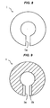
- a stopper main body 1 is made of an elastically deformable metal material, has a cylindrical shape, has a slightly smaller inner diameter than an outer diameter of a spindle part D3 of a dental drill D in a stationary state, has a slit part 1a formed along an axial overall length from an outer peripheral face to an inner peripheral face so as to have an opening, and has a diameter expanding tool insertion part 1b bored at an axial center part of the slit part 1a.
- the stopper main body 1 is externally fitted from the front end side or rear end side of the dental drill D and fixed at a position on the spindle part D3 of the dental drill D so as to regulate a depth of an implant fixture embedding hole.
- the stopper main body 1 has a cylindrical shape and has the slit part 1a which is formed along the axial overall length from the outer peripheral face to the inner peripheral face thereof so as to have an opening.
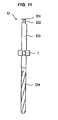
- the stopper main body 1 has the diameter expanding tool insertion part 1b bored at the axial center part of the slit part 1a. Further, when the stopper main body 1 is externally fitted to and fixed at a position on the spindle part D3 of the dental drill D as illustrated in Fig.
- the inner diameter of the stopper main body 1 is expanded to be larger than the outer diameter of the spindle D3 of the dental drill D so as to make a diameter expanding state in which the stopper main body 1 can be fitted from the front end side or rear end side of the dental drill D, by inserting a diameter expanding tool 2 described below into the diameter expanding tool insertion part 1b of the stopper main body 1 as illustrated in Figs. 6 and 10 , because the inner diameter of the stopper main body 1 is slightly smaller than the outer diameter of the spindle part D3 of the dental drill D in the stationary state as illustrated in Figs. 5 and 9 . In this state, the stopper main body 1 with the diameter expanding tool 2 inserted therein can be fitted from the front end side or rear end side of the dental drill D and moved to a proper position on the spindle D3 of the dental drill D.
- the stopper main body 1 with the diameter expanding tool 2 inserted therein is inserted from the front end side or rear end side of the dental drill D and moved to a proper position on the spindle D3 of the dental drill D, the inner diameter is returned to the stationary state, of being slightly smaller than the outer diameter of the spindle part D3 of the dental drill D, by elastic deformation force of the metal material, when the diameter expanding tool 2 is removed from the diameter expanding tool insertion part 1b of the stopper main body 1.
- the stopper main body 1 can keep a state of being accurately fitted externally to and fixed on the spindle part D3 of the dental drill D by the elastic deformation force.
- the diameter expanding tool 2 described below is inserted into the diameter expanding tool insertion part 1b of the stopper main body 1 as illustrated in Figs. 6 and 10 .
- the inner diameter of the stopper main body 1 is expanded to be larger than the outer diameter of the spindle part D3 of the dental drill D so as to make the diameter expanding state in which the stopper main body 1 can be inserted from the front end side or rear end side of the dental drill D.
- the stopper main body 1 with the diameter expanding tool 2 inserted therein can be pulled out from the front end side or rear end side of the dental drill D.
- the stopper main body 1 has the slit part 1a formed along the axial overall length from the outer peripheral face to the inner peripheral face. Owing to the slit part 1a having such the structure, the stopper main body 1 can change to be either in the stationary state in which the inner diameter of the stopper main body 1 is slightly smaller than the outer diameter of the spindle part D3 of the dental drill D as illustrated in Figs. 5 and 9 , or in the diameter expanding state in which the inner diameter of the stopper main body 1 is larger than the outer diameter of the spindle part D3 of the dental drill D, that is, the width of the slit part 1a is deformed to be larger than that in the stationary state, as illustrated in Figs. 6 and 10 .
- the diameter expanding tool insertion part 1b is bored at the axial center part of the slit part 1a of the stopper main body 1.
- the diameter expanding tool insertion part 1b can have any shapes, if the shape corresponds to a shape of the diameter expanding tool 2 so that the inner diameter of the stopper main body 1 can be expanded to be larger than the outer diameter of the spindle part D3 of the dental drill D by inserting the diameter expanding tool 2 described below into it.
- the diameter expanding tool insertion part 1b can have a circular cross section when seeing it from the outer peripheral face side, as illustrated in Figs. 1, 2 and 11 , or have a rectangular cross section when seeing it from the outer peripheral face side as illustrated in Fig. 7 .
- the diameter expanding tool insertion part 1b of the stopper main body 1 has a reduced portion 1ba, which is formed to have reduced cross section areas from an outer peripheral side toward an inner peripheral side and to have similar cross section shapes from the outer peripheral side to the inner peripheral side, as illustrated in Figs. 1, 2 , 5 and 6 , and in addition, the front end side of the diameter expanding tool 2 described below is formed so as to have a slightly larger cross section than the cross section at the inner peripheral side of the reduced portion 1ba of the diameter expanding tool insertion part 1b of the stopper main body 1.
- the diameter expanding tool insertion part 1b of the stopper main body 1 is formed so as to have an approximately same cross section from the outer peripheral side to the inner peripheral side, and in addition, the front end side of the diameter expanding tool 2 described below is formed so as to have cross section area smaller than a cross section area of the diameter expanding tool insertion part 1b of the stopper main body 1, and the cross section area of the expanding tool gradually decreases towards a front end from a portion having a larger cross section area than the cross section area of the diameter expanding tool insertion part 1b of the stopper main body 1.
- the diameter expanding tool insertion part 1b of the stopper main body 1 has a circular cross section and has a female screw 1bb formed on the inner face at the outer peripheral side, and in addition, the diameter expanding tool 2 has a male screw 2a to be screwed into the female screw 1bb of the diameter expanding tool insertion part 1b of the stopper main body 1.
- the inner diameter of the stopper main body 1 can be expanded easily, so it is preferable.
- the stopper main body 1 when the diameter expanding tool 2 is rotated around the axis thereof, the stopper main body 1 can change to be either in the diameter expanding state or in the stationary state. Thus, the force needed for an operation for expanding the inner diameter of the stopper main body 1 can be reduced, so it is preferable.
- a diameter expanding auxiliary portion 1c recessed toward the inner peripheral face side along the axial overall length is formed on the outer peripheral face side of a portion at the opposite side of the slit part 1a beyond the center axis of the stopper main body 1.
- the diameter expanding tool 2 when the diameter expanding tool 2 is inserted into and removed from the diameter expanding tool insertion part 1b of the stopper main body 1, the diameter expanding tool 2 can be easily inserted and removed in the state that the stopper main body 1 is put on the flat face, e.g., on a table, so it is preferable.
- the material of the stopper main body 1 is not restricted, especially if it is made of the elastically deformable metal material, that is a general metallic material such as stainless or aluminum. However, if the stopper main body 1 is made of a titanium alloy, the material has biocompatibility required in an implant treatment. Thus, in a case that the implant fixture embedding hole is bored without using a template having a hole by which the embedding direction of the fixture is specified, when the stopper main body 1 is directly contacted with a living body such as a gingiva, the influence given to a living body can be reduced, so it is preferable. In addition, since durability can be improved, it is preferable.
- the diameter expanding tool 2 has a shape capable of being freely inserted into and removed from the diameter expanding tool insertion part 1b of the stopper main body 1, and is inserted into the diameter expanding tool insertion part 1b of the stopper main body 1 so as to expand the inner diameter of the stopper main body 1 to be larger than the outer diameter of the spindle part D3 of the dental drill D.
- the diameter expanding tool 2 is inserted into the diameter expanding tool insertion part 1b of the stopper main body 1 so as to make the diameter expanding state in which the inner diameter of the stopper main body 1 becomes larger than the outer diameter of the spindle part D3 of the dental drill D, that is, the state in which the stopper main body 1 can be inserted from the front end side or rear end side of the dental drill D.
- the diameter expanding tool 2 is removed from the diameter expanding tool insertion part 1b of the stopper main body 1 so as to make the stationary state in which the inner diameter of the stopper main body 1 becomes slightly smaller than the outer diameter of the spindle part D3 of the dental drill D, that is, the state in which the stopper main body 1 is externally fitted to and fixed at a position on the spindle part D3 of the dental drill D.
- the diameter expanding tool 2 is not restricted if it has a shape which allows it to be freely inserted into and removed from the diameter expanding tool insertion part 1b of the stopper main body 1 and which corresponds to the shape of the diameter expanding tool insertion part 1b of the stopper main body 1 so that it can be inserted into the diameter expanding tool insertion part 1b of the stopper main body 1 to expand the inner diameter of the stopper main body 1 to be larger than the outer diameter of the spindle part D3 of the dental drill D.
- the diameter expanding tool insertion part 1b of the stopper main body 1 has a circular cross section when seeing it from the outer peripheral face side
- the diameter expanding tool 2 similarly has a circular cross section, although this shape is not illustrated.
- the diameter expanding tool insertion part 1b of the stopper main body 1 has a rectangular cross section when seeing it from the outer peripheral face side
- the diameter expanding tool 2 similarly has a rectangular cross section, although this shape is not illustrated.
- the diameter expanding tool 2 for example, when the diameter expanding tool insertion part 1b of the stopper main body 1 has a reduced portion 1ba, which is formed so as to have reduced cross section areas from an outer peripheral side toward an inner peripheral side and to have similar cross section shapes from the outer peripheral side to the inner peripheral side, as illustrated in Figs. 1, 2 , 5 and 6 , the front end side of the diameter expanding tool 2 is formed so as to have a slightly larger cross section than the cross section at the inner peripheral side of the reduced portion 1ba of the diameter expanding tool insertion part 1b of the stopper main body 1.
- the front end side of the diameter expanding tool 2 is formed so as to have cross section areas smaller than the cross section area of the diameter expanding tool insertion part 1b of the stopper main body 1 gradually toward the front end from the portion having the larger cross section area than the cross section area of the diameter expanding tool insertion part 1b of the stopper main body 1. Owing to those structures, the inner diameter of the stopper main body 1 can be accurately expanded, so it is preferable.
- the diameter expanding tool 2 is formed to have the front end side which has the slightly larger cross section than the cross section at on the inner peripheral side of the reduced portion 1ba of the diameter expanding tool insertion part 1b of the stopper main body 1, and the front end side is inserted, from the outer peripheral side toward the inner peripheral side, into the diameter expanding tool insertion part 1b of the stopper main body 1 having the reduced portion 1ba, which has the reduced cross section areas from the outer peripheral side toward the inner peripheral side and has similar cross section shapes from the outer peripheral side to the inner peripheral side.
- the front end side of the diameter expanding tool 2 gradually pushes and expands the slit part 1a while contacting to the reduced portion 1ba of the diameter expanding tool insertion part 1b of the stopper main body 1.
- the inner diameter of the stopper main body 1 can be accurately expanded, so it is preferable.
- the force required for expanding the inner diameter of the stopper main body can be reduced, so it is preferable.
- the diameter expanding tool 2 is formed to have the front end side which has the cross section areas smaller than the cross section area of the diameter expanding tool insertion part 1b of the stopper main body 1, and the cross section area of the expanding tool gradually decreases towards the front end from the portion having the larger cross section area than the cross section area of the diameter expanding tool insertion part 1b of the stopper main body 1, and the front end side is inserted, from the outer peripheral side toward the inner peripheral side, into the diameter expanding tool insertion part 1b of the stopper main body 1, which is formed to have the approximately same cross section from the outer peripheral side to the inner peripheral side.
- a portion at the front end side of the diameter expanding tool 2 (a tapered portion in Fig. 10 ) gradually pushes and expands the slit part 1a while contacting to the outer peripheral side of the diameter expanding tool insertion part 1b of the stopper main body 1.
- the inner diameter of the stopper main body 1 can be accurately expanded, so it is preferable.
- the force required for expanding the inner diameter of the stopper main body can be reduced, so it is preferable.
- the diameter expanding tool insertion part 1b of the stopper main body 1 and the diameter expanding tool 2 having the aforementioned structures
- the diameter expanding tool insertion part 1b of the stopper main body 1 has the circular cross section and has the female screw 1bb formed on the inner face at the outer peripheral side
- the diameter expanding tool 2 has the male screw 2a to be screwed into the female screw 1bb of the diameter expanding tool insertion part 1b of the stopper main body 1, as illustrated in Figs. 1 , 5 and 6 .
- the inner diameter of the stopper main body 1 can be expanded easily, so it is preferable.
- the stopper main body 1 can change to be in either the diameter expanding state or the stationary state, and thereby the force required for expanding the inner diameter of the stopper main body can be reduced, so it is preferable.
- the diameter expanding tool 2 can have a screw part having a self-tapping function at the front end side thereof, although it is not illustrated.
- the female screw 1bb is simultaneously formed on the inner face of the diameter expanding tool insertion part 1b of the stopper main body 1.
- the diameter expanding tool 2 is inserted into the diameter expanding tool insertion part 1b of the stopper main body 1 in order to make the diameter expanding state in which the inner diameter of the stopper main body 1 is expanded to be larger than the outer diameter of the spindle part D3 of the dental drill D, as illustrated in Figs. 6 and 10 .
- the male screw 2a of the diameter expanding tool 2 is screwed, from the outer peripheral side to the inner peripheral side, into the female screw 1bb of the diameter expanding tool insertion part 1b of the stopper main body 1.
- the diameter expanding tool insertion part 1b of the stopper main body 1 does not have the female screw 1bb and the diameter expanding tool 2 has the screw part having the self-tapping function at the front end side thereof, although this state is not illustrated, the screw part having the self-tapping function of the diameter expanding tool 2 is screwed, from the outer peripheral side to the inner peripheral side, into the diameter expanding tool insertion part 1b of the stopper main body 1 while forming the female screw.
- the inserting operation makes the diameter expanding state in which the inner diameter of the stopper main body 1 is expanded to be larger than the outer diameter of the spindle part D3 of the dental drill D, as illustrated in Figs. 6 and 10 .
- the stopper main body 1 changes to be in the state in which the stopper main body can be inserted from the front end side or the rear end side of the dental drill D.
- the inserting operation can be carried out previously or just before externally fitting the detachable stopper for a dental drill according to the present invention to the spindle part D3 of the dental drill D.
- the stopper main body 1 in the state of having the inner diameter expanded to be larger than the outer diameter of the spindle part D3 of the dental drill D by inserting the diameter expanding tool 2 is inserted from the front end side or the rear end side of the dental drill D and moved to a proper position on the spindle part D3 of the dental drill D.
- the stopper main body 1 can be easily inserted from the front end side or the rear end side of the dental drill D and moved to the proper position on the spindle part D3 of the dental drill D.
- the stopper main body 1 is externally fitted to and fixed at the proper position on the spindle part D3 of the dental drill D as illustrated in Fig. 11 .
- the diameter expanding tool 2 inserted into the diameter expanding tool insertion part 1b of the stopper main body 1 is rotated around the axis thereof in a reverse direction to a screwing-in direction.
- the stopper main body 1 is returned to the stationary state in which the inner diameter thereof is slightly smaller than the outer diameter of the spindle part D3 of the dental drill D by the elastic deformation force of the stopper main body 1.
- the stopper main body 1 can keep a state of being accurately fitted externally to the spindle part D3 of the dental drill D by the elastic deformation force.
- the detachable stopper for a dental drill according to the present invention is externally fitted to and fixed at the proper position on the spindle part D3 of the dental drill D, an operation for boring the implant fixture embedding hole in a jawbone at a defective tooth is carried out in an implant treatment.
- the implant fixture embedding hole can be formed so as to have an accurate depth.
- the stopper main body 1 when the stopper main body 1 is required to be removed from the dental drill D or the position of the stopper main body 1 externally fitted to the spindle part D3 of the dental drill D is required to be changed after carrying out the operation for boring the implant fixture embedding hole, the stopper main body 1 can be in the diameter expanding state, in which the inner diameter of the stopper main body 1 is expanded to be larger than the outer diameter of the spindle part D3 of the dental drill D, only by inserting the diameter expanding tool 2 into the diameter expanding tool insertion part 1b of the stopper main body 1, as illustrated in Figs. 6 and 10 . Therefore, the stopper main body 1 can be easily removed, or the position of the stopper main body 1 can be easily changed.
Landscapes
- Health & Medical Sciences (AREA)
- Life Sciences & Earth Sciences (AREA)
- Veterinary Medicine (AREA)
- Dentistry (AREA)
- Orthopedic Medicine & Surgery (AREA)
- Surgery (AREA)
- Oral & Maxillofacial Surgery (AREA)
- Engineering & Computer Science (AREA)
- Public Health (AREA)
- General Health & Medical Sciences (AREA)
- Animal Behavior & Ethology (AREA)
- Molecular Biology (AREA)
- Medical Informatics (AREA)
- Heart & Thoracic Surgery (AREA)
- Biomedical Technology (AREA)
- Nuclear Medicine, Radiotherapy & Molecular Imaging (AREA)
- Mechanical Engineering (AREA)
- Epidemiology (AREA)
- Dental Tools And Instruments Or Auxiliary Dental Instruments (AREA)
- Dental Prosthetics (AREA)
Claims (6)
- Une butée détachable pour une fraise dentaire qui se place et se fixe de manière externe en une position sur la partie tige (D3) d'une fraise dentaire (D) à partir du côté avant ou du côté arrière de la fraise dentaire (D) de manière à réguler la profondeur du trou,
la fraise dentaire (D) servant à forer un trou pour l'insertion d'un dispositif de fixation d'implant dans un traitement implantaire, et ayant une partie lame (D4) à l'avant de la partie tige (D3), la partie tige (D3) ayant une partie de diamètre réduit (D2), qui forme une partie de montage (D1) pour empêcher le glissement par rapport à une pièce à main dentaire à l'arrière de celle-ci, ou qui a une forme cylindrique ayant un diamètre égal sans avoir la partie de diamètre réduit (D2),
dans laquelle la butée détachable comprend :un corps principal de butée (1) constitué d'un matériau en métal élastiquement déformable, ayant une forme cylindrique, ayant un diamètre intérieur légèrement inférieur au diamètre extérieur de la partie tige (D3) de la fraise dentaire (D) dans un état stationnaire, ayant une partie fendue (1a) formée le long d'une longueur axiale totale depuis une face périphérique extérieure jusqu'à une face périphérique intérieure de manière à avoir une ouverture caractérisée en ce que le corps principal de butée (1) a une partie d'insertion d'outil d'expansion de diamètre (1b) forée en une partie centrale axiale de la partie fendue (1a); et en ce que la butée détachable comprend un outil d'expansion de diamètre (2) ayant une forme susceptible d'être insérée librement dans la partie d'insertion d'outil d'expansion de diamètre (1 b) du corps principal de butée (1) et retirée librement de celle-ci, et est insérée dans la partie d'insertion d'outil d'expansion de diamètre (1 b) du corps principal de butée (1) afin d'agrandir le diamètre intérieur du corps principal de butée (1) de manière à ce qu'il soit plus grand que le diamètre extérieur de la partie tige (1b) de la fraise dentaire. - La butée détachable pour une fraise dentaire telle que revendiquée dans la revendication 1,
dans laquelle la partie d'insertion d'outil d'expansion de diamètre (1b) du corps principal de butée (1) a une portion réduite (1ba) formée pour avoir des zones de section transversale réduites depuis un côté périphérique extérieur vers un côté périphérique intérieur, et pour avoir des formes de section transversale similaires depuis le côté périphérique extérieur vers le côté périphérique intérieur, et dans laquelle le côté avant de l'outil d'expansion de diamètre (2) est formé de manière à avoir une section transversale légèrement plus grande que la section transversale au côté périphérique intérieur de la portion réduite (1 ba) de la partie d'insertion d'outil d'expansion de diamètre (1 b) du corps principal de butée (1). - La butée détachable pour une fraise dentaire telle que revendiquée dans la revendication 1,
dans laquelle la partie d'insertion d'outil d'expansion de diamètre (1b) du corps principal de butée (1) est formée pour avoir une section transversale approximativement identique depuis le côté périphérique extérieur vers le côté périphérique intérieur, et dans laquelle le côté avant de l'outil d'expansion de diamètre (2) est formé pour avoir une zone de section transversale plus petite que la zone de section transversale de la partie d'insertion d'outil d'expansion de diamètre (1 b) du corps principal de butée (1), et la zone de section transversale de l'outil d'expansion décroît graduellement vers l'avant depuis une portion ayant une zone de section transversale plus grande que la zone de section transversale de la partie d'insertion d'outil d'expansion de diamètre (1 b) du corps principal de butée (1). - La butée détachable pour une fraise dentaire telle que revendiquée dans la revendication 1 ou 2,
dans laquelle l'outil d'expansion de diamètre (1b) du corps principal de butée (1) a un section transversale circulaire et une vis femelle (1 bb) sur une face interne d'un côté périphérique extérieur de celui-ci, et
dans laquelle l'outil d'expansion de diamètre (2) à une vis mâle (2a) à visser dans la vis femelle (1 bb) de la partie d'insertion d'outil d'expansion de diamètre (1 b) du corps principal de butée (1). - La butée détachable pour une fraise dentaire telle que revendiquée dans l'une quelconque des revendications 1 à 4,
dans laquelle une portion auxiliaire d'expansion de diamètre (1c) renfoncée vers le côté périphérique intérieur le long d'une longueur axiale totale est formée sur la face périphérique extérieure d'une portion opposée à la partie fendue (1a) au-delà d'un axe central du corps principal de butée (1). - La butée détachable pour une fraise dentaire telle que revendiquée dans l'une quelconque des revendications 1 à 5,
dans laquelle le corps principal de butée (1) est constitué d'un alliage de titane.
Applications Claiming Priority (1)
| Application Number | Priority Date | Filing Date | Title |
|---|---|---|---|
| JP2008133464A JP5165457B2 (ja) | 2008-05-21 | 2008-05-21 | 歯科用ドリル用着脱式ストッパ |
Publications (2)
| Publication Number | Publication Date |
|---|---|
| EP2123236A1 EP2123236A1 (fr) | 2009-11-25 |
| EP2123236B1 true EP2123236B1 (fr) | 2011-09-14 |
Family
ID=40848584
Family Applications (1)
| Application Number | Title | Priority Date | Filing Date |
|---|---|---|---|
| EP09006234A Not-in-force EP2123236B1 (fr) | 2008-05-21 | 2009-05-07 | Butée détachable pour fraise dentaire |
Country Status (4)
| Country | Link |
|---|---|
| US (1) | US8137101B2 (fr) |
| EP (1) | EP2123236B1 (fr) |
| JP (1) | JP5165457B2 (fr) |
| AT (1) | ATE524133T1 (fr) |
Families Citing this family (9)
| Publication number | Priority date | Publication date | Assignee | Title |
|---|---|---|---|---|
| JP5616738B2 (ja) * | 2010-10-01 | 2014-10-29 | 晃 竹林 | サージカルガイド及び埋入孔穿孔具 |
| US20120305097A1 (en) * | 2011-06-02 | 2012-12-06 | Joseph Fiorini | Tapping device with hand protector |
| JP5855378B2 (ja) * | 2011-07-25 | 2016-02-09 | 京セラメディカル株式会社 | 歯科用穿孔ドリルキット |
| JP2013102929A (ja) | 2011-11-14 | 2013-05-30 | Gc Corp | 人工歯根埋設用システム |
| US9192451B2 (en) * | 2012-07-20 | 2015-11-24 | Schubert L. Sapian | Oscillating blade for cutting periodontal ligaments and luxating tooth roots |
| USD710009S1 (en) * | 2013-02-11 | 2014-07-29 | Charles Maupin | Hybrid endodontic file |
| US9681928B1 (en) | 2013-02-11 | 2017-06-20 | Charles Maupin | Endodontic rotary file system having smaller diameter non-landed files and medium-to-larger diameter files with landed and non-landed portions |
| FR3018040B1 (fr) * | 2014-03-03 | 2016-03-25 | Matthieu Siadous | Outil de forage pour chirurgie dentaire implantaire, comprenant un guide etage |
| KR101720605B1 (ko) * | 2016-01-29 | 2017-03-28 | 주식회사 메가젠임플란트 | 치과용 평탄화 드릴 |
Family Cites Families (19)
| Publication number | Priority date | Publication date | Assignee | Title |
|---|---|---|---|---|
| US1818627A (en) * | 1929-01-21 | 1931-08-11 | Detroit Dental Mfg Company | Instrument for treating teeth |
| US3562913A (en) * | 1969-08-11 | 1971-02-16 | Dennis W Saffro | Root canal file |
| DE2135333C3 (de) * | 1971-07-15 | 1974-01-10 | Artur 7241 Tumlingen Fischer | Schlagspreizdübel für die Verankerung in einem Bohrloch von bewehrtem Beton |
| US4524935A (en) * | 1981-04-27 | 1985-06-25 | Michigan Hanger Company, Inc. | Pipe hanger |
| DE3138445A1 (de) * | 1981-09-24 | 1983-03-31 | Arenhold, Knut, 2000 Hamburg | Federklemme, insbesondere zur befestigung von schmutzfaengern an kraftfahrzeugen |
| JPS59173509U (ja) * | 1983-05-04 | 1984-11-20 | 日立精機株式会社 | 切粉排除装置 |
| NL8402211A (nl) | 1984-07-12 | 1986-02-03 | Woudsma Jacob | Spiraalboor. |
| JPH0347830Y2 (fr) * | 1986-09-17 | 1991-10-11 | ||
| JPS63169205U (fr) * | 1987-04-21 | 1988-11-04 | ||
| JPH0442309U (fr) * | 1990-08-07 | 1992-04-10 | ||
| FR2676639A1 (fr) | 1991-05-21 | 1992-11-27 | Peltier Patrick | Perfectionnements aux forets helicouidaux pour la chirurgie osseuse, en particulier pour la chirurgie dentaire. |
| JP2792304B2 (ja) * | 1992-01-22 | 1998-09-03 | 日本電気株式会社 | 集積回路用冷却装置 |
| ES2321056T3 (es) * | 1999-06-03 | 2009-06-02 | Arsline S.A. | Dispositivo de seguridad que comprende un elemento de tope para un instrumento de perforacion utilizado en cirugia dental y dispositivo de calibracion previa y de memorizacion de la profundidad de perforacion. |
| US6804924B2 (en) * | 2001-10-12 | 2004-10-19 | Cardinal Ig Company | Repair of insulating glass units |
| FR2836372B1 (fr) | 2002-02-28 | 2004-06-04 | Obl | Procede et dispositif pour la mise en place d'implants dentaires |
| US7210881B2 (en) * | 2003-12-30 | 2007-05-01 | Greenberg Alex M | Sleeved stop for a drill bit |
| US7513722B2 (en) * | 2003-12-30 | 2009-04-07 | Greenberg Surgical Technologies, Llc | Collet collar stop for a drill bit |
| US7175428B2 (en) * | 2004-07-02 | 2007-02-13 | Nicholson James A | Shape memory self-ligating orthodontic brackets |
| US7866979B2 (en) * | 2005-02-24 | 2011-01-11 | Verban Jr Emil M | Dental drill system and stop collar for preparing implant bed for implants |
-
2008
- 2008-05-21 JP JP2008133464A patent/JP5165457B2/ja not_active Expired - Fee Related
-
2009
- 2009-05-05 US US12/435,649 patent/US8137101B2/en active Active
- 2009-05-07 AT AT09006234T patent/ATE524133T1/de not_active IP Right Cessation
- 2009-05-07 EP EP09006234A patent/EP2123236B1/fr not_active Not-in-force
Also Published As
| Publication number | Publication date |
|---|---|
| JP2009279147A (ja) | 2009-12-03 |
| JP5165457B2 (ja) | 2013-03-21 |
| ATE524133T1 (de) | 2011-09-15 |
| US8137101B2 (en) | 2012-03-20 |
| EP2123236A1 (fr) | 2009-11-25 |
| US20090291411A1 (en) | 2009-11-26 |
Similar Documents
| Publication | Publication Date | Title |
|---|---|---|
| EP2123236B1 (fr) | Butée détachable pour fraise dentaire | |
| US11207153B2 (en) | Components for use with a surgical guide for dental implant placement | |
| US7484959B2 (en) | Dental implant system | |
| EP1362560B1 (fr) | Verrou pour butée dentaire | |
| JP4364125B2 (ja) | フィクスチャーの埋入のための装置 | |
| JP6612317B2 (ja) | 歯科サージカルガイドおよびサージカルガイドのテンプレート材料に結合されるドリルガイド位置決めリング | |
| US20130084540A1 (en) | Stopper and stopper set | |
| JP2014520599A (ja) | 修復のための歯科インプラントおよびアバットメントの結合部のシステムおよび方法 | |
| JP2010046153A (ja) | 歯科用インプラント | |
| KR20090004951A (ko) | 임플란트 삽입 장치 | |
| US6524106B1 (en) | Fastener for attaching to a dental fixture and related methods | |
| US20110256500A1 (en) | Apparatus for providing implantation sites to be provided in dental surgery, and a method to be performed with such apparatus | |
| WO2006082610A2 (fr) | Implant dentaire endo-osseux a racines multiples | |
| TW201511739A (zh) | 植入物用植入器及植入物 | |
| US9504534B2 (en) | Apparatuses and methods for implanting dental implants | |
| JP4257184B2 (ja) | 骨拡張装置 | |
| JP2010051708A (ja) | インプラント植込み用治具 | |
| EP3332735B1 (fr) | Instrument chirurgical pour implant dentaire | |
| EP2436337B1 (fr) | Implants dentaires | |
| EP4147668B1 (fr) | Kit d'implantation permettant la préparation d'un trou d'implant sur l'os en un seul forage avec un seul ostéotome | |
| JP4818598B2 (ja) | スクリュー型インプラント用フィクスチャー | |
| KR102064607B1 (ko) | 가이드스텐트를 이용하는 범용 임플란트 시술 키트 | |
| KR100699071B1 (ko) | 임플란트 시스템을 위한 마운트 드라이버 | |
| EP2140827A1 (fr) | Kit chirurgical d'implant pour procédures assistées par ordinateur | |
| JP2519986Y2 (ja) | 人工歯根埋入用孔あけツール |
Legal Events
| Date | Code | Title | Description |
|---|---|---|---|
| PUAI | Public reference made under article 153(3) epc to a published international application that has entered the european phase |
Free format text: ORIGINAL CODE: 0009012 |
|
| AK | Designated contracting states |
Kind code of ref document: A1 Designated state(s): AT BE BG CH CY CZ DE DK EE ES FI FR GB GR HR HU IE IS IT LI LT LU LV MC MK MT NL NO PL PT RO SE SI SK TR |
|
| 17P | Request for examination filed |
Effective date: 20091217 |
|
| GRAP | Despatch of communication of intention to grant a patent |
Free format text: ORIGINAL CODE: EPIDOSNIGR1 |
|
| GRAS | Grant fee paid |
Free format text: ORIGINAL CODE: EPIDOSNIGR3 |
|
| 17Q | First examination report despatched |
Effective date: 20110324 |
|
| GRAA | (expected) grant |
Free format text: ORIGINAL CODE: 0009210 |
|
| AK | Designated contracting states |
Kind code of ref document: B1 Designated state(s): AT BE BG CH CY CZ DE DK EE ES FI FR GB GR HR HU IE IS IT LI LT LU LV MC MK MT NL NO PL PT RO SE SI SK TR |
|
| REG | Reference to a national code |
Ref country code: GB Ref legal event code: FG4D |
|
| REG | Reference to a national code |
Ref country code: CH Ref legal event code: EP |
|
| REG | Reference to a national code |
Ref country code: IE Ref legal event code: FG4D |
|
| REG | Reference to a national code |
Ref country code: SE Ref legal event code: TRGR |
|
| REG | Reference to a national code |
Ref country code: DE Ref legal event code: R096 Ref document number: 602009002613 Country of ref document: DE Effective date: 20111117 |
|
| REG | Reference to a national code |
Ref country code: NL Ref legal event code: VDEP Effective date: 20110914 |
|
| PG25 | Lapsed in a contracting state [announced via postgrant information from national office to epo] |
Ref country code: NO Free format text: LAPSE BECAUSE OF FAILURE TO SUBMIT A TRANSLATION OF THE DESCRIPTION OR TO PAY THE FEE WITHIN THE PRESCRIBED TIME-LIMIT Effective date: 20111214 Ref country code: FI Free format text: LAPSE BECAUSE OF FAILURE TO SUBMIT A TRANSLATION OF THE DESCRIPTION OR TO PAY THE FEE WITHIN THE PRESCRIBED TIME-LIMIT Effective date: 20110914 Ref country code: HR Free format text: LAPSE BECAUSE OF FAILURE TO SUBMIT A TRANSLATION OF THE DESCRIPTION OR TO PAY THE FEE WITHIN THE PRESCRIBED TIME-LIMIT Effective date: 20110914 Ref country code: LT Free format text: LAPSE BECAUSE OF FAILURE TO SUBMIT A TRANSLATION OF THE DESCRIPTION OR TO PAY THE FEE WITHIN THE PRESCRIBED TIME-LIMIT Effective date: 20110914 |
|
| LTIE | Lt: invalidation of european patent or patent extension |
Effective date: 20110914 |
|
| PG25 | Lapsed in a contracting state [announced via postgrant information from national office to epo] |
Ref country code: LV Free format text: LAPSE BECAUSE OF FAILURE TO SUBMIT A TRANSLATION OF THE DESCRIPTION OR TO PAY THE FEE WITHIN THE PRESCRIBED TIME-LIMIT Effective date: 20110914 Ref country code: CY Free format text: LAPSE BECAUSE OF FAILURE TO SUBMIT A TRANSLATION OF THE DESCRIPTION OR TO PAY THE FEE WITHIN THE PRESCRIBED TIME-LIMIT Effective date: 20110914 Ref country code: GR Free format text: LAPSE BECAUSE OF FAILURE TO SUBMIT A TRANSLATION OF THE DESCRIPTION OR TO PAY THE FEE WITHIN THE PRESCRIBED TIME-LIMIT Effective date: 20111215 Ref country code: AT Free format text: LAPSE BECAUSE OF FAILURE TO SUBMIT A TRANSLATION OF THE DESCRIPTION OR TO PAY THE FEE WITHIN THE PRESCRIBED TIME-LIMIT Effective date: 20110914 Ref country code: SI Free format text: LAPSE BECAUSE OF FAILURE TO SUBMIT A TRANSLATION OF THE DESCRIPTION OR TO PAY THE FEE WITHIN THE PRESCRIBED TIME-LIMIT Effective date: 20110914 |
|
| REG | Reference to a national code |
Ref country code: AT Ref legal event code: MK05 Ref document number: 524133 Country of ref document: AT Kind code of ref document: T Effective date: 20110914 |
|
| PG25 | Lapsed in a contracting state [announced via postgrant information from national office to epo] |
Ref country code: SK Free format text: LAPSE BECAUSE OF FAILURE TO SUBMIT A TRANSLATION OF THE DESCRIPTION OR TO PAY THE FEE WITHIN THE PRESCRIBED TIME-LIMIT Effective date: 20110914 Ref country code: IS Free format text: LAPSE BECAUSE OF FAILURE TO SUBMIT A TRANSLATION OF THE DESCRIPTION OR TO PAY THE FEE WITHIN THE PRESCRIBED TIME-LIMIT Effective date: 20120114 Ref country code: CZ Free format text: LAPSE BECAUSE OF FAILURE TO SUBMIT A TRANSLATION OF THE DESCRIPTION OR TO PAY THE FEE WITHIN THE PRESCRIBED TIME-LIMIT Effective date: 20110914 |
|
| PG25 | Lapsed in a contracting state [announced via postgrant information from national office to epo] |
Ref country code: IT Free format text: LAPSE BECAUSE OF FAILURE TO SUBMIT A TRANSLATION OF THE DESCRIPTION OR TO PAY THE FEE WITHIN THE PRESCRIBED TIME-LIMIT Effective date: 20110914 Ref country code: EE Free format text: LAPSE BECAUSE OF FAILURE TO SUBMIT A TRANSLATION OF THE DESCRIPTION OR TO PAY THE FEE WITHIN THE PRESCRIBED TIME-LIMIT Effective date: 20110914 Ref country code: RO Free format text: LAPSE BECAUSE OF FAILURE TO SUBMIT A TRANSLATION OF THE DESCRIPTION OR TO PAY THE FEE WITHIN THE PRESCRIBED TIME-LIMIT Effective date: 20110914 Ref country code: NL Free format text: LAPSE BECAUSE OF FAILURE TO SUBMIT A TRANSLATION OF THE DESCRIPTION OR TO PAY THE FEE WITHIN THE PRESCRIBED TIME-LIMIT Effective date: 20110914 Ref country code: PL Free format text: LAPSE BECAUSE OF FAILURE TO SUBMIT A TRANSLATION OF THE DESCRIPTION OR TO PAY THE FEE WITHIN THE PRESCRIBED TIME-LIMIT Effective date: 20110914 Ref country code: PT Free format text: LAPSE BECAUSE OF FAILURE TO SUBMIT A TRANSLATION OF THE DESCRIPTION OR TO PAY THE FEE WITHIN THE PRESCRIBED TIME-LIMIT Effective date: 20120116 |
|
| PLBE | No opposition filed within time limit |
Free format text: ORIGINAL CODE: 0009261 |
|
| STAA | Information on the status of an ep patent application or granted ep patent |
Free format text: STATUS: NO OPPOSITION FILED WITHIN TIME LIMIT |
|
| PG25 | Lapsed in a contracting state [announced via postgrant information from national office to epo] |
Ref country code: DK Free format text: LAPSE BECAUSE OF FAILURE TO SUBMIT A TRANSLATION OF THE DESCRIPTION OR TO PAY THE FEE WITHIN THE PRESCRIBED TIME-LIMIT Effective date: 20110914 |
|
| 26N | No opposition filed |
Effective date: 20120615 |
|
| REG | Reference to a national code |
Ref country code: DE Ref legal event code: R097 Ref document number: 602009002613 Country of ref document: DE Effective date: 20120615 |
|
| BERE | Be: lapsed |
Owner name: GC CORP. Effective date: 20120531 |
|
| PG25 | Lapsed in a contracting state [announced via postgrant information from national office to epo] |
Ref country code: MC Free format text: LAPSE BECAUSE OF NON-PAYMENT OF DUE FEES Effective date: 20120531 |
|
| REG | Reference to a national code |
Ref country code: SE Ref legal event code: EUG |
|
| REG | Reference to a national code |
Ref country code: IE Ref legal event code: MM4A |
|
| PG25 | Lapsed in a contracting state [announced via postgrant information from national office to epo] |
Ref country code: SE Free format text: LAPSE BECAUSE OF NON-PAYMENT OF DUE FEES Effective date: 20120508 Ref country code: BE Free format text: LAPSE BECAUSE OF NON-PAYMENT OF DUE FEES Effective date: 20120531 Ref country code: MK Free format text: LAPSE BECAUSE OF FAILURE TO SUBMIT A TRANSLATION OF THE DESCRIPTION OR TO PAY THE FEE WITHIN THE PRESCRIBED TIME-LIMIT Effective date: 20110914 |
|
| REG | Reference to a national code |
Ref country code: FR Ref legal event code: ST Effective date: 20130131 |
|
| REG | Reference to a national code |
Ref country code: DE Ref legal event code: R119 Ref document number: 602009002613 Country of ref document: DE Effective date: 20121201 |
|
| PG25 | Lapsed in a contracting state [announced via postgrant information from national office to epo] |
Ref country code: ES Free format text: LAPSE BECAUSE OF FAILURE TO SUBMIT A TRANSLATION OF THE DESCRIPTION OR TO PAY THE FEE WITHIN THE PRESCRIBED TIME-LIMIT Effective date: 20111225 Ref country code: IE Free format text: LAPSE BECAUSE OF NON-PAYMENT OF DUE FEES Effective date: 20120507 Ref country code: FR Free format text: LAPSE BECAUSE OF NON-PAYMENT OF DUE FEES Effective date: 20120531 |
|
| PG25 | Lapsed in a contracting state [announced via postgrant information from national office to epo] |
Ref country code: DE Free format text: LAPSE BECAUSE OF NON-PAYMENT OF DUE FEES Effective date: 20121201 Ref country code: BG Free format text: LAPSE BECAUSE OF FAILURE TO SUBMIT A TRANSLATION OF THE DESCRIPTION OR TO PAY THE FEE WITHIN THE PRESCRIBED TIME-LIMIT Effective date: 20111214 |
|
| PG25 | Lapsed in a contracting state [announced via postgrant information from national office to epo] |
Ref country code: MT Free format text: LAPSE BECAUSE OF FAILURE TO SUBMIT A TRANSLATION OF THE DESCRIPTION OR TO PAY THE FEE WITHIN THE PRESCRIBED TIME-LIMIT Effective date: 20110914 |
|
| REG | Reference to a national code |
Ref country code: CH Ref legal event code: PL |
|
| GBPC | Gb: european patent ceased through non-payment of renewal fee |
Effective date: 20130507 |
|
| PG25 | Lapsed in a contracting state [announced via postgrant information from national office to epo] |
Ref country code: LI Free format text: LAPSE BECAUSE OF NON-PAYMENT OF DUE FEES Effective date: 20130531 Ref country code: CH Free format text: LAPSE BECAUSE OF NON-PAYMENT OF DUE FEES Effective date: 20130531 |
|
| PG25 | Lapsed in a contracting state [announced via postgrant information from national office to epo] |
Ref country code: TR Free format text: LAPSE BECAUSE OF FAILURE TO SUBMIT A TRANSLATION OF THE DESCRIPTION OR TO PAY THE FEE WITHIN THE PRESCRIBED TIME-LIMIT Effective date: 20110914 Ref country code: GB Free format text: LAPSE BECAUSE OF NON-PAYMENT OF DUE FEES Effective date: 20130507 |
|
| PG25 | Lapsed in a contracting state [announced via postgrant information from national office to epo] |
Ref country code: LU Free format text: LAPSE BECAUSE OF NON-PAYMENT OF DUE FEES Effective date: 20120507 |
|
| PG25 | Lapsed in a contracting state [announced via postgrant information from national office to epo] |
Ref country code: HU Free format text: LAPSE BECAUSE OF FAILURE TO SUBMIT A TRANSLATION OF THE DESCRIPTION OR TO PAY THE FEE WITHIN THE PRESCRIBED TIME-LIMIT Effective date: 20090507 |