EP2123858A2 - Stores - Google Patents
Stores Download PDFInfo
- Publication number
- EP2123858A2 EP2123858A2 EP09159392A EP09159392A EP2123858A2 EP 2123858 A2 EP2123858 A2 EP 2123858A2 EP 09159392 A EP09159392 A EP 09159392A EP 09159392 A EP09159392 A EP 09159392A EP 2123858 A2 EP2123858 A2 EP 2123858A2
- Authority
- EP
- European Patent Office
- Prior art keywords
- roller shutter
- bearing
- shaft
- insulating body
- disc
- Prior art date
- Legal status (The legal status is an assumption and is not a legal conclusion. Google has not performed a legal analysis and makes no representation as to the accuracy of the status listed.)
- Granted
Links
Images


Classifications
-
- E—FIXED CONSTRUCTIONS
- E06—DOORS, WINDOWS, SHUTTERS, OR ROLLER BLINDS IN GENERAL; LADDERS
- E06B—FIXED OR MOVABLE CLOSURES FOR OPENINGS IN BUILDINGS, VEHICLES, FENCES OR LIKE ENCLOSURES IN GENERAL, e.g. DOORS, WINDOWS, BLINDS, GATES
- E06B9/00—Screening or protective devices for wall or similar openings, with or without operating or securing mechanisms; Closures of similar construction
- E06B9/02—Shutters, movable grilles, or other safety closing devices, e.g. against burglary
- E06B9/08—Roll-type closures
- E06B9/11—Roller shutters
- E06B9/17—Parts or details of roller shutters, e.g. suspension devices, shutter boxes, wicket doors, ventilation openings
- E06B9/174—Bearings specially adapted therefor
-
- E—FIXED CONSTRUCTIONS
- E06—DOORS, WINDOWS, SHUTTERS, OR ROLLER BLINDS IN GENERAL; LADDERS
- E06B—FIXED OR MOVABLE CLOSURES FOR OPENINGS IN BUILDINGS, VEHICLES, FENCES OR LIKE ENCLOSURES IN GENERAL, e.g. DOORS, WINDOWS, BLINDS, GATES
- E06B9/00—Screening or protective devices for wall or similar openings, with or without operating or securing mechanisms; Closures of similar construction
- E06B9/56—Operating, guiding or securing devices or arrangements for roll-type closures; Spring drums; Tape drums; Counterweighting arrangements therefor
- E06B9/80—Safety measures against dropping or unauthorised opening; Braking or immobilising devices; Devices for limiting unrolling
- E06B9/82—Safety measures against dropping or unauthorised opening; Braking or immobilising devices; Devices for limiting unrolling automatic
- E06B9/86—Safety measures against dropping or unauthorised opening; Braking or immobilising devices; Devices for limiting unrolling automatic against unauthorised opening
-
- E—FIXED CONSTRUCTIONS
- E06—DOORS, WINDOWS, SHUTTERS, OR ROLLER BLINDS IN GENERAL; LADDERS
- E06B—FIXED OR MOVABLE CLOSURES FOR OPENINGS IN BUILDINGS, VEHICLES, FENCES OR LIKE ENCLOSURES IN GENERAL, e.g. DOORS, WINDOWS, BLINDS, GATES
- E06B9/00—Screening or protective devices for wall or similar openings, with or without operating or securing mechanisms; Closures of similar construction
- E06B9/02—Shutters, movable grilles, or other safety closing devices, e.g. against burglary
- E06B9/08—Roll-type closures
- E06B9/11—Roller shutters
- E06B9/17—Parts or details of roller shutters, e.g. suspension devices, shutter boxes, wicket doors, ventilation openings
- E06B2009/17069—Insulation
-
- E—FIXED CONSTRUCTIONS
- E06—DOORS, WINDOWS, SHUTTERS, OR ROLLER BLINDS IN GENERAL; LADDERS
- E06B—FIXED OR MOVABLE CLOSURES FOR OPENINGS IN BUILDINGS, VEHICLES, FENCES OR LIKE ENCLOSURES IN GENERAL, e.g. DOORS, WINDOWS, BLINDS, GATES
- E06B9/00—Screening or protective devices for wall or similar openings, with or without operating or securing mechanisms; Closures of similar construction
- E06B9/56—Operating, guiding or securing devices or arrangements for roll-type closures; Spring drums; Tape drums; Counterweighting arrangements therefor
- E06B9/80—Safety measures against dropping or unauthorised opening; Braking or immobilising devices; Devices for limiting unrolling
- E06B2009/801—Locking arrangements
- E06B2009/802—Locking arrangements located in or close to shutter box
Definitions
- the invention relates to a roller shutter with a roller shutter shaft, which is surrounded by a heat insulating insulating body.
- the invention further relates to an insulating body for use in a roller shutter.
- roller shutter boxes The installation of new shutters in the course of an old building renovation is often time consuming and expensive. In addition, an expensive refurbishment of the old shutter boxes is often required in an old building renovation, as these usually represent crucial heat and sound bridges.
- the insulation and sound insulation of roller shutter boxes is relatively expensive, since the roller shutter boxes must be filled with tailored in shape and cut to the particular room situation in the roller shutter box insulation and insulation material.
- Vorbau roller shutters are known, which are placed on the windows from the outside.
- These known roller shutter attachments are designed as porch boxes, which are generally mounted on the outside in front of the upper window frame spar.
- Such Vorbaurollläden have the advantage that no installation work in the old shutter box are necessary.
- the old shutter is taken out of service and remains in the old shutter box.
- the window roller shutter combination with a porch box is also visually disadvantageous.
- the window area is significantly reduced by the roller shutter-Vorbaukasten.
- a new hole must be created to the Gurt barn arrangement usually, which requires additional work.
- the corresponding belt box is on the inside of the wall attached, which also leads to a visual impairment.
- the object of the invention is to provide a roller shutter with an easy-to-install heat and / or sound insulation.
- roller shutter comprises a roller shutter shaft, which is surrounded by an insulating body in an azimuthal section, wherein the surface of the insulating body facing the roller shutter shaft is wedge-shaped has, which are oriented parallel to the axial direction of the roller shutter shaft.
- the insulator closes the old shutter box airtight from the outside and causes heat and / or sound insulation.
- the one-piece shape of the insulating allows easier and cost-effective production, warehousing and assembly.
- the wedge-shaped incisions of the insulating body are preferably dimensioned such that the surface of the insulating body facing the roller shutter shaft forms a closed surface when the insulating body is curved around the roller shutter shaft.
- the closed surface of the insulator causes optimal heat and / or sound insulation and a small bias in the insulator, which supports its dimensional stability.
- a pipe oriented parallel to the axial direction of the roller shutter shaft is integrated in the insulating body. This tube provides additional shape stabilization of the insulator.
- the roller shutter on a roller shutter bearing side part for supporting the roller shutter shaft, wherein an end portion of the tube has a holding means that can be attached to a holding means counterpart of the roller shutter bearing side part.
- the holding means is designed as a knob or screw head and the holding means counterpart as a slot. This embodiment allows low manufacturing costs and easy installation of the shutter.
- a roller shutter comprises a roller shutter bearing side part with a bearing shell for receiving a roller shutter shaft, wherein roller shutter bearing side part and bearing shell are each formed in two parts.
- the two-part design of the shutter side bearing part allows a gradual installation of the shutter according to the invention in an existing shutter box.
- the roller shutter according to the invention can also be installed in roller shutter boxes with narrow roller shutter box opening, without an exchange of the window is necessary.
- the existing Gurtloch, the existing Gurtmauerkasten and any existing engine can be used.
- the roller shutter bearing side part comprises two substantially semi-disc-shaped bearing parts with two bearing half-shells.
- the two substantially semi-disc-shaped bearing parts of a comparable size, whereby the size of the largest to be led through the roller shutter box opening component.
- a first surface of the two-part roller shutter bearing side part has stiffening ribs, ribs extending from the first part of the roller shutter bearing side part to the second part of the roller shutter bearing side part being alternately projecting and recessed along a contact area of both parts of the roller shutter bearing side part.
- the ribs cause a stiffening of the two-part roller shutter bearing side part and simplify the joining of the two parts of the roller shutter bearing side part.
- a second surface of the two-part roller shutter bearing side part has stiffening ribs, wherein the ribs arranged on the first and second surfaces permit the two parts of the roller shutter bearing side part to be plugged together.
- the arranged on both sides of the roller shutter bearing side part ribs cause jamming of the two Parts of the shutter side bearing part and secure them against tilting.
- the roller shutter comprises a push-up protection having holding means for attachment to holding counterparts of the roller shutter bearing side part, wherein the push-up safety device can be fastened to a plurality of positions of the roller shutter bearing side part.
- the push-up safety device which can be mounted in different positions, allows adaptation to roller shutter slats of different heights.
- the holding means and holding counterparts comprise pins and blind holes. This allows a particularly simple installation of the push-up protection.
- the push-up safety device preferably comprises a substantially wedge-shaped body.
- the push-up safety device When attempting to move the roller shutter from the outside, thereby the uppermost lamella gets caught under the wedge-shaped body of the push-up safety device and prevents the shutter from being opened.
- An inventive insulating body is suitable for use in a roller shutter.
- the insulating body can be placed around an azimuthal portion of a roller shutter shaft of the shutter.
- the roller shutter shaft facing surface of the insulating body has wedge-shaped cuts, which are oriented parallel to the axial direction of the roller shutter shaft.
- the insulator closes the old shutter box airtight from the outside and causes heat and / or sound insulation.
- the one-piece shape of the insulating allows easier and cost-effective production, warehousing and assembly.
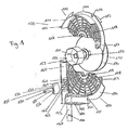
- FIG. 1 shows a schematic exploded view of a shutter side bearing part 100.
- the shutter side bearing part comprises an upper half disc 110 and a lower half disc 150. Further shows FIG. 1 a total shaft 170 and a push-up protection 130.
- the upper half disc 110 has a substantially semi-disc-shaped basic shape.
- the upper half disc 110 thus has the shape of an angular segment of 180 ° of a flat disc.
- the lower half disc 150 has a likewise substantially semi-disc-shaped basic shape.
- the upper half disc 110 and the lower half disc 150 may be assembled into a complete disc and then form the roller shutter bearing side member 100.
- the center of the upper half disk 110 is formed by an upper bearing half shell 119.
- the center of the lower half disc 150 is formed by a lower bearing half shell 159.
- the upper bearing half shell 119 and the lower bearing half shell 159 form a bearing shell for receiving a ball bearing 173 of the overall shaft 170.
- a first upper support surface 111 and a second upper support surface 112 are arranged in the circumferential or azimuthal direction of the upper half-disk 110, which extend over an azimuthal angle section of the upper half-disk 110.
- the first upper support surface 111 is perpendicular to a first surface of the upper half disc 110.
- the second upper support surface 112 is perpendicular to a second surface of the upper half disc 110, which is opposite to the first surface.
- the first upper support surface 111 and the second upper support surface 112 thus extend annularly over an angular range of the upper half-disc 110 in an outer region of the upper half-disc 110.
- the azimuth angle range swept by the first upper support surface 111 and the second upper support surface 112 may, for example, be 100 °.
- first upper support surface 111 and the second upper support surface 112 are aligned flush with an edge of the upper half disk 110.
- the first upper bearing surface 111 and the second upper bearing surface 112 merge into a nose bridge 113 extending in the radial direction of the upper half-disk 110.
- the nose bridge 113 is thus perpendicular to the upper half disc 110 and perpendicular to the first upper bearing surface 111 and the second upper bearing surface 112th
- the upper half disc 110 forms an upper comb 114.
- the upper comb 114 has a first slot 115 and a second slot 116.
- the first slot 115 is in the illustration of FIG. 1 obscured, in the representation of FIG. 2 however visible.
- the upper comb 114 has an upper web 117 on. The upper web 117 serves to connect the upper half disk 110 to the lower half disk 150.
- the first and second surfaces of the upper half disc 110 are provided with a network of stabilizing ribs 118.
- the ribs 118 are formed as concentric and radially extending webs on the surfaces of the upper half disc 110 and thus have the shape of a spider web.
- the ribs 118 cause stabilization of the upper half-disc 110.
- the upper half-disc 110 can be made of thin material without losing its torsional rigidity.
- the concentric ribs 118 of the upper half disc 110 are formed alternately protruding and set back.
- a first rib of the upper half disc 110 may protrude beyond the end of the upper half disc 110.
- the corresponding rib located on the opposite side of the upper half-disk 110 is set back from the edge of the upper half-side 110.
- the next in the axial direction of the upper half disc 110 farther outwardly concentrically arranged rib on the first surface of the upper half disc 110 is then also formed reset.
- a third, radially further outwardly concentrically extending rib on the first surface of the upper half disc 110 is in turn formed overhanging.
- the rib of this rib on the second surface of the upper half disc 110 opposite rib is in turn formed reset.
- Other patterns of recessed and overhanging ribs 118 are also possible.
- the lower half disc 150 has, in a radially outer region, extending over an azimuthal angle section, a first lower support surface 151 and a second lower support surface 156.
- the first lower support surface 151 is perpendicular to a first surface of the lower half disc 150.
- the second lower support surface 156 is perpendicular to a second surface of the lower half disc 150, which is opposite to the first surface.
- the second lower bearing surface 156 is shown in FIG FIG. 1 concealed and only in the representation of FIG. 5 visible, noticeable.
- the lower half disk 150 forms a lower comb 154.
- the lower comb has a third slot 155.
- the lower comb 154 has a lower web 157, which serves to connect the lower half disc 150 with the upper half disc 110.
- the upper land 117 on the upper half disk 110 and the lower land 157 on the lower half disk 150 are disposed on abutting surfaces of the upper half disk 110 and the lower half disk 150.
- the upper ridge 117 of the upper half disc 110 may be secured to the lower ridge 154 of the lower half disc 150.
- the lower web 157 of the lower half disc 150 may be secured to the upper comb 114 of the upper half disc 110.
- the lower half-disk 150 further comprises a contact surface 160 designed as a substantially rectangular, planar sheet metal.
- the lower contact surface 160 is attached perpendicular to the outer edge of the semi-disk-shaped portion of the lower half disk 150.
- the half-disc-shaped section is perpendicular and centered on a surface of the contact surface 160.
- the outer contour of the semi-disc-shaped portion of the lower half-disc 150 is flattened in the contact area corresponding to the half-disc shape.
- the abutment surface 160 is arranged tangentially to the semi-disc-shaped section of the lower half disc 150.
- the contact surface 160 is in a holding web 153, which is oriented in the radial direction of the semi-disc-shaped portion of the lower half disc 150 inward.
- the abutment surface 160 has on the half-disc-shaped portion of the lower half-disc 150 facing surface on a plurality of grooves 161 which are oriented perpendicular to the first and the second surface of the semi-disc-shaped portion of the lower half disc 150.
- the semi-disc-shaped portion of the lower half disc 150 has a plurality of bores 162, which are arranged next to the grooves 161 of the contact surface 160.
- a guide web 152 is placed on both surfaces of the lower comb 154 of the lower half disc 150.
- the lower comb 154 is extended to a connecting foot 165.
- the connecting foot 165 has substantially the shape of a rectangular sheet.
- a bore 166 is arranged in the connecting foot 165.
- the lower half disc 150 further includes a seat surface 163.
- the seat surface 163 has the shape of a substantially rectangular sheet.
- the seat surface 163 is attached perpendicular to the lower comb 154 and connects perpendicular to the guide web 152 at.
- the seat 163 is also oriented perpendicular to the contact surface 160.
- the seat 163 knows a slot 164.
- the semi-disc-shaped portion of the lower half disc 150 is provided on both sides with reinforcing ribs 158, which are arranged as concentric and radially extending webs on the surfaces of the lower half discs 150.
- the ribs 158 of the lower half disc 150 as the ribs 118 of the upper half disc 110 are formed alternately protruding and reset. Where a rib of the upper half disc 110 projects beyond the edge of the upper half disc 110, a rib of the lower half disc 150 is recessed. Where a rib of the upper half disc 110 is recessed, a rib of the lower half disc 150 projects beyond the edge of the lower half disc 150.
- the ribs 118 of the upper half disc 110 and the ribs 158 of the lower half disc 150 form a continuous net concentrically around the bearing shell and extending radially from the bearing shell outwardly extending webs , Since the ribs of the upper half disk 110 and the lower half disk 150 are formed alternately protruding and set back, the upper half disk 110 and the upper half disk 150 are secured in the assembled state against mutual displacement in the axial direction of the roller shutter bearing side part 110.
- total shaft 170 includes an axis 171.
- the axis 171 may be performed for example as a square axle of a square tube.
- a roller shutter armor shaft 172 is arranged on the square axle 171. In FIG. 1 only a first portion of the roller shutter shell shaft 172 is shown. On the roller shutter shell shaft 172 of the existing slats roller shutter of the shutter is wound up.
- a ball bearing 173 is arranged on the square axle 171.
- the ball bearing 173 is dimensioned such that it can be received in the bearing shell of the roller shutter bearing side part 100 formed by the upper bearing half shell 119 and the lower bearing half shell 159.
- the ball bearing 173 causes the total shaft 170 can be rotatably mounted about the longitudinal axis of the square shaft 171 in the roller shutter bearing side part 100.
- a belt reel 174 is arranged on the square axle 171.
- a belt is wound, which serves to raise and lower the shutter.
- the belt reel 174 can be displaced in the axial direction with the square axle 171 and fixed at a desired position.
- a belt drive, a crank or a motor can be provided.
- the anti-lift device 130 comprises a wedge body 131.
- the wedge body 131 has three surfaces with a substantially rectangular basic shape and two opposing surfaces with a substantially triangular basic shape.
- the two triangular surfaces of the wedge body 131 each have two pins 132, which are arranged perpendicular to the two triangular surfaces of the wedge body 131.
- a through hole 133 extends from the first triangular surface of the wedge body 131 to the second triangular surface of the wedge body 131.
- two beads 135 are arranged from the first one triangular surface 131 extend to the second triangular surface of the wedge body 131.
- the beads 135 are arranged at the level of the pins 123. That is, an imaginary connecting line from a first pin 132 of a first triangular surface of the wedge body 131 to a first bead 135 parallel to a second imaginary connecting line to a second pin 132 disposed on the first triangular surface of the wedge body is oriented to a second bead 135 ,
- the anti-push device 130 can be fastened by means of a screw 134 to the lower half-disc 150 of the roller shutter bearing side part 100.
- a screw 134 arranged on one of the triangular surfaces of the wedge body 131 pin 132 can be inserted into two of the holes 162 of the lower half disc 150.
- the beads 135 arranged on one of the rectangular surfaces of the wedge body 131 come to lie in two grooves 161 of the contact surface 160 of the lower half disk 150.
- the surface of the wedge body 131 provided with beads 135 thus bears against the abutment surface 160 of the lower half disk 150.
- One of the triangular surfaces of the wedge body 131 abuts against the half-disk-shaped portion of the lower half disk 150.
- the screw 134 is guided through the through hole 133 of the wedge body 131 and screwed into one of the holes 162 of the lower half disc 150.
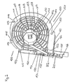
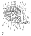
- the anti-push device 131 can be mounted to different positions of the lower half disc 150. This is schematic in the Figures 2 and 3 shown.
- Figures 2 and 3 show schematic representations of the shutter side bearing part 100 with assembled upper half disc 110 and lower half disc 150 and inserted total shaft 170.
- a roller shutter 201 is attached via a leaf spring 201, the first and second lamella 202, 203 are partially shown.
- the louvers 202, 203 of the roller shutter shell the entire length of the roller shutter width, for example, up to 340 cm.
- the roller shutter shell shaft 173 has a corresponding length.
- the roller shutter armor can also be connected to the roller shutter armature shaft 172 via a plurality of leaf springs 201. The roller shutter is guided along between the contact surface 160 and the guide web 152 of the lower half disc 150.
- the push-up safety device 130 is mounted at a first position of the lower half-disc 150, which is closer to the overall shaft 170.
- the push-up safety device 130 is mounted at a second position of the lower half-disc 150, which has a greater distance from the overall shaft 170.
- the wedge body 131 of the anti-push device 130 is oriented so that the first louver 202 of the roller shutter under the roller 131 engages when trying to push the roller shutter from the outside upwards.
- the leaf spring 201 pulls the uppermost louver 202 of the roller shutter over the wedge body 131 of the push-up protection device 130 so that the roller shutter shell can be wound onto the roller shutter sheave shaft 172.
- the first louver 202 may also be provided with an additional Verhakerelement that assures a secure hooking of the uppermost lamella 202 on the wedge body 131 when the roller shutter is pushed from the outside upwards.
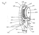
- FIG. 4 shows a section through a shutter box 300, which is located above a window.
- the living space side shutter pocket 301 was in the representation of FIG. 4 removed from the shutter box 300.
- FIG. 4 a section through an upper window stock 310 and an upper window sash 311 with window pane 312 enclosed therein.
- the insulating body 210 consists of a substantially rectangular mat of insulating material, for example, Cerchialica, a substantially rectangular mat of insulating material, for example, Cerchialica, a plurality of wedge-shaped incisions 214, which run parallel to two opposite outer edges of the insulating body 210.
- the notches 214 of the insulating body 210 allow the insulating body 210 to curve into a cylindrical shell cutout. Due to the curvature of the insulating body 210, the wedge-shaped incisions 214 are closed, so that the inner surface of the cylinder jacket formed by the insulating body 210 forms a closed surface.
- a bias and thereby increased torsional stiffness of the insulating 210 can be effected.
- a first tube 211, a second tube 212 and a third tube 213 incorporated, for example cast.
- the first, second and third tubes 211, 212, 213 are oriented parallel to the notches 214.
- the tubes 211, 212, 213 each have retaining means 215 at both ends.
- the holding means 215 can be designed, for example, as buttons or as screw heads. They are in FIG. 5 shown.
- the old shutters in the shutter box 300 including bearings and side panels is removed.
- the old roller shutter guide rails on the outside of the window are replaced by new roller shutter rails. That already existing windows can remain together with the window stock 310 in the window opening.
- the lower half disks 150 of the left and right roller shutter bearing side members 100 are inserted into the old shutter box.
- Shutter bearing side member 100 described is symmetrical with respect to a mirror on a plane passing through upper half-disc 110 and lower half-disc 150 level. Therefore, the roller shutter bearing side member 100 can be used both as a left and a right roller shutter bearing side part.
- Each lower half disc 150 is inserted into the roller shutter box 300 such that the connecting leg 165 of the lower half disc 150 engages the roller shutter rail replaced in the previous step. Through the bore 166, the connecting foot 165 can be screwed to the roller shutter rail.
- the seat 163 of the lower half disc 150 sits on the window sump 310 and can be screwed through the slot 164 with this.
- the contact surface 160 of the lower half-disc 150 bears against the wall of the roller shutter box 300 facing the outside of the house. Between the wall of the roller shutter box 300 and the contact surface 160 of the lower half disc 150, an insulating and / or adhesive material may be provided. Then, the roller shutter bearing side members 100 are properly positioned in the roller shutter box 300.
- the new roller shutter armor is inserted from the side of the roller shutter box 300 into the roller shutter guide rails.
- the total shaft 170 is inserted into the lower bearing half shells 159 of the two lower half disks 150.
- the roller shutter shell shaft 172 and two ball bearings 173 are already arranged.
- the two ball bearings 173 come to lie in the two lower bearing half-shells 159.
- the belt reel 174 in the shutter box 300 inserted and attached to one end of the square axle 171.
- the belt reel 174 can be moved axially with the square axle 171 to the position of a already existing in the masonry or in the shutter box 300 Gurt miclasses and locked there.
- a belt is passed through the Gurt barnlass and connected to the belt reel 174.
- roller shutter armor is connected via leaf springs 201 with the arranged between the two ball bearings 173 roller shutter shell shaft 172.
- the push-up protection 130 is connected directly above the uppermost louver 202 of the roller shutter with the lower half disc 150 of the roller shutter bearing side parts 100.
- both shutter side bearing parts 100 are provided with push-up fuses 130.
- the anti-push device 130 can be mounted at different positions of the lower half-disc 150, the anti-push device 130 can be adapted to different slat widths and different window heights. Since the push-up protection 130 is always mounted directly above the uppermost slat 202, the roller shutter armor can be pushed from the outside by not even a slat width upwards.
- the upper half disks 110 of the new roller shutter bearing side parts 100 are placed on the lower half disks 150 of the roller shutter bearing side parts 100.
- the nose bridge 113 of the upper half disc 110 is under the holding web 153 of the lower half disc 150 mounted and set the upper half disc 110 on the lower half disc 150 such that the upper bearing half shell 119, the ball bearing 173 of the overall shaft 170 receives.
- the upper land 117 of the upper half disk 110 is connected to the lower half disk 150.
- the lower web 157 of the lower half disk is connected to the upper half disk 110.
- the shutter side bearing part 100 is completely assembled.
- the insulating body 210 is set over the shutter side bearing parts 100.
- the insulating body 210 is first placed over the upper half disks 110 of the two roller shutter bearing side parts 100. In this case, the insulating body 210 comes to lie on the first upper bearing surface 111 of the upper right half disc and on the second upper bearing surface 112 of the left upper half disc.
- the holding means 215 of the first tube 211 of the insulating body 210 are suspended in the first slots 115 of the two upper half discs 110.
- the holding means 215 of the second tube 212 of the insulating body 210 are suspended in the second slots 116 of the two upper half discs 110. This is in FIG. 5 visible, noticeable.
- the insulating body 210 is then further bent down to the two lower half discs 150.
- the insulating body 210 comes to rest on the first lower support surface 151 of the lower right half disk and the second lower support surface 156 of the lower left half disk.
- the holding means 215 of the third tube 213 of the insulating body 210 are clipped into the third slots 155 of the lower half discs 150.
- the insulating body 210 surrounds the roller shutter shell 172 cylinder jacket-shaped. A first end of the insulating body 210 abuts against the retaining webs 153 of the two lower half disks 150. A second end of the insulating body 210 is located on the guide webs 152 of two lower half discs 150 at. As a result, the space surrounding the roller shutter shell 172 inside the insulating body 210 is completely separated from the space outside of the insulating body 210. Cold outside air only penetrates into the space inside the insulating body 210. The outside of the insulating body 210 in the shutter box 300 located air can serve as insulating air cushion.
- the new roller shutter including insulation 210 and push-up protection 130 is fully assembled.
- the old shutter box lid 301 may be further used. If necessary, the old roller shutter cover 301 may be provided with an additional insulating pad.
Landscapes
- Engineering & Computer Science (AREA)
- Structural Engineering (AREA)
- Architecture (AREA)
- Civil Engineering (AREA)
- Operating, Guiding And Securing Of Roll- Type Closing Members (AREA)
- Rolls And Other Rotary Bodies (AREA)
Applications Claiming Priority (1)
| Application Number | Priority Date | Filing Date | Title |
|---|---|---|---|
| DE200820007039 DE202008007039U1 (de) | 2008-05-24 | 2008-05-24 | Rollladen |
Publications (3)
| Publication Number | Publication Date |
|---|---|
| EP2123858A2 true EP2123858A2 (fr) | 2009-11-25 |
| EP2123858A3 EP2123858A3 (fr) | 2012-08-15 |
| EP2123858B1 EP2123858B1 (fr) | 2013-10-02 |
Family
ID=40847620
Family Applications (2)
| Application Number | Title | Priority Date | Filing Date |
|---|---|---|---|
| EP20090159392 Not-in-force EP2123858B1 (fr) | 2008-05-24 | 2009-05-05 | Stores |
| EP20090159391 Not-in-force EP2123857B1 (fr) | 2008-05-24 | 2009-05-05 | Stores |
Family Applications After (1)
| Application Number | Title | Priority Date | Filing Date |
|---|---|---|---|
| EP20090159391 Not-in-force EP2123857B1 (fr) | 2008-05-24 | 2009-05-05 | Stores |
Country Status (2)
| Country | Link |
|---|---|
| EP (2) | EP2123858B1 (fr) |
| DE (1) | DE202008007039U1 (fr) |
Families Citing this family (6)
| Publication number | Priority date | Publication date | Assignee | Title |
|---|---|---|---|---|
| DE202008016858U1 (de) * | 2008-12-19 | 2010-02-18 | Detenhoff, Reiner | Rollraumverkleidungsbausatz sowie eine Isoliermatte zur Rollraumverkleidung |
| DE202009006640U1 (de) * | 2009-05-07 | 2009-07-23 | Alfred Schellenberg Gmbh | Vorbau-Rollladen zum Schutz von Öffnungen, insbesondere von Fenstern, Türen o.dgl. |
| DE102009052009B4 (de) | 2009-11-05 | 2012-03-08 | Roma Kg | Renovierungsrolladen, Wickelwelleneinhausung, Einhausungsbauteil und Befestigungsadapter dafuer |
| DE102009052010B4 (de) | 2009-11-05 | 2012-02-16 | Roma Kg | Renovierungsrollladen und Seitenteilmodul dafür |
| DE202012100036U1 (de) | 2012-01-05 | 2012-02-27 | Alulux Beckhoff Gmbh & Co. Kg | Rollladen |
| FR3009840B1 (fr) * | 2013-08-22 | 2015-09-18 | Zurfluh Feller | Coque d'isolation thermique et installation de volet roulant comprenant une telle coque |
Citations (1)
| Publication number | Priority date | Publication date | Assignee | Title |
|---|---|---|---|---|
| DE102005061172A1 (de) | 2005-12-21 | 2007-06-28 | Bernd Beck | Flexibles Dämmsystem |
Family Cites Families (14)
| Publication number | Priority date | Publication date | Assignee | Title |
|---|---|---|---|---|
| DE68663C (de) * | A. B. DRAUTZ in Stuttgart. Vom vj. Juli 1S92 ab | Selbsttätiger Rollladenverschlufs | ||
| DE1101458B (de) * | 1956-07-31 | 1961-03-09 | Siemens Elektrogeraete Gmbh | Rolltuer fuer einen Kuehlschrank oder Waermeschrank |
| DE1867167U (de) * | 1962-11-28 | 1963-02-14 | Binne & Sohn | Waermedaemmende belagplatte fuer gewoelbte dachflaechen. |
| DE7004259U (de) * | 1970-02-07 | 1970-05-14 | Wirth Hans | Rolladenwickelwalzenlagerung. |
| DE2518356A1 (de) * | 1975-04-25 | 1976-11-04 | Wolfgang Jatho | Rolladen mit sperrvorrichtung gegen unbefugtes hochschieben von aussen |
| JPS5273510U (fr) * | 1975-11-28 | 1977-06-01 | ||
| DE7924106U1 (de) * | 1979-08-24 | 1980-01-10 | Kindervater, Guenter, 2800 Bremen | Rolladen zum abdecken von bauwerksoeffnungen |
| EP0348791A3 (fr) * | 1988-06-28 | 1991-05-29 | Rolladen Braun KG | Carter de store |
| ATE157734T1 (de) * | 1992-03-18 | 1997-09-15 | Glatz Ag | Lagerbock einer schwimmbadabdeck-anlage |
| DE9306337U1 (de) * | 1993-04-27 | 1993-07-22 | Losberger Sonnenschutz Gmbh + Co, 7100 Heilbronn | Kupplungslager für geteilte, aufwickelbare Behänge von Beschattungsanlagen |
| DE4409416C2 (de) * | 1994-03-18 | 1999-06-10 | Gruenzweig & Hartmann | Mineralwolle-Dämmplatte, ihre Verwendungen und Verfahren zu ihrer Herstellung |
| DE29806310U1 (de) * | 1998-04-07 | 1998-07-30 | Home-Fertigelemente GmbH, 59872 Meschede | Rolladenkasten mit Wärmedämmkörper |
| DE20007657U1 (de) * | 2000-04-27 | 2001-09-27 | D & M Rolladentechnik GmbH, 56204 Hillscheid | Vorsatzrolladenkasten |
| DE10132766A1 (de) * | 2001-07-10 | 2003-01-30 | Bernd Beck | Einrichtung zur nachträglichen Wärmeisolierung von Hohlräumen |
-
2008
- 2008-05-24 DE DE200820007039 patent/DE202008007039U1/de not_active Expired - Lifetime
-
2009
- 2009-05-05 EP EP20090159392 patent/EP2123858B1/fr not_active Not-in-force
- 2009-05-05 EP EP20090159391 patent/EP2123857B1/fr not_active Not-in-force
Patent Citations (1)
| Publication number | Priority date | Publication date | Assignee | Title |
|---|---|---|---|---|
| DE102005061172A1 (de) | 2005-12-21 | 2007-06-28 | Bernd Beck | Flexibles Dämmsystem |
Also Published As
| Publication number | Publication date |
|---|---|
| EP2123858B1 (fr) | 2013-10-02 |
| EP2123857A3 (fr) | 2012-08-08 |
| EP2123858A3 (fr) | 2012-08-15 |
| DE202008007039U1 (de) | 2009-07-09 |
| EP2123857A2 (fr) | 2009-11-25 |
| EP2123857B1 (fr) | 2013-09-11 |
Similar Documents
| Publication | Publication Date | Title |
|---|---|---|
| EP2039871B1 (fr) | Stores et articulation correspondante | |
| DE69519764T2 (de) | Jalousierbarer Rolladen | |
| EP2123858B1 (fr) | Stores | |
| WO1994002705A1 (fr) | Volet roulant du type jalousie | |
| EP3165701B1 (fr) | Élément d'aération pour fenêtre comprenant un clapet agissant comme une chicane | |
| EP1992756B1 (fr) | Toit à lamelles | |
| DE19854552C2 (de) | Rolladenkasten mit Wärmedämmkörper | |
| DE202021104709U1 (de) | Externe Abschirmungsanordnung für eine mehrere Fenstereinheiten umfassende Dachfensteranordnung | |
| EP1799951A1 (fr) | Volet roulant a fonction store venitien, element et procede de fabrication associe | |
| EP1898041B1 (fr) | Procedé et dispositif de montage d'accessoires sur cadres de bâtiments | |
| EP1992757B1 (fr) | Toit à lamelles | |
| CH694436A5 (de) | Rolladen. | |
| EP2677110B1 (fr) | Rideau de protection solaire | |
| EP2754844A2 (fr) | Système à lamelles | |
| DE202009012128U1 (de) | Jalousieklappensystem | |
| EP1087094B1 (fr) | Volet roulant pour ouvertures de bâtiments, et dont la forme diffère de la forme rectangulaire | |
| DE20305389U1 (de) | Vorrichtung zum Verbinden eines Rollvorhangs mit einer Wickelwelle | |
| DE202017104941U1 (de) | Seitenteil für einen Aufnahmekasten zum Einbau in Fenster- oder Türöffnungen und Aufnahmekasten zum Einbau in Fenster- oder Türöffnungen mit einem solchen Seitenteil | |
| DE102023128268A1 (de) | Lamelle für einen Rollladen, Rollladen umfassend mindestens eine Lamelle, Rahmen mit Rollladen und Zarge mit Rollladen | |
| DE102023132684A1 (de) | Befestigungsvorrichtung für einen Aufsatzrollladenkasten, Aufsatzrollladenkasten sowie Fenster / Tür mit einem Aufsatzrollladenkasten | |
| EP1577478B9 (fr) | Renvoi d'angle avec pièces de guidage | |
| DE202016100905U1 (de) | Seilklemmenanordnung | |
| CH690968A5 (de) | Fensterladen mit Insektenschutz. | |
| DE202021104711U1 (de) | Externe Abschirmungsanordnung mit Lichtdichtheitsmitteln für eine mehrere Fenstereinheiten umfassende Dachfensteranordnung | |
| DE102019103662A1 (de) | Verbundraffstore über Eck |
Legal Events
| Date | Code | Title | Description |
|---|---|---|---|
| PUAI | Public reference made under article 153(3) epc to a published international application that has entered the european phase |
Free format text: ORIGINAL CODE: 0009012 |
|
| AK | Designated contracting states |
Kind code of ref document: A2 Designated state(s): AT BE BG CH CY CZ DE DK EE ES FI FR GB GR HR HU IE IS IT LI LT LU LV MC MK MT NL NO PL PT RO SE SI SK TR |
|
| RIC1 | Information provided on ipc code assigned before grant |
Ipc: E06B 9/174 20060101AFI20120321BHEP |
|
| PUAL | Search report despatched |
Free format text: ORIGINAL CODE: 0009013 |
|
| AK | Designated contracting states |
Kind code of ref document: A3 Designated state(s): AT BE BG CH CY CZ DE DK EE ES FI FR GB GR HR HU IE IS IT LI LT LU LV MC MK MT NL NO PL PT RO SE SI SK TR |
|
| RIC1 | Information provided on ipc code assigned before grant |
Ipc: E06B 9/174 20060101AFI20120709BHEP |
|
| 17P | Request for examination filed |
Effective date: 20130208 |
|
| GRAP | Despatch of communication of intention to grant a patent |
Free format text: ORIGINAL CODE: EPIDOSNIGR1 |
|
| INTG | Intention to grant announced |
Effective date: 20130416 |
|
| GRAS | Grant fee paid |
Free format text: ORIGINAL CODE: EPIDOSNIGR3 |
|
| GRAA | (expected) grant |
Free format text: ORIGINAL CODE: 0009210 |
|
| AK | Designated contracting states |
Kind code of ref document: B1 Designated state(s): AT BE BG CH CY CZ DE DK EE ES FI FR GB GR HR HU IE IS IT LI LT LU LV MC MK MT NL NO PL PT RO SE SI SK TR |
|
| REG | Reference to a national code |
Ref country code: GB Ref legal event code: FG4D Free format text: NOT ENGLISH |
|
| REG | Reference to a national code |
Ref country code: CH Ref legal event code: EP Ref country code: AT Ref legal event code: REF Ref document number: 634722 Country of ref document: AT Kind code of ref document: T Effective date: 20131015 |
|
| REG | Reference to a national code |
Ref country code: IE Ref legal event code: FG4D Free format text: LANGUAGE OF EP DOCUMENT: GERMAN |
|
| REG | Reference to a national code |
Ref country code: DE Ref legal event code: R096 Ref document number: 502009008084 Country of ref document: DE Effective date: 20131128 |
|
| REG | Reference to a national code |
Ref country code: NL Ref legal event code: VDEP Effective date: 20131002 |
|
| PG25 | Lapsed in a contracting state [announced via postgrant information from national office to epo] |
Ref country code: SI Free format text: LAPSE BECAUSE OF FAILURE TO SUBMIT A TRANSLATION OF THE DESCRIPTION OR TO PAY THE FEE WITHIN THE PRESCRIBED TIME-LIMIT Effective date: 20131002 |
|
| REG | Reference to a national code |
Ref country code: LT Ref legal event code: MG4D |
|
| PG25 | Lapsed in a contracting state [announced via postgrant information from national office to epo] |
Ref country code: FI Free format text: LAPSE BECAUSE OF FAILURE TO SUBMIT A TRANSLATION OF THE DESCRIPTION OR TO PAY THE FEE WITHIN THE PRESCRIBED TIME-LIMIT Effective date: 20131002 Ref country code: LT Free format text: LAPSE BECAUSE OF FAILURE TO SUBMIT A TRANSLATION OF THE DESCRIPTION OR TO PAY THE FEE WITHIN THE PRESCRIBED TIME-LIMIT Effective date: 20131002 Ref country code: IS Free format text: LAPSE BECAUSE OF FAILURE TO SUBMIT A TRANSLATION OF THE DESCRIPTION OR TO PAY THE FEE WITHIN THE PRESCRIBED TIME-LIMIT Effective date: 20140202 Ref country code: CZ Free format text: LAPSE BECAUSE OF FAILURE TO SUBMIT A TRANSLATION OF THE DESCRIPTION OR TO PAY THE FEE WITHIN THE PRESCRIBED TIME-LIMIT Effective date: 20131002 Ref country code: SE Free format text: LAPSE BECAUSE OF FAILURE TO SUBMIT A TRANSLATION OF THE DESCRIPTION OR TO PAY THE FEE WITHIN THE PRESCRIBED TIME-LIMIT Effective date: 20131002 Ref country code: NL Free format text: LAPSE BECAUSE OF FAILURE TO SUBMIT A TRANSLATION OF THE DESCRIPTION OR TO PAY THE FEE WITHIN THE PRESCRIBED TIME-LIMIT Effective date: 20131002 Ref country code: HR Free format text: LAPSE BECAUSE OF FAILURE TO SUBMIT A TRANSLATION OF THE DESCRIPTION OR TO PAY THE FEE WITHIN THE PRESCRIBED TIME-LIMIT Effective date: 20131002 Ref country code: NO Free format text: LAPSE BECAUSE OF FAILURE TO SUBMIT A TRANSLATION OF THE DESCRIPTION OR TO PAY THE FEE WITHIN THE PRESCRIBED TIME-LIMIT Effective date: 20140102 |
|
| PG25 | Lapsed in a contracting state [announced via postgrant information from national office to epo] |
Ref country code: ES Free format text: LAPSE BECAUSE OF FAILURE TO SUBMIT A TRANSLATION OF THE DESCRIPTION OR TO PAY THE FEE WITHIN THE PRESCRIBED TIME-LIMIT Effective date: 20131002 Ref country code: PL Free format text: LAPSE BECAUSE OF FAILURE TO SUBMIT A TRANSLATION OF THE DESCRIPTION OR TO PAY THE FEE WITHIN THE PRESCRIBED TIME-LIMIT Effective date: 20131002 Ref country code: CY Free format text: LAPSE BECAUSE OF FAILURE TO SUBMIT A TRANSLATION OF THE DESCRIPTION OR TO PAY THE FEE WITHIN THE PRESCRIBED TIME-LIMIT Effective date: 20131002 Ref country code: LV Free format text: LAPSE BECAUSE OF FAILURE TO SUBMIT A TRANSLATION OF THE DESCRIPTION OR TO PAY THE FEE WITHIN THE PRESCRIBED TIME-LIMIT Effective date: 20131002 |
|
| PG25 | Lapsed in a contracting state [announced via postgrant information from national office to epo] |
Ref country code: PT Free format text: LAPSE BECAUSE OF FAILURE TO SUBMIT A TRANSLATION OF THE DESCRIPTION OR TO PAY THE FEE WITHIN THE PRESCRIBED TIME-LIMIT Effective date: 20140203 |
|
| REG | Reference to a national code |
Ref country code: DE Ref legal event code: R097 Ref document number: 502009008084 Country of ref document: DE |
|
| PG25 | Lapsed in a contracting state [announced via postgrant information from national office to epo] |
Ref country code: EE Free format text: LAPSE BECAUSE OF FAILURE TO SUBMIT A TRANSLATION OF THE DESCRIPTION OR TO PAY THE FEE WITHIN THE PRESCRIBED TIME-LIMIT Effective date: 20131002 |
|
| PLBE | No opposition filed within time limit |
Free format text: ORIGINAL CODE: 0009261 |
|
| STAA | Information on the status of an ep patent application or granted ep patent |
Free format text: STATUS: NO OPPOSITION FILED WITHIN TIME LIMIT |
|
| PG25 | Lapsed in a contracting state [announced via postgrant information from national office to epo] |
Ref country code: RO Free format text: LAPSE BECAUSE OF FAILURE TO SUBMIT A TRANSLATION OF THE DESCRIPTION OR TO PAY THE FEE WITHIN THE PRESCRIBED TIME-LIMIT Effective date: 20131002 Ref country code: SK Free format text: LAPSE BECAUSE OF FAILURE TO SUBMIT A TRANSLATION OF THE DESCRIPTION OR TO PAY THE FEE WITHIN THE PRESCRIBED TIME-LIMIT Effective date: 20131002 Ref country code: IT Free format text: LAPSE BECAUSE OF FAILURE TO SUBMIT A TRANSLATION OF THE DESCRIPTION OR TO PAY THE FEE WITHIN THE PRESCRIBED TIME-LIMIT Effective date: 20131002 |
|
| 26N | No opposition filed |
Effective date: 20140703 |
|
| PG25 | Lapsed in a contracting state [announced via postgrant information from national office to epo] |
Ref country code: DK Free format text: LAPSE BECAUSE OF FAILURE TO SUBMIT A TRANSLATION OF THE DESCRIPTION OR TO PAY THE FEE WITHIN THE PRESCRIBED TIME-LIMIT Effective date: 20131002 |
|
| REG | Reference to a national code |
Ref country code: DE Ref legal event code: R097 Ref document number: 502009008084 Country of ref document: DE Effective date: 20140703 |
|
| PG25 | Lapsed in a contracting state [announced via postgrant information from national office to epo] |
Ref country code: LU Free format text: LAPSE BECAUSE OF FAILURE TO SUBMIT A TRANSLATION OF THE DESCRIPTION OR TO PAY THE FEE WITHIN THE PRESCRIBED TIME-LIMIT Effective date: 20140505 |
|
| GBPC | Gb: european patent ceased through non-payment of renewal fee |
Effective date: 20140505 |
|
| PG25 | Lapsed in a contracting state [announced via postgrant information from national office to epo] |
Ref country code: MC Free format text: LAPSE BECAUSE OF FAILURE TO SUBMIT A TRANSLATION OF THE DESCRIPTION OR TO PAY THE FEE WITHIN THE PRESCRIBED TIME-LIMIT Effective date: 20131002 |
|
| REG | Reference to a national code |
Ref country code: IE Ref legal event code: MM4A |
|
| PG25 | Lapsed in a contracting state [announced via postgrant information from national office to epo] |
Ref country code: IE Free format text: LAPSE BECAUSE OF NON-PAYMENT OF DUE FEES Effective date: 20140505 |
|
| PG25 | Lapsed in a contracting state [announced via postgrant information from national office to epo] |
Ref country code: GB Free format text: LAPSE BECAUSE OF NON-PAYMENT OF DUE FEES Effective date: 20140505 |
|
| PG25 | Lapsed in a contracting state [announced via postgrant information from national office to epo] |
Ref country code: MT Free format text: LAPSE BECAUSE OF FAILURE TO SUBMIT A TRANSLATION OF THE DESCRIPTION OR TO PAY THE FEE WITHIN THE PRESCRIBED TIME-LIMIT Effective date: 20131002 |
|
| PG25 | Lapsed in a contracting state [announced via postgrant information from national office to epo] |
Ref country code: NO Free format text: LAPSE BECAUSE OF FAILURE TO SUBMIT A TRANSLATION OF THE DESCRIPTION OR TO PAY THE FEE WITHIN THE PRESCRIBED TIME-LIMIT Effective date: 20140101 |
|
| REG | Reference to a national code |
Ref country code: FR Ref legal event code: PLFP Year of fee payment: 8 |
|
| PG25 | Lapsed in a contracting state [announced via postgrant information from national office to epo] |
Ref country code: BG Free format text: LAPSE BECAUSE OF FAILURE TO SUBMIT A TRANSLATION OF THE DESCRIPTION OR TO PAY THE FEE WITHIN THE PRESCRIBED TIME-LIMIT Effective date: 20131002 Ref country code: GR Free format text: LAPSE BECAUSE OF FAILURE TO SUBMIT A TRANSLATION OF THE DESCRIPTION OR TO PAY THE FEE WITHIN THE PRESCRIBED TIME-LIMIT Effective date: 20140103 |
|
| PG25 | Lapsed in a contracting state [announced via postgrant information from national office to epo] |
Ref country code: BE Free format text: LAPSE BECAUSE OF FAILURE TO SUBMIT A TRANSLATION OF THE DESCRIPTION OR TO PAY THE FEE WITHIN THE PRESCRIBED TIME-LIMIT Effective date: 20140531 Ref country code: TR Free format text: LAPSE BECAUSE OF FAILURE TO SUBMIT A TRANSLATION OF THE DESCRIPTION OR TO PAY THE FEE WITHIN THE PRESCRIBED TIME-LIMIT Effective date: 20131002 Ref country code: HU Free format text: LAPSE BECAUSE OF FAILURE TO SUBMIT A TRANSLATION OF THE DESCRIPTION OR TO PAY THE FEE WITHIN THE PRESCRIBED TIME-LIMIT; INVALID AB INITIO Effective date: 20090505 |
|
| REG | Reference to a national code |
Ref country code: FR Ref legal event code: PLFP Year of fee payment: 9 |
|
| REG | Reference to a national code |
Ref country code: FR Ref legal event code: PLFP Year of fee payment: 10 |
|
| PG25 | Lapsed in a contracting state [announced via postgrant information from national office to epo] |
Ref country code: MK Free format text: LAPSE BECAUSE OF FAILURE TO SUBMIT A TRANSLATION OF THE DESCRIPTION OR TO PAY THE FEE WITHIN THE PRESCRIBED TIME-LIMIT Effective date: 20131002 |
|
| PGFP | Annual fee paid to national office [announced via postgrant information from national office to epo] |
Ref country code: FR Payment date: 20200519 Year of fee payment: 12 Ref country code: DE Payment date: 20200516 Year of fee payment: 12 Ref country code: CH Payment date: 20200522 Year of fee payment: 12 |
|
| PGFP | Annual fee paid to national office [announced via postgrant information from national office to epo] |
Ref country code: AT Payment date: 20200528 Year of fee payment: 12 |
|
| REG | Reference to a national code |
Ref country code: DE Ref legal event code: R119 Ref document number: 502009008084 Country of ref document: DE |
|
| REG | Reference to a national code |
Ref country code: CH Ref legal event code: PL |
|
| REG | Reference to a national code |
Ref country code: AT Ref legal event code: MM01 Ref document number: 634722 Country of ref document: AT Kind code of ref document: T Effective date: 20210505 |
|
| PG25 | Lapsed in a contracting state [announced via postgrant information from national office to epo] |
Ref country code: LI Free format text: LAPSE BECAUSE OF NON-PAYMENT OF DUE FEES Effective date: 20210531 Ref country code: AT Free format text: LAPSE BECAUSE OF NON-PAYMENT OF DUE FEES Effective date: 20210505 Ref country code: CH Free format text: LAPSE BECAUSE OF NON-PAYMENT OF DUE FEES Effective date: 20210531 |
|
| PG25 | Lapsed in a contracting state [announced via postgrant information from national office to epo] |
Ref country code: DE Free format text: LAPSE BECAUSE OF NON-PAYMENT OF DUE FEES Effective date: 20211201 |
|
| PG25 | Lapsed in a contracting state [announced via postgrant information from national office to epo] |
Ref country code: FR Free format text: LAPSE BECAUSE OF NON-PAYMENT OF DUE FEES Effective date: 20210531 |