EP2126268B1 - Commande de moteur d'appareil de forage - Google Patents
Commande de moteur d'appareil de forage Download PDFInfo
- Publication number
- EP2126268B1 EP2126268B1 EP20080702151 EP08702151A EP2126268B1 EP 2126268 B1 EP2126268 B1 EP 2126268B1 EP 20080702151 EP20080702151 EP 20080702151 EP 08702151 A EP08702151 A EP 08702151A EP 2126268 B1 EP2126268 B1 EP 2126268B1
- Authority
- EP
- European Patent Office
- Prior art keywords
- power
- rig
- drawworks
- engine
- controller
- Prior art date
- Legal status (The legal status is an assumption and is not a legal conclusion. Google has not performed a legal analysis and makes no representation as to the accuracy of the status listed.)
- Active
Links
Images





Classifications
-
- F—MECHANICAL ENGINEERING; LIGHTING; HEATING; WEAPONS; BLASTING
- F02—COMBUSTION ENGINES; HOT-GAS OR COMBUSTION-PRODUCT ENGINE PLANTS
- F02D—CONTROLLING COMBUSTION ENGINES
- F02D41/00—Electrical control of supply of combustible mixture or its constituents
- F02D41/02—Circuit arrangements for generating control signals
- F02D41/14—Introducing closed-loop corrections
- F02D41/1438—Introducing closed-loop corrections using means for determining characteristics of the combustion gases; Sensors therefor
- F02D41/1444—Introducing closed-loop corrections using means for determining characteristics of the combustion gases; Sensors therefor characterised by the characteristics of the combustion gases
- F02D41/1446—Introducing closed-loop corrections using means for determining characteristics of the combustion gases; Sensors therefor characterised by the characteristics of the combustion gases the characteristics being exhaust temperatures
-
- E—FIXED CONSTRUCTIONS
- E21—EARTH OR ROCK DRILLING; MINING
- E21B—EARTH OR ROCK DRILLING; OBTAINING OIL, GAS, WATER, SOLUBLE OR MELTABLE MATERIALS OR A SLURRY OF MINERALS FROM WELLS
- E21B19/00—Handling rods, casings, tubes or the like outside the borehole, e.g. in the derrick; Apparatus for feeding the rods or cables
- E21B19/08—Apparatus for feeding the rods or cables; Apparatus for increasing or decreasing the pressure on the drilling tool; Apparatus for counterbalancing the weight of the rods
- E21B19/084—Apparatus for feeding the rods or cables; Apparatus for increasing or decreasing the pressure on the drilling tool; Apparatus for counterbalancing the weight of the rods with flexible drawing means, e.g. cables
-
- F—MECHANICAL ENGINEERING; LIGHTING; HEATING; WEAPONS; BLASTING
- F02—COMBUSTION ENGINES; HOT-GAS OR COMBUSTION-PRODUCT ENGINE PLANTS
- F02D—CONTROLLING COMBUSTION ENGINES
- F02D41/00—Electrical control of supply of combustible mixture or its constituents
- F02D41/02—Circuit arrangements for generating control signals
- F02D41/14—Introducing closed-loop corrections
- F02D41/1497—With detection of the mechanical response of the engine
-
- F—MECHANICAL ENGINEERING; LIGHTING; HEATING; WEAPONS; BLASTING
- F02—COMBUSTION ENGINES; HOT-GAS OR COMBUSTION-PRODUCT ENGINE PLANTS
- F02D—CONTROLLING COMBUSTION ENGINES
- F02D2250/00—Engine control related to specific problems or objectives
- F02D2250/18—Control of the engine output torque
Definitions
- the present invention relates to a system for controlling power load on a rig engine, and to a wellbore rig comprising such a system.
- the invention relates to: controlling generator engines, and in certain particular aspects, to controlling wellbore rig generator engines to control gas emissions that form; to power systems for rigs used in wellbore operations, e.g. drilling; to methods and systems and methods for recovering and using power generated by rig apparatuses; and to enhancing the quality of power used on a rig.
- Rigs used for wellbore operations use a wide variety of tools, apparatuses, appliances, systems and devices that use electrical power.
- power is supplied by one or more generators that run on diesel fuel or other hydrocarbon fuel.
- Such rigs including, but not limited to, drilling rigs and production platforms, have for example, drawworks, pumps, motors mud pumps, drive system(s) (rotary, power swivel, top drive), pipe racking systems, hydraulic power units, and/or a variety of rig utilities (lights, A/C units, appliances), electronics, and control systems for these things.
- Typical conventional drilling rigs have one or more alternating current (AC) power generators which provide power to silicon controlled rectifier(s) which convert the AC power to DC power, e.g. for DC motors of various tools and systems, and for DC-powered top drives or prime movers.
- AC alternating current
- rig generators have engines that run on natural gas (or other relatively clean fuels). Such engines can be sluggish to respond to different power demands and this can negatively affect operations, e.g., but not limited to, tripping speeds. In many such engines, the engines must be heavily loaded (run at high power levels) so that catalytic converters associated with the engines run properly and efficiently. In many instances, a variety of wellbore operations are intermittent and it is difficult and/or expensive to maintain such engines at a constant heavy loading. In some situations, to compensate for sluggish engine response, artificial loads (e.g. resistor banks) are used to keep engine loads high until power produced therewith can be used in an actual operation. Such artificial loading burns relatively more fuel and the total volume of undesirable emissions is higher, but the amount of undesirable nitrous oxide (“NOx”) emissions can be lower. The higher fuel consumption can result in excessive carbon dioxide emissions.
- NOx nitrous oxide
- machines or apparatuses on a rig produce power, e.g. drawworks brakes when they are in a braking mode. This power is, in many situations, transferred to a device which wastes the power rather than recovering it for re-use.
- the power is fed to a resistor apparatus and is dissipated as heat.
- the power supplied to rig machines is of low quality (e.g., but not limited to, power which does not meet the standards of IEEE Standard 519).
- the use of this low quality power is undesirable in certain situations and unsuitable for certain critical application, e.g. to run certain instruments, apparatuses, electrical components, sensitive electronic equipment, and computerized devices which can be damaged by low quality power, e.g. such low quality power can cause overheating or can cause standard equipment (e.g. transformers, motors, relays, resistors) to unnecessarily "trip” or activate causing equipment to go off line or causing erroneous signals.
- standard equipment e.g. transformers, motors, relays, resistors
- low quality power trip unnecessarily
- a relay that recognizes power drops.
- Certain low quality power has high harmonic distortions.
- rig operations have a variety of essential or critical power loads. Certain apparatuses and devices must always have available power and it must be at a certain required level. The failure to provide these essential and critical loads can result in damage to various items and the cessation of rig operations. Also a lowered voltage anywhere on a rig can produce electrical power that must be dealt with.
- Harsh environments, generator overload, generator failure, control system anomalies and failures, software crashes, and anomalous power allocation events can result in the failure of a generator, the tripping off of a generator or of multiple generators (e.g. in a domino effect beginning with a first generator and then including additional generators). When a generator goes offline, this can adversely affect on-going operations and, in severe cases, can result in a total power blackout.
- Contributing to problems associated with the efficient and effective power allocation to the various power-consuming entitles of a rig is the fact that the power consumed by certain entities is not or cannot be controlled; e.g. the power consumed by certain rig utilities is not limited.
- static unchangeable power allocations which are set in stone for certain power-consuming rig entities have resulted in rigs having significantly more power generating capacity or ability (e.g. more power generators) than is ever actually used.
- generators can overload, shut down or trip off. In the event of a rig or generator going off line (especially suddenly as when one trips), if the actual power usage of equipment, etc. is not limited to an acceptable level quickly enough, other generators can become overloaded and subsequently trip off as a result.
- a drawworks in connection with the rig or derrick to hold and to raise and lower a drill string and associated equipment into and out of the wellbore.
- a travelling block having an appropriate hook or other similar assembly is used for the raising and lowering operations.
- the travelling block is secured in block and tackle fashion to a secured crown block or other limit fixture located at the top of the rig or derrick.
- the raising and lowering operation of the travelling block is performed by means of a hoist cable or line, one end of which is secured to the rig floor or ground forming a "dead line", with the other end being secured to the drawworks proper and forming the "fast line".
- the drawworks includes a rotatable cylindrical drum upon which the cable or fast line is wound by means of a suitable prime mover and power assembly.
- the prime mover is controlled by an operator typically by way of a foot or hand throttle.
- the drawworks is supplied with one or more suitable brakes, also controlled by the operator, usually with hand controls.
- the primary brake which typically is a friction brake of either a band or disk type, is supplemented with an auxiliary brake, such as an eddy current type brake or a magnetic brake.
- the drawworks may also be provided with an emergency brake which can be activated in the event of a power failure to the eddy current brake or when the travelling block exceeds a maximum safe falling speed.
- the brakes can themselves produce power, power that must be dealt with in some way. Typically this power is wasted, e.g. by feeding it to a resistor system for dissipation as heart.
- WO-A-01/51750 which is considered the closest prior art document discloses a system and method for automatically drilling and backreaming a horizontal borehole underground.
- the system includes a horizontal drilling machine and a machine control system for operating the drilling machine.
- the machine control system has sensors and control circuits for monitoring and automatically controlling the functions of the drilling machine.
- the machine control system manages the power consumption of the drilling machine, the fluid dispensed during drilling and backreaming, the lengthening and shortening of the drill string, the tracking and recording of progress along a selected bore path, and the guiding of the downhole tool along the selected bore path.
- the method involves identifying a selected bore path and automatically guiding the downhole tool along the selected bore path.; In a backreaming operation the method involves connecting a backreamer and a utility line to the drill string and automatically pulling the utility line back through the borehole.
- a system for controlling power load on a rig engine of a wellbore rig comprising:
- the system further comprises an energy storage apparatus for storing energy to be released to said wellbore rig when the power requirement of said wellbore rig increases and/or to meet an existing power demand in the event of a power failure.
- the energy storage apparatus may be one of or a combination of: flywheel apparatus and battery bank.
- said system is adapted to store in said energy storage apparatus any excess energy generated by apparatus elsewhere on said wellbore rig.
- said system is adapted to store at least some of the energy released during lowering and/or braking of a travelling block by a drawworks apparatus on said wellbore rig.
- said system is adapted to release some of its stored energy to assist hoisting of a travelling block by a drawworks apparatus on said wellbore rig.
- a peak power output of said energy storage apparatus is at least substantially equal to a potential energy of said travelling block.
- said peak power is greater than said potential energy.
- any power generated by said rig engine beyond that required by said wellbore rig is stored in said energy storage apparatus.
- the rig engine has a rated capacity and wherein the controller places a sufficient power load on the rig engine to maintain the rig engine in operation at at least seventy percent of said rated capacity.
- said rig engine comprises a natural gas powered engine.
- the rig engine may be powered by petrol or diesel.
- said energy storage apparatus comprises a flywheel apparatus, and wherein in use said controller controls the flywheel apparatus.
- said flywheel apparatus comprises an inside-out AC motor.
- said system further comprises a drawworks apparatus.
- the system further comprises an inside-out AC permanent magnet motor for powering said drawworks apparatus.
- system further comprises a rig generator apparatus for generating electrical power to operate said drawworks apparatus, the arrangement being such that, in use, said controller controls said generator apparatus.
- said controller controls power charging and power discharging of said energy storage apparatus such that average power from said rig generator apparatus is relatively constant during operation of said drawworks apparatus.
- said controller inhibits said rig generator apparatus from exceeding VAR power limits.
- the system further comprises a power source for supplying power to said wellbore rig, and said controller monitors available power from said power source.
- said power source comprises at least one of: utility, battery, rig generator and flywheel apparatus.
- the controller compares values of available power to travelling block speed and height, and based on this comparison calculates a potential energy of said travelling block and controls power charging of any energy storage apparatus and/or battery accordingly.
- flywheel apparatus and the controller regulates power input to the flywheel apparatus with power output from the flywheel apparatus based on rig engine exhaust temperature, all available power, and desired power load on said rig engine.
- the system further comprises a main power bus for sharing available power, the arrangement being such that, in use, said controller determines a rate at which power from said energy storage apparatus is supplied to said main power bus to facilitate engine throttle response of said rig engine.
- said wellbore rig comprises a well service rig that in use is supplied with power by said rig engine, the system further comprising a utility power source, a rig generator power source, a battery power source, an energy storage apparatus for storing power generated by operation of a rig drawworks system, and said controller for controlling power supplied by said rig engine.
- said controller brings said rig generator on and off line to charge the battery power source and/or to operate the drawworks.
- said controller controls the power sources so that said drawworks system operates solely on power from said battery power source.
- said controller comprises a programmable logic controller.
- system further comprises:
- a wellbore rig comprising a system as claimed in any preceding claim.
- a programmable logic controller comprising a memory storing computer executable instructions that when executed cause the controller to perform the controller steps above and/or mentioned herein.
- a method for controlling power load on a rig engine of a wellbore rig which method comprises the steps of:
- a power system for generator engines which manages power supplied to the engines and stores power to render engine operation more efficient; in some aspects, to improve or optimize engine loading; and in some particular aspects, to improve or optimize engine response during transient loading (i.e., during abrupt increases in engine load of significantly high percent to cause a decrease in engine speed and generator frequency changes).
- a power system for generator engines with a control system including monitors, sensors, and controller(s), e.g. programmable logic controllers or other computerized control(s); monitor(s) for monitoring generator engine exhaust temperatures; power sources, e.g. flywheel apparatus (flywheel, motor, etc.), battery bank(s), and/or resistive power supplies (e.g. resistor bank(s); and monitor(s) for monitoring parameters associated with various components, e.g. bus frequency and voltage.
- monitors, sensors, and controller(s) e.g. programmable logic controllers or other computerized control(s); monitor(s) for monitoring generator engine exhaust temperatures; power sources, e.g. flywheel apparatus (flywheel, motor, etc.), battery bank(s), and/or resistive power supplies (e.g. resistor bank(s); and monitor(s) for monitoring parameters associated with various components, e.g. bus frequency and voltage.
- power systems particularly directed to well service rigs and workover rigs.
- power is controlled and supplied by batteries, available utility power, and/or flywheel apparatus power. If no utility power is available a system according to the present invention brings a generator or generators on and off line to charge battery bank(s) and/or to operate the drawworks.
- a wellbore rig with an electrical motor or motors which are run by power generated by wellbore apparatuses (e.g. by a drawworks brake system or by a lowered voltage anywhere on the rig).
- the motor is a high speed electric motor, e.g. a 3,000 rpm to 10,000 rpm motor. Electrical power generated by braking (which in the past was typically wasted as heat, e.g. via a bank of resistors) is used to run the high speed motor.
- Such systems and methods with a motor or motors run by power generated by rig apparatuses are, in certain aspects, used to provide high quality power.
- This high quality power can be used to "clean" or condition power provided, e.g. by rig generators; or it can be used directly by rig machines and apparatuses.
- such systems and methods with a motor or motors run by power generated by rig apparatuses are used to make power available continuously on demand, e.g. for satisfying a critical or essential rig power requirement and/or as a back-up power supply.
- a motor employs magnets which are non-surface mounted, magnets which are not glued to a rotor.
- the magnets are embedded in a rotor.
- a rig power control system in which each of a plurality of rig power-consuming entities is a "greedy" power user, i.e. each entity determines and sets its own internal power limit based on its own actual power usage, available power, and the amount of unused power available, without considering the actual power usage or power requirement of any other rig power-consuming entity.
- a rig power-consuming entity that determines its own power limit also is able to reduce its own power consumption based on the total power available; thus insuring, e.g. in the event that one generator of a plurality of generators trips off or fails, that total power consumed is reduced so that other generators do not trip off, thereby preventing a power blackout due to one generator after another tripping off.
- each tool, apparatus, etc. independently makes decisions on how to set its power limit.
- a main control system is used; but, alternatively, in another particular aspect no single apparatus of the system (e.g. no single computer system or server) is responsible for all the power control, allocation and budgeting decisions.
- the present invention provides a distributed power management system employing methods for drill floor tools whose major power consumption is due to variable speed/torque electrical motor(s).
- a power limiting system is used by a tool apparatus to calculate its individual power limit and then the system controls a motor of the tool, etc. to insure that the power limit is not exceeded while it safely holds a load.
- each tool, etc. in the system determines how much power is available and how much power other tools, etc. on the system are consuming.
- a drilling rig there is a Drawworks, Top Drive, Mud Pumps, and 3 generators, the Drawworks having three 1150 horsepower (858kW) motors, the Top Drive having one 1150 horsepower (858kW) motor, and the Mud Pump having two 1150 (858kW) horsepower motors.
- Each generator can produce about one Megawatt (MW) of power; so, with all generators running, 3 MW of power are available. Some of this power is being used by other services and utilities (lights, office areas, appliances, etc.) so not all of this power is available for the drill floor tools.
- the tools, etc. it is not important for the tools, etc. to know where the power is being used, but the tools are able to determine the maximum power capacity (the total number of generators on line times the maximum capacity for each generator) and how much power is actually being consumed. The difference between the total power capacity and the actual consumption is the unused or available capacity.
- each tool, etc. is able to determine the available capacity - each tool sums the total capacity of each on line generator and subtracts the actual power output from each generator. Each tool determines its own power output. In the distributed approach, each tool sets its own internal power limit to the lesser of: the sum of its own power requirements plus the total available capacity, or its maximum power needs.
- a rig has a drawworks having a rotatable drum on which a line is wound, wherein the drawworks and the line are used for facilitating movement of a load suspended on the line.
- a drawworks control system monitors and controls the drawworks.
- a brake arrangement is connected to the rotatable drum for limiting the rotation of the rotatable drum and at least one drawworks motor (electrically powered) is connected to the rotatable drum for driving the rotatable drum.
- the drawworks control system When the rotation of the rotatable drum is in a hoisting direction or is stationary, the drawworks control system provides a disabling signal for commencing a gradual release of the brake arrangement from the rotatable drum. When the rotation of the rotatable drum is in a lowering direction, the drawworks control system provides an enabling signal for engaging the brake arrangement to limit rotation of the rotatable drum.
- the reverse rotation of the drum or of the drawworks motor produces power. This power is converted into electrical power by a drive and this electrical power is fed to a motor (or motors) which is run continuously to supply power as needed on the rig. In one aspect this power accelerates a high speed motor to a much higher speed than base free-wheeling speed.
- the drawworks motor is a direct current motor
- a silicon controlled rectifier circuit is used.
- systems according to the present invention are used with an alternating current drawworks motor.
- the field of the present invention includes: power systems for a generator engine and, in certain aspects, such systems which contribute to the control of undesirable emissions from such engines; power methods and systems for rigs used for wellbore operations; systems and methods for efficiently recovering power generated on a rig; systems and methods for using power recovered on a rig; systems and methods for providing high quality power on a rig; systems in which each rig power-consuming entity determines its own power limit; systems in which each power-consuming entity can reduce its power usage in response to a lowered power limit or reduced power availability; and methods for implementing and using such systems.
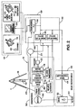
- FIGs. 1 and 2 diagrams of a drawworks control system according to the present invention connected to a drilling rig and including a travelling block is illustrated.
- a system 10 according to the present invention has a derrick 11 that supports, at its upper end, a crown block 15. Suspended by a rope arrangement 17 from the crown block 15 is a travelling block 20, or load bearing part, for supporting a hook structure 25.
- a hoisting line 30 is securely fixed at one end to ground by means of a dead line 35 and a dead line anchor 40.
- the other end of the hoisting line 30 forms a fast line 45 attached to drawworks 50.
- the drawworks 50 includes one or more electrical motors 55 and a transmission 60 connected to a cylindrical rotatable drum 65 for wrapping and unwrapping the fast line 45 as required for operation of the associated crown block 15 and travelling block 20.
- the rotatable drum 65 is also referred to as a winding drum or a hoisting drum.
- a brake arrangement 70 includes a primary friction brake 80, typically a band type brake or disk brake, an auxiliary brake 75, such as an eddy current type brake or a magnetic brake, and an emergency brake 78.
- the brake arrangement 70 is connected to the drawworks 50 by driveshaft 85 of the drawworks 50.
- the brake arrangement 70 is typically actuated either hydraulically or pneumatically, using, for example, a pneumatic cylinder that is engaged by rig air pressure by way of an electronically actuated air valve.
- a load sensing device such as a strain gauge 89 is affixed to the dead line 35, and produces an electrical signal on output line 95 representative of the tension in dead line 35 and consequently, the load carried by travelling block 20.
- Various tension measuring devices may be employed to indicate the tension conditions on the line 30. The actual hook load is calculated using the strain gauge 90 input in conjunction with the number of lines strung and a calibration factor.
- a conventional load cell, hydraulic tension transducers or other load measuring device may be associated with derrick 10 to provide an electrical output load signal representative of the load carried by travelling block 20.
- a measuring device such as an encoder 22, for example, is affixed to the driveshaft 85.
- An electrical output signal representative of the rotation of the rotatable drum 65 is produced on line 24 from encoder 22 as drum 65 rotates to pay out or wind up fast line 45 as the travelling block 20 descends or rises.
- the frequency of the encoder is used to measure the velocity of the travelling block 20 movement, typically, by calculating the actual drum 65 speed and ultimately the travelling block 20 speed based on lines strung, the diameter of the drum 65, the number of line wraps and the line size.
- the velocity of the travelling block 20 movement is calculated from the change in the vertical position of the travelling block 20.
- a plurality of positioning sensors such as proximity switches 26, are used to determine the position of the travelling block 20.
- An electrical output signal from the proximity switches 26 representative of the position of the travelling block 20 will be produced on line 28 and the actual position of the travelling block 20 is calculated based on the drum 65 diameter, the line 30 size and number of lines, the line stretch, and the weight on bit (WOB) which effects line stretch.
- WOB weight on bit
- a drawworks control system 42 receives electrical output signals from the proximity switches 26, the encoder 22 and the strain gauge 89, and is connected to the brake arrangement 70.
- the drawworks control system 42 is connected to a driller or operator control centre 44 located on or near the derrick 11.
- the drawworks control system 42 is also connected to the electrical motor 55 through a drive 46.
- the drawworks motor 55 is an alternating current (AC) motor or a direct current (DC) motor and the drive 46 is an AC or a DC drive respectively.
- the drive 46 for example, includes a controller 48, such as a programmable logic controller (PLC) and one or more power electronic switches 52 connected to an AC bus 54.
- PLC programmable logic controller
- the drive for a DC motor includes an electronic switch 52 such as a silicon controlled rectifier for AC/DC conversion.
- the drawworks control system 42 can include a programmable logic controller (the drawworks PLC 156) and is interfaced with the drive 46 using, for example, a serial communication connection 58 such as, for example, an optical linkage and/or hard wired linkage.
- a serial communication connection 58 such as, for example, an optical linkage and/or hard wired linkage.
- Two or more remote programmable logic controller (PLC) input/output (I/O) units 62 are used to control the transmission 60 and brake arrangement 70 of the drawworks 50.
- PLC remote programmable logic controller
- I/O input/output
- a processor 64 is also connected to the drawworks control system 53 for providing operating parameters and calculated values during the performance of various drilling rig operations.
- the processor 64 is a conventional signal processor, such as a general purpose digital computer.
- the drawworks control system 42 provides a velocity command and a torque command signal to the drive controller 46.
- the drive 46 uses regeneration when necessary to maintain the velocity considering power system limit requirements.
- Each drive 46 provides the motor velocity (with a signed integer to indicate the direction of movement) and the torque level (with a signed integer to indicate the direction of movement) feedback to the drawworks control system 42.
- the drive controller 48 also provides flags to the drawworks control system 42 to indicate various alarm conditions of the drive 46 and the motor 55.
- An operator control centre 44 or man machine interface is, in certain aspects, a console including throttle control joysticks, switches, and an industrial processor driven monitor 69 wherein the operator or driller can set and control certain operational parameters.
- the operator controls the direction and velocity of the travelling block 20 movement using a movement control joystick 71 installed at the operator console.
- the travel of the movement control joystick 71 produces a linear analogue electrical input signal provided to the drawworks PLC 56 of the drawworks control system 42.
- an auxiliary apparatus is used to control the friction brake 80 directly as a backup to the drawworks control system 42, alternatively, bypassing the drawworks control system 42.
- a brake control joystick 76 provides an auxiliary means to directly control the application of the disk brake 80 when necessary.
- the operator selects operational parameters, such as, for example, a gear selection switch 83, an override switch 85 and an emergency shutoff switch 87.
- the monitor is, for example, a typical industrial computer including a touch screen monitor mounted in front of the operator as a part of the man machine interface.
- the operator monitors and sets system parameters and operational parameters including; the number of active drives, the active gear selected, the travelling block position, the block speed, the hook load, the upper and lower position set points, the maximum travelling block velocity set point, the percentage of control disk brake applied, the parked condition, and any abnormal or alarm condition flags or messages.
- the operator can modify the upper and lower travelling block position set points, the maximum travelling block velocity set points and acknowledge certain alarms.
- the operator For hoisting the travelling block 20, the operator, for example, sets the movement control joystick in the hoisting position and the travelling block 20 and any associated equipment or suspended load accelerates upward until the travelling block reaches and maintains the velocity set by the position of the joystick set by the operator.
- the operator For lowering the travelling block 20, the operator, for example, sets the movement control joystick in the lowering position and the travelling block 20 and any associated equipment or suspended load accelerates downward (driven by the electrical motor 55, if required) to reach and maintain the velocity set by the position of the movement control joystick.
- the motors 55 associated with the drawworks 50 are activated to wind fast line 45 onto rotatable drum 65.
- electrical motors 55 are disengaged and rotatable drum 65 is rotated so as to pay out the fast line 45 under the slowing effect of auxiliary brake 75.
- the braking action of the brake arrangement 70 is reduced or de energized completely.
- the braking action of brake 75 is increasingly energized.
- the primary friction brake 80 may be operated by a primary brake operating lever.
- regenerative or dynamic braking of the one or more electric motors 55, controlled by the drive 46 can be used as the primary method of braking during all modes of movement and velocity control, and stopping of the travelling block 20.
- the drawworks control system 42 provides a velocity command signal to the drive 46 for hoisting, lowering and stopping, and the drive 46 maintains the velocity according to the velocity command signal provided using regeneration or dynamic braking when necessary.
- the friction brake 80 is used to back up or compliment this retarding force of regeneration and to hold the travelling block 20 and load in the parking mode.
- Power produced by the brake arrangement 70 provides electrical power to run a motor 90.
- the motor 90 is an electrically-powered high-speed motor.
- magnets used in the motor 90 are not glued in place but are embedded in the motor's rotor.
- the high-speed motor 90 can be used to run rig apparatuses and devices, e.g. the drawworks motors, and items AA, BB, and CC, shown schematically (indicated by dash-dot lines) which may be, but are not limited to, pumps motors, rotaries, top drives, racking systems, and HPU's.
- rig apparatuses and devices e.g. the drawworks motors, and items AA, BB, and CC, shown schematically (indicated by dash-dot lines) which may be, but are not limited to, pumps motors, rotaries, top drives, racking systems, and HPU's.
- the motor 90 runs a generator (or generators) G that produces electrical power.
- This power can be used anywhere on the rig. For example, this power can be used to condition or "clean" power supplied by rig generators T.
- the motor 90 (or the motor-90-generator-G combination) is continuously operational so that its power is available on demand in a critical or emergency situation.
- a system according to the present invention has a drilling rig 41 depicted schematically as a land rig, but other rigs (e.g., offshore rigs and platforms, jack up rigs, semi-submersibles, drill ships, and the like) are within the scope of the present invention.
- a control system 360 controls operations of the rig.
- the rig 411 includes a derrick 413 that is supported on the ground above a rig floor 415.
- the rig 411 includes lifting apparatus, a crown block 417 mounted to derrick 413 and a travelling block 419 interconnected by a cable 421 that is driven by a drawworks 423 (with an electrically powered motor or motors) to control the upward and downward movement of the travelling block 419.
- Travelling block 419 carries a hook 425 from which is suspended a top drive system 427 which includes a variable frequency drive controller 426, a motor (or motors) 424, electrically powered, and a drive shaft 429.
- a power swivel may be used instead of a top drive.
- the top drive system 427 rotates a drillstring 431 to which the drive shaft 429 is connected in a wellbore 433.
- the top drive system 427 can be operated to rotate the drillstring 431 in either direction.
- the drillstring 431 is coupled to the top drive system 427 through an instrumented sub 439 which includes sensors that provide drilling parameter information.
- the drillstring 431 may be any typical drillstring and, in one aspect, includes a plurality of interconnected sections of drill pipe 435 a bottom hole assembly (BHA) 437, which can include stabilizers, drill collars, and/or an apparatus or device, in one aspect, a suite of measurement while drilling (MWD) instruments including a steering tool 451 to provide bit face angle information.
- BHA bottom hole assembly
- MWD measurement while drilling
- a bent sub 441 is used with a downhole or mud motor 442 and a bit 456, connected to the BHA 437.
- the face angle of the bit 456 can be controlled in azimuth and pitch during drilling.
- Drilling fluid is delivered to the drillstring 431 by mud pumps 443 which have electrically-powered motors through a mud hose 445.
- the drillstring 431 is rotated within bore hole 433 by the top drive system 427.
- the drillstring 431 is held in place by top drive system 427 while the bit 456 is rotated by the mud motor 142, which is supplied with drilling fluid by the mud pumps 443.
- the driller can operate top drive system 427 to change the face angle of the bit 456.
- the cuttings produced as the bit drills into the earth are carried out of bore hole 433 by drilling mud supplied by the mud pumps 443.
- Rig utilities are shown collectively and schematically as the block 465.
- a power system 470 with generators 472 (and associated rectifiers as needed) provides power to the various power-consuming items on the rig (as shown by dotted lines).
- Each of the items 423, 427, 443 and 460 has its own single board computer 423c, 427c, 443c and 460c respectively.
- a top drive rig is illustrated, it is, optionally, within the scope of the present invention, for the present invention to be used in connection with a rotary system 460 in which a rotary table and kelly are used to rotate the drillstring (or with a rotary system above).
- the single board computers 423c, 427c, 443c and 460c each have programmable media programmed so that each separate computer calculates a power limit for its particular tool or system.
- a "power limit” is the maximum power consumption for that tool or system (in one particular aspect, a maximum beyond which the tool or system will shut down).
- the computer is programmed to perform the power limit calculations.
- Each single board computer controls its respective tool or system.
- a main control system is in communication with each single board computer.
- each single board computer is programmed to calculate a power limit for its particular tool or system without taking into account the power usage or power requirements of any other power-consuming entity.
- each single tool and system attempts to account for and deal with a total system power deficit or reduction.
- blackouts will not occur since each tool or system will automatically reduce its own power consumption when there is a power deficit or power reduction.
- each tool's and each system's single board computer almost instantaneously takes into account the reduction in available power in setting its own power limit and reduces its power limit accordingly.
- Each single board computer is also programmed to then reduce its tool's power consumption to a level at or below the newly-calculated power limit.
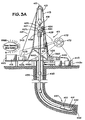
- the system of Fig. 3A has a power recovery motor system PRMS according to the present invention which is any system according to the present invention with a motor or motors for recovering power generated by an apparatus or machine on the rig.
- a power recovery motor system PRMS according to the present invention which is any system according to the present invention with a motor or motors for recovering power generated by an apparatus or machine on the rig.
- Fig. 3B illustrates a system 100 according to the present invention in which a motor M is used to raise and lower a load L in a rig R. Power is supplied to the motor M from a utility input U (e.g. one or more power generators on the rig or a local utility).
- a utility input U e.g. one or more power generators on the rig or a local utility.
- the descent of the load L turns the motor's shaft and thereby the motor generates electricity.
- This generated electricity is transmitted to a high speed motor HSM (e.g., but not limited to, via the utility input) or is transmitted directly from the motor M to the high speed motor HSM.
- the shaft of the high speed motor HSM is then rotated at a high speed, e.g. 7200 rpm, and this rotative power is then available to run another apparatus.
- the power will be available while the shaft of the high speed motor HSM is rotating. In one aspect it might take such a shaft a number of minutes, N, to cease rotation and, for N minutes, the rotative power is available. In one particular aspect N is about 45 minutes.
- the load can be re-raised by the high speed motor HSM which has been previously powered by the electrical power produced by the lowering of a load.
- Fig. 4 shows an offshore platform OP which has a power system with a plurality of generator systems that produce electrical power for a variety of tools and systems.
- Each tool or system has its own single board computer which monitors total power available from the power system and which computes and implements a power limit for its respective tool or system with a method according to the present invention.
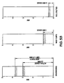
- Figs. 5A - 5C show an adaptive allocation of power according to the present invention to several power consuming entities on a rig at initial power levels and when the total available power decreases.
- Fig. 5A illustrates graphically a power limit and actual power usage for a drawworks, mud pumps, and rig utilities. In this situation there are five generators, each able to produce 1 Megawatt of power. A static power allocation for the rig utilities is assumed to be 500 kilowatts. 1 Megawatt is being used by the mud pumps. The drawworks is, initially, using 2.5 Megawatts.
- a single board computer on the drawworks knows that: there are five generators on line with a total capacity of 5 Megawatts (maximum possible output); the drawworks is presently using 2.5 Megawatts; and that, e.g., at present only 4 Megawatts of power are actually being generated by the five generators. Thus the single board computer calculates that there is 1 spare Megawatt of power.
- the single board computer has calculated a power limit for the drawworks of 3.25 Megawatts. (2.5 MW being used + power preference factor x 1 MW available) "Power preference factor" is a preselected number used to establish priority for power among different tools and systems - each one with its own power preference factor and their total can be less than, equal to, or greater than 1). Assuming a power preference factor of 0.75, the power limit of 3.25 MW is established. In ongoing operations that follow, the single board computer sees an actual usage of 3.0 Megawatts (see Fig. 5B ) and then calculates a power limit for the drawworks of 3.75 Megawatts.
- a drilling rig has a Drawworks, a Top Drive System, a Mud Pump System with multiple Mud Pumps, and three generators.
- the drawworks has three 1150 horsepower motors
- the Top Drive has one 1150 horsepower motor
- the Mud Pump has two 1150 horsepower motors - all motors electrically powered.
- Each generator can produce one Megawatt (MW) of power, so, with all generators running, a maximum of 3 MW of power are available.
- power limits are as follows. TABLE II total capacity current output available capacity Gen 1 1000 700 300 Gen 2 0 0 0 Gen 3 0 0 0 Total 1000 700 300 (capacities in kilowatts) tool limit (HP) tool limit (KW) current output sys power limit calculation power limit used Drawworks 3450 2573 300 600 600 Top Drive 1150 858 300 600 600 Mud Pumps 2300 1715 100 400 400 Total 6900 5145 700 1600 1600
- power limit calculations for the first example described above would be: TABLE III total capacity current output available capacity Gen 1 1000 300 700 Gen 2 1000 300 700 Gen 3 1000 300 700 Total 3000 900 2100 (capacities in kilowatts) tool limit (HP) tool limit (kW) current output pref factor sys power limit calculation power limit used Drawworks 3450 2573 300 50 1350 1350 Top Drive 1150 858 300 60 1560 858 Mud Pumps 2300 1715 100 90 1990 1715 Total 6900 5145 700 200 4900 3923 ("pref factor" is power preference factor)
- the preferred power factors total 100 and the total power limit used by all tools would never exceed the total capacity of the system. In situations in which this is unnecessarily restrictive as seen in the example below, the total power available is 3 MW but the allocated capacity is only 2.7 MW, and thus the total of the power preference factors can, according to the present invention, as desired exceed 100%.
- each tool is able to ultimately use all power available to the system up to its tool limit, but the power allocation would be asymptotic instead of immediate.
- the first two examples are equivalent to having a 100% power preference factor for each tool.
- a digital filter is added to ramp increases in the power limit used per tool and to allow
- the tool's single board computer includes a pre-programmed minimum power limit.
- each tool calculates the actual power usage by each of the other tools (and itself), and allocates the remaining power budget accordingly. This provides a response to any change in the power condition perfectly, but each tool must be reading information, e.g. speed/torque feedbacks, from every tool system, and apparatus on the network. Once each tool has established its power limit, it safely sets the internal speed and torque limits of its motor to operate within the power limit and remain safe. For tools with electrically powered motors, each tool calculates a speed and torque limit based on its static logic and operator requests. The tool's single board computer's software handles the case where the drive is not moving as fast as requested, a result of power limiting.
- ⁇ L ⁇ ⁇ P L / ⁇
- the lesser of the torque limit or the tool supplied torque limit is used.
- such a torque limit is safe to apply since it will never cause a loss of load.
- the power limit is suddenly reduced to 500 kW for the Drawworks.
- each tool controller monitors each generators total current and power individually. It is not an analogue control in the sense of traditional proportional/integral/derivative controls. There are no PID loops in this control.
- An iterative torque limit value is calculated and applied to reduce speed to reduce power.
- a new torque limit value is calculated and applied every controller cycle (e.g. 50 controller cycles per second).
- the controller takes a snap-shot of the tools actual speed and consumer power is being reduced.
- This "locked downward ratcheted speed reference” occurs very fast in a quasi-hyperbolic fashion while approaching the available-power/consumed-power equilibrium asymptote.
- the locked ratcheted speed reference is applied to the drive when the power equation is satisfied.
- systems as in Figs. 3 and 4 may have a power recovery motor system PRMS (which may be any system according to the present invention with a motor or motors for recovering power generated by rig machines and apparatuses and, in certain aspects, then re-using this power).
- PRMS power recovery motor system
- the power recovery motor systems PRMS may be connected to suitable control systems (e.g. a control system CS A ( Fig. 4 ) and/or to a main control system ( Fig. 4 ) and to control systems and/or single board computers on each utilities machine and apparatus (e.g. control system CS A, Fig. 4 and/or individual single board computer or computers, Fig. 4 ). Via lines L the main control system may be in communication with any item, etc. and/or with any other control system and/or computer. Also, e.g., a PRMS system, e.g., via lines N, may be so connected and in communication.
- the power recovery system may provide power to any item, machine, device, utility and/or apparatus on or under a rig.
- embodiments of the present invention use a motor as a flywheel apparatus.
- an "inside out" AC permanent magnet motor rotor acts as the flywheel (or multiple motors are used).
- a motor is a motor 900 as shown in Fig. 9 , with a rotor/flywheel 903 which is a hollow cylinder constructed, e.g. of steel or aluminium, with permanent magnets 904, e.g. rare earth magnets, attached to the inner surface.
- a stator 905 is concentrically located within the rotor, fixed to a stationary hollow shaft 902, so that the rotor revolves around the stator/shaft assembly on roller bearings 901.
- 3-phase cables 907 and optional cooling channels 908 are brought out through the stationary shaft.
- Speed feedback is externally provided to a Variable Frequency Drive (“VFD”) via an absolute position encoder 906.
- VFD provides power back to the motor 900 and can exchange power with a power source "PS” (utility, batteries, and/or generators).
- PS power source
- motors as disclosed in U.S. Application Serial No. 11/789,040 filed 04/23/2007 and U.S. Application Serial No. 11/709,940 filed 02/22/2007 (both co-owned with the present invention and incorporated fully herein for all purposes) may be used.
- the motor may be a motor with: a motor shaft; a plurality of power cables for providing electrical power to the motor; a portion of each of the plurality of power cables passing through the shaft; and a plurality of channels passing through the shaft adjacent the power cables and spaced-apart therefrom, the channels for the passage therethrough of a heat exchange fluid for the exchange of heat with the power cables to cool the power cables.
- the motor may be a permanent magnet motor in which the rotor is made by a method including: preparing a rotor body for emplacement of magnets thereon; the rotor body having a first end spaced-apart from a second end; the rotor body having a generally cylindrical shape with an interior surface and an exterior surface; the rotor body made of magnetic material; applying a plurality of magnets to the interior surface of the rotor body, the magnets held to the rotor body by magnetic force; and emplacing a shunt structure over the plurality of magnets to inhibit inter-magnet action.
- a modular flywheel/motor is rated at 225 kW continuous, with intermittent rating up to 337 kW for 30 seconds.
- Typical angular velocity of one design is 7200 rpm.
- flywheels In either an AC or DC drilling rig, kinetic energy stored in the flywheel (or flywheels) is used to elevate the block or to assist in elevating the block.
- the flywheel(s) and charging mechanism(s) are dimensioned such that their peak output is equal to or greater than the potential energy of the block.
- multiple flywheels are used in order to coordinate the charging and discharging cycles of the flywheel(s) with the motion of the block and kW demand, but also to insure the mechanical and electrical designs are within the practical limits of a portable system.
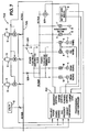
- Fig. 6 shows a system 600 according to the present invention which has a plurality of rig power generators GS each with its own engine E for providing power to run the generators GS. Power from the generators GS runs multiple drawworks D. Optionally a separate utility entity U can supply power to run the generators GS and/or, optionally, such power can be supplied by a battery bank B.
- One, two, three or more flywheel apparatuses F (two shown) store power generated when a load is being lowered by the drawworks D and provide power as needed to run the drawworks D.
- Each flywheel apparatus has a drive components C and V, e.g. a fully regenerative converter and variable frequency inverter which form a complete VFD "variable frequency drive".
- one or more resistor banks R may be used for voltage control, each with a corresponding DC/DC converter or "chopper" T.
- a programmable logic controller PLC (or other suitable control system) controls the system 600.
- charging and discharging of the flywheels F during a braking cycle is managed by the Programmable Logic Controller PLC so that the average power drawn from the generators GS is relatively constant throughout the complete operating phases of the drawworks D.
- Levelling the engine load for the engines E is the job of the PLC.
- the minimum acceptable base load is 70% capacity to insure a minimum standard of efficiency and sufficiently elevated combustion temperatures (e.g. 600 F.) to allow engine emissions controls S to work properly.
- a D.C. Bus MD provides the direct exchange of power between the drawworks motor inverters and the flywheel motor inverters.
- the flywheels F can be charged by using components C and V which consist of fully regenerative converter, variable frequency inverter V, and high speed permanent magnet AC motors F (e.g. but not limited to, as in Fig. 9 ).
- Active IGBT rectifiers can be used as the fully regenerative converter components C to supply both real and reactive power to match the demand of the drawworks motors.
- the flywheels F obtain power from an AC main bus MA through VFD components C and V, and accelerate the flywheels F to a speed whose energy exceeds the potential energy of the block. Storage of energy greater than the potential energy of the drawworks load is preferable in order to overcome losses in the mechanical and electrical systems, and maintain flywheel speeds capable of supporting adequate DC bus voltages.
- the PLC monitors engine output power and available power from all connected sources. It compares these values with block speed and height, and then calculates potential energy of the load. From this information, the PLC manages the charging of the flywheels F and battery banks B (if used). Additionally, exhaust temperatures of the engines E are monitored by the PLC and factored into power management of the flywheels F and batteries of the banks B. Both power absorption and power output of the flywheels F is balanced according to engine exhaust temperatures, engine load, and available power from all connected sources.
- VAR volt amp reactive
- bus frequency and voltage are monitored by sensors O for pre-determined variations. Corrective action is applied by the PLC by injection of real and/or reactive power according to the degree that either bus frequency or voltage deviate from the pre-determined values. Bus frequency feedback along with upward block speed are used by the PLC to determine the rate at which power from the flywheels F is injected onto the main bus M. Silicon controlled rectifier drives, SCR, control output power and speed of the drawworks DC traction motors.
- Fig. 7 shows a system 700 according to the present invention with some parts and components like those of the system 600 (and like parts and components have the same identifiers in Fig. 6 and Fig. 7 ).
- the drive components C in the system of Fig. 6 are not needed in the system of Fig. 7 which uses AC-powered motors for its drawworks K.
- power is exchanged between flywheel inverters N and drawworks inverters W across the DC bus.
- VARs are supplied directly to the AC motors of the drawworks from the drawworks inverters W so VAR injection on an AC bus 702 is not required.
- Systems with a DC drawworks manage both kW and kVAR injection at a main AC bus ( Fig. 6 ).
- control of the flywheels F is based on power demand, available power, and exhaust temperatures of the engines E.
- energy to overcome mechanical losses and drive inefficiencies is supplied from external sources including, but not limited to, the generators GS, utilities U, or battery banks B.
- a rig with three 1000 kW (maximum power output rating) engines E will operate with a base load of 2500 kW. Therefore, each engine E is operating at 83% capacity. Operation of the drawworks K demands an additional 1000 kW intermittently (for example, 30 seconds). Total power demand is 3500 kW while operating the drawworks K. Without an energy storage mechanism such as the flywheels F, an additional engine E is required to run in reserve in order to supply power for the peak load. But with four engines on line, their output can vary from 62.5% capacity to 87.5% capacity, so average engine demand over the range is 75%, although this may not be an accurate average over time. Fuel efficiency is poor and loading is insufficient to reliably operate the installed emissions controls on the engines.
- Exhaust temperatures are maintained by maintaining engine loading at sufficient levels e.g., in certain aspects above 70% of maximum, e.g. by levelling the load with flywheels. Without the flywheels and with four 1000kW engines, the engine loading swings from 62.5% to 87.5%, which violates the 70% minimum load requirement for several minutes during each drawworks "tripping cycle". Using the flywheels in combination with three 1000kW engines, engines are loaded by the flywheels during the minimum demand, and then contribute power during the maximum demand, so the average load on the engines is always above 70%.
- engine exhaust temperature is how power is managed in this utilization of the flywheels.
- the object is to stabilize the power system and recover energy.
- emission levels are maintained within regulations set by the EPA or other regulatory agencies or bodies.
- flywheels and battery banks permits novel modes of operation in well service rigs (also known as "workover rigs").
- Well service rigs employing only a drawworks as a primary consumer of electric power can take advantage of the systems according to the present invention e.g. as shown in Figs. 6 and 7 .
- Such systems can operate entirely on battery power, utility power, or a combination of both.
- the PLC utilizes all available utility power and draws the balance from the battery bank.
- flywheel control is focused on conservation of energy from the drawworks. This means that excess energy is stored in the battery banks, whenever possible.
- the rig generator typically one per rig
- the rig generator is used only to charge depleted batteries, or when loading is such that it is impossible to operate otherwise.
- Fig. 8 shows a system 800 for use in such a way with inverter(s) IR, battery bank(s) BK, and flywheels FW (which may be any inverter, any battery bank, and any flywheel apparatus disclosed herein).
Landscapes
- Engineering & Computer Science (AREA)
- Mechanical Engineering (AREA)
- Chemical & Material Sciences (AREA)
- Combustion & Propulsion (AREA)
- General Engineering & Computer Science (AREA)
- Mining & Mineral Resources (AREA)
- Life Sciences & Earth Sciences (AREA)
- Geology (AREA)
- Fluid Mechanics (AREA)
- Environmental & Geological Engineering (AREA)
- Physics & Mathematics (AREA)
- General Life Sciences & Earth Sciences (AREA)
- Geochemistry & Mineralogy (AREA)
- Control Of Eletrric Generators (AREA)
- Control Of Multiple Motors (AREA)
- Earth Drilling (AREA)
- Control Of Vehicle Engines Or Engines For Specific Uses (AREA)
- Hybrid Electric Vehicles (AREA)
Claims (15)
- Système (600, 700) pour commander une charge de puissance sur un moteur de plate-forme de forage (472) d'une plate-forme de forage de puits, le système comprenant :un organe de commande pour commander ledit moteur de plate-forme de forage (472) ; etun capteur pour mesurer une température de sortie dudit moteur de plate-forme de forage (472), le capteur étant en communication avec l'organe de commande pour délivrer à l'organe de commande des signaux indicatifs de la température de sortie,caractérisé en ce que, en utilisation, ledit organe de commande a pour objectif de maintenir ladite température de sortie sensiblement constante en commandant la charge de puissance placée sur ledit moteur de plate-forme de forage (472), quelle que soit la demande de puissance en cours de la part de ladite plate-forme de forage de puits.
- Système selon la revendication 1, comprenant en outre un appareil de stockage d'énergie pour stocker l'énergie à délivrer à ladite plate-forme de forage de puits lorsque la demande de puissance de la part de ladite plate-forme de forage de puits augmente et/ou pour satisfaire une demande de puissance existante.
- Système selon la revendication 2, dans lequel ledit système est adapté pour stocker dans ledit appareil de stockage d'énergie toute énergie en excès générée par l'appareil à un endroit de ladite plate-forme de forage de puits.
- Système selon la revendication 3, dans lequel ledit système est adapté pour stocker au moins une partie de l'énergie libérée pendant l'abaissement et/ou le freinage d'un palan mobile (2C) par un treuil de manoeuvre (5C) sur ladite plate-forme de forage de puits.
- Système selon la revendication 3 ou 4, dans lequel ledit système est adapté pour libérer une partie de son énergie stockée afin d'aider un treuil de manoeuvre (50) à lever un palan mobile (20) sur ladite plate-forme de forage de puits.
- Système selon la revendication 5, dans lequel un pic de puissance en sortie dudit appareil de stockage d'énergie est au moins sensiblement égal à une énergie potentielle dudit palan mobile (20), et en option dans lequel le pic de puissance est supérieur à ladite énergie potentielle.
- Système selon l'une quelconque des revendications 2 à 6, dans lequel en utilisation toute puissance générée par ledit moteur de plate-forme de forage (472) au-delà de ce qui est requis par ladite plate-forme de forage de puits est stockée dans ledit appareil de stockage d'énergie.
- Système selon l'une quelconque des revendications 2 à 7, dans lequel ledit appareil de stockage d'énergie comprend un appareil à volant, et dans lequel en utilisation ledit organe de commande commande l'appareil à volant, tel qu'un moteur à courant alternatif à l'envers.
- Système selon l'une quelconque des revendications précédentes, comprenant en outre une source de puissance pour fournir de la puissance à ladite plate-forme de forage de puits, et ledit organe de commande gère la puissance disponible provenant de ladite source de puissance, dans lequel ladite source de puissance comprend au moins un parmi : une alimentation en courant électrique, une batterie, un générateur de plate-forme de forage et un appareil à volant, et dans lequel en utilisation l'organe de commande compare des valeurs de puissance disponibles avec une vitesse et une hauteur de palan mobile, et calcule, en se fondant sur cette comparaison, une énergie potentielle dudit palan mobile (20) et commande en conséquence la charge de puissance de tout appareil de stockage d'énergie et/ou de batterie.
- Système selon la revendication 9, dans lequel il y a un appareil à volant et l'organe de commande régule la puissance délivrée à l'appareil à volant avec la puissance fournie par l'appareil à volant en se fondant sur la température de sortie de la plate-forme de forage, toute la puissance disponible, et la charge de puissance souhaitée sur ledit moteur de plate-forme de forage (472).
- Système selon l'une quelconque des revendications précédentes, dans lequel ladite plate-forme de forage comprend une plate-forme de service de puits qui est alimenté en utilisation en puissance par ledit moteur de plate-forme de forage (472), le système comprenant en outre
une source de puissance de type alimentation en courant électrique,
une source de puissance de type générateur de plate-forme de forage,
une source de puissance de type batterie,
un appareil de stockage énergie pour stocker la puissance générée par le fonctionnement d'un système de treuil de manoeuvre de plate-forme de forage (50), eL
ledit organe de commande pour commander la puissance délivrée par ledit moteur de plate-forme de forage. - Système selon la revendication 11, dans lequel en utilisation ledit organe de commande démarre ou arrête ledit générateur de plate-forme de forage afin de charger la source de puissance de type batterie et/ou pour faire fonctionner le treuil de manoeuvre (50).
- Système selon la revendication 11 ou 12, dans lequel ledit organe de commande commande la source de puissance de sorte que ledit système de treuil de manoeuvre fonctionne uniquement avec la puissance fournie par ladite source de puissance de type batterie.
- Système selon l'une quelconque des revendications précédentes, comprenant en outre :des appareils de plate-forme de forage,une pluralité de générateurs de plate-forme de forage pour délivrer de la puissance audit moteur de plate-forme de forage et auxdits appareils de la plate-forme de forage,ledit moteur de plate-forme de forage et chaque appareil de plate-forme de forage possédant chacun une commande d'ordinateur de bord,ledit organe de commande pour gérer la pluralité de générateurs de plate-forme de forage afin de déterminer si un générateur de plate-forme de forage est en panne, etchaque commande d'ordinateur de bord individuelle prenant en compte une réduction de la puissance disponible due une panne d'un générateur de plate-forme de forage et chaque commande d'ordinateur de bord individuelle réduisant une limite de puissance pour son appareil de plate-forme de forage ou moteur de plate-forme de forage correspondant.
- Plate-forme de forage de puits comprenant un système selon l'une quelconque des revendications précédentes.
Applications Claiming Priority (3)
| Application Number | Priority Date | Filing Date | Title |
|---|---|---|---|
| US90272507P | 2007-02-22 | 2007-02-22 | |
| US11/983,214 US20080203734A1 (en) | 2007-02-22 | 2007-11-07 | Wellbore rig generator engine power control |
| PCT/GB2008/050068 WO2008102166A1 (fr) | 2007-02-22 | 2008-02-05 | Commande de moteur d'appareil de forage |
Publications (2)
| Publication Number | Publication Date |
|---|---|
| EP2126268A1 EP2126268A1 (fr) | 2009-12-02 |
| EP2126268B1 true EP2126268B1 (fr) | 2012-02-22 |
Family
ID=39301167
Family Applications (1)
| Application Number | Title | Priority Date | Filing Date |
|---|---|---|---|
| EP20080702151 Active EP2126268B1 (fr) | 2007-02-22 | 2008-02-05 | Commande de moteur d'appareil de forage |
Country Status (6)
| Country | Link |
|---|---|
| US (2) | US20080203734A1 (fr) |
| EP (1) | EP2126268B1 (fr) |
| CN (1) | CN101675206A (fr) |
| AT (1) | ATE546611T1 (fr) |
| CA (1) | CA2678668C (fr) |
| WO (1) | WO2008102166A1 (fr) |
Families Citing this family (99)
| Publication number | Priority date | Publication date | Assignee | Title |
|---|---|---|---|---|
| US7923946B2 (en) * | 2007-05-18 | 2011-04-12 | Williams Kevin R | Flywheel-based energy storage on a heave-compensating drawworks |
| US7633248B1 (en) * | 2007-05-18 | 2009-12-15 | Williams Kevin R | Flywheel-based energy storage on a heave-compensating drawworks |
| US7717193B2 (en) * | 2007-10-23 | 2010-05-18 | Nabors Canada | AC powered service rig |
| US7687950B2 (en) * | 2007-11-27 | 2010-03-30 | Vector Magnetics Llc | Drillstring alternator |
| US20090195074A1 (en) * | 2008-01-31 | 2009-08-06 | Buiel Edward R | Power supply and storage device for improving drilling rig operating efficiency |
| US7573144B1 (en) * | 2008-02-07 | 2009-08-11 | Direct Drive Systems, Inc. | Reconfigurable power system using multiple phase-set electric machines |
| US20090200856A1 (en) * | 2008-02-13 | 2009-08-13 | Chehade Elie J | Methods and systems for raising and lowering a rig mast and substructure by remote control |
| DE102008022618A1 (de) * | 2008-05-07 | 2009-12-31 | Siemens Aktiengesellschaft | Stromversorgungseinrichtung |
| US20090312885A1 (en) * | 2008-06-11 | 2009-12-17 | Buiel Edward R | Management system for drilling rig power supply and storage system |
| EP2356307A4 (fr) | 2008-11-14 | 2016-04-13 | Canrig Drilling Tech Ltd | Systeme de volant d'inertie pour une utilisation avec des roues electriques dans un vehicule hybride |
| US20100329905A1 (en) * | 2008-12-02 | 2010-12-30 | Williams Kevin R | Permanent magnet direct drive mud pump |
| EP2196622A1 (fr) * | 2008-12-12 | 2010-06-16 | Welltec A/S | Module d'intervention de puits sous-marin |
| US20110309315A1 (en) * | 2008-12-22 | 2011-12-22 | Williams Kevin R | Two speed direct drive drawworks |
| US8672059B2 (en) * | 2008-12-22 | 2014-03-18 | Canrig Drilling Technology Ltd. | Permanent magnet direct drive drawworks |
| US20100252325A1 (en) * | 2009-04-02 | 2010-10-07 | National Oilwell Varco | Methods for determining mechanical specific energy for wellbore operations |
| USRE46725E1 (en) | 2009-09-11 | 2018-02-20 | Halliburton Energy Services, Inc. | Electric or natural gas fired small footprint fracturing fluid blending and pumping equipment |
| US9059587B2 (en) | 2009-12-04 | 2015-06-16 | Kevin R. Williams | System and method of supplying power to loads of a drilling rig |
| US9197071B2 (en) | 2009-12-04 | 2015-11-24 | Kevin R. Williams | Energy storage system for supplying power to loads of a drilling rig |
| US9065300B2 (en) | 2009-12-04 | 2015-06-23 | Kevin R. Williams | Dual fuel system and method of supplying power to loads of a drilling rig |
| US8446037B2 (en) * | 2009-12-04 | 2013-05-21 | Kevin R. Williams | Energy storage system for peak-shaving of drilling rig power usage |
| AU2010339868B2 (en) * | 2009-12-21 | 2015-04-23 | Kevin R. Williams | Permanent magnet direct drive drawworks |
| EP2534561B1 (fr) * | 2010-02-10 | 2018-08-08 | Microchip Technology Germany GmbH | Clavier d'ordinateur avec un arrangement d'électrodes |
| CN101806209A (zh) * | 2010-02-26 | 2010-08-18 | 江苏通华电力设备有限公司 | 深孔钻车智能控制装置 |
| DE102010010749B4 (de) * | 2010-03-09 | 2016-12-22 | Wacker Neuson Produktion GmbH & Co. KG | Antriebssystem mit Vorrichtung zur Unterbrechung des Betriebs bei drohendem Betriebsstoffmangel sowie Arbeitsgerät und Verfahren |
| WO2011149478A1 (fr) * | 2010-05-28 | 2011-12-01 | Canrig Drilling Technology Ltd. | Systèmes et procédés de gestion de carburant d'une installation de forage |
| US9385531B2 (en) * | 2010-08-24 | 2016-07-05 | Bennett Hill Branscomb | System and method for optimizing returns of power feedstock producers |
| EP2482425A1 (fr) * | 2011-02-01 | 2012-08-01 | Siemens Aktiengesellschaft | Système de fonctionnement pendant un manque de courant total, |
| EP2503666A3 (fr) * | 2011-02-01 | 2013-04-17 | Siemens Aktiengesellschaft | Système d'alimentation pour commande électrique d'un navire |
| US9140110B2 (en) | 2012-10-05 | 2015-09-22 | Evolution Well Services, Llc | Mobile, modular, electrically powered system for use in fracturing underground formations using liquid petroleum gas |
| US11255173B2 (en) | 2011-04-07 | 2022-02-22 | Typhon Technology Solutions, Llc | Mobile, modular, electrically powered system for use in fracturing underground formations using liquid petroleum gas |
| MX389079B (es) * | 2011-04-07 | 2025-03-20 | Typhon Tech Solutions Llc | Sistema modular móvil eléctricamente accionado para el uso en la fractura de formaciones subterráneas. |
| US11708752B2 (en) | 2011-04-07 | 2023-07-25 | Typhon Technology Solutions (U.S.), Llc | Multiple generator mobile electric powered fracturing system |
| ITVI20110135A1 (it) * | 2011-05-26 | 2012-11-27 | Fade Engineering S A S Di Inverardi Ennio & C | Sistema di controllo movimentazione per impianto di trivellazione |
| US20140048286A1 (en) * | 2011-08-09 | 2014-02-20 | Fabian Fidel Rojas | Systems and methods for a modular drum with a common power pack unit |
| US20140077600A1 (en) * | 2012-09-14 | 2014-03-20 | Robert Douglas Cryer | System and method for controlling energy storage and distribution |
| US10289080B2 (en) | 2012-10-11 | 2019-05-14 | Flexgen Power Systems, Inc. | Multi-generator applications using variable speed and solid state generators for efficiency and frequency stabilization |
| US9312699B2 (en) | 2012-10-11 | 2016-04-12 | Flexgen Power Systems, Inc. | Island grid power supply apparatus and methods using energy storage for transient stabilization |
| US9394770B2 (en) | 2013-01-30 | 2016-07-19 | Ge Oil & Gas Esp, Inc. | Remote power solution |
| US9553517B2 (en) | 2013-03-01 | 2017-01-24 | Fllexgen Power Systems, Inc. | Hybrid energy storage system and methods |
| CN103500387B (zh) * | 2013-07-05 | 2016-04-27 | 山西太钢不锈钢股份有限公司 | 一种天车智能终端和仓储运输管理系统的通讯方法 |
| DE102013214635A1 (de) * | 2013-07-26 | 2015-02-19 | Leonardo Uriona Sepulveda | Antrieb und Verfahren zur Bereitstellung hoher Antriebsdynamik bei hohen Antriebsleistungen bei der Gas- und/oder Ölgewinnung sowie Verwendung eines solchen Antriebs |
| CN106233581A (zh) | 2014-02-03 | 2016-12-14 | 坎里格钻探技术有限公司 | 电动机中永磁体的联接 |
| CA2935772C (fr) * | 2014-02-04 | 2021-08-03 | Canrig Drilling Technology Ltd. | Regulation de la charge d'un generateur |
| WO2015138833A1 (fr) | 2014-03-13 | 2015-09-17 | Canrig Drilling Technology Ltd. | Treuil de forage à entraînement direct à faible inertie |
| US9919903B2 (en) | 2014-03-13 | 2018-03-20 | Nabors Drilling Technologies Usa, Inc. | Multi-speed electric motor |
| CN103944157B (zh) * | 2014-03-27 | 2016-09-14 | 中国科学院电工研究所 | 一种用于钻机的直流供电系统及其控制方法 |
| US9581010B2 (en) * | 2014-04-03 | 2017-02-28 | National Oilwell Varco, L.P. | Modular instrumented shell for a top drive assembly and method of using same |
| US9562405B2 (en) * | 2014-05-11 | 2017-02-07 | William Thomas Carpenter | Method and apparatus for continuous raising and lowering joints of pipe |
| CN105337397B (zh) * | 2014-06-18 | 2019-03-29 | 通用电气公司 | 钻探系统及其供电方法 |
| US10150659B2 (en) | 2014-08-04 | 2018-12-11 | Nabors Drilling Technologies Usa, Inc. | Direct drive drawworks with bearingless motor |
| US9365265B2 (en) * | 2014-10-28 | 2016-06-14 | Electronic Power Design, Inc. | Hybrid winch with controlled release and torque impulse generation control for anchor handling offshore |
| US9644431B2 (en) * | 2014-11-26 | 2017-05-09 | Integrated Drive Systems LLC | Drilling rig system having improved electrical subsystem |
| US10337424B2 (en) * | 2014-12-02 | 2019-07-02 | Electronic Power Design, Inc. | System and method for energy management using linear programming |
| FR3029712B1 (fr) * | 2014-12-03 | 2017-12-15 | Ifp Energies Now | Systeme d'actionnement lineaire electrique equipe de moyens de stockage d'energie |
| EP3241262B1 (fr) | 2014-12-30 | 2020-08-19 | Flexgen Power Systems, Inc. | Dispositif de stabilisation de puissance transitoire à régulation de puissance active et réactive |
| US9634599B2 (en) | 2015-01-05 | 2017-04-25 | Canrig Drilling Technology Ltd. | High speed ratio permanent magnet motor |
| WO2016131460A1 (fr) * | 2015-02-20 | 2016-08-25 | Maersk Drilling A/S | Système de génération et de distribution d'énergie pour unités de forage en mer |
| PL3259821T3 (pl) | 2015-02-20 | 2019-09-30 | Maersk Drilling A/S | System wytwarzania i dystrybucji mocy dla morskich jednostek wiertniczych |
| CN108025806A (zh) * | 2015-07-13 | 2018-05-11 | 恩斯科国际公司 | 浮动结构 |
| US10283966B2 (en) | 2015-07-31 | 2019-05-07 | Bluvert Technologies Ltd. | System and methods for power generation |
| EP3362635A1 (fr) * | 2015-10-12 | 2018-08-22 | Itrec B.V. | Entretien d'un dispositif de tête d'injection motorisée d'une installation de forage de puits |
| JP6675259B2 (ja) * | 2016-04-20 | 2020-04-01 | 株式会社マキタ | 電動作業機 |
| US10146242B2 (en) | 2016-08-25 | 2018-12-04 | Caterpillar Inc. | Micro grid power system |
| CA3206994A1 (fr) | 2016-09-02 | 2018-03-08 | Halliburton Energy Services, Inc. | Systemes de motorisation hybride pour operations de stimulation de puits |
| US10491004B2 (en) * | 2016-10-19 | 2019-11-26 | Caterpillar Inc. | Systems and methods for controlling power output to a load by multiple gensets based on load operation modes |
| SG10201609106XA (en) * | 2016-10-31 | 2018-05-30 | Keppel Offshore & Marine Tech Ct Pte Ltd | Power storage and supply method and system for a drilling rig |
| US9856719B1 (en) * | 2016-12-21 | 2018-01-02 | Kevin R. Williams | System for supplying power from the main powerhouse to a drill floor powerhouse |
| US12442338B2 (en) | 2017-01-25 | 2025-10-14 | Electronic Power Design, Inc. | Mobile electric fracking trailer power supply system |
| WO2018201118A1 (fr) * | 2017-04-28 | 2018-11-01 | Schlumberger Technology Corporation | Unité d'alimentation et d'électronique intégrée pour machine de forage |
| US11008834B2 (en) | 2017-05-01 | 2021-05-18 | Schlumberger Technology Corporation | Integrated drilling rig machine |
| CA2967921A1 (fr) | 2017-05-23 | 2018-11-23 | Rouse Industries Inc. | Gestion d'alimentation electrique d'un appareil de forage |
| US20180355682A1 (en) * | 2017-06-13 | 2018-12-13 | Schlumberger Technology Corporation | Oil Field Services Apparatus and Methods |
| JP7108874B2 (ja) * | 2017-07-26 | 2022-07-29 | パナソニックIpマネジメント株式会社 | 電源監視データ処理装置、電源監視データ処理方法、および電源監視データ処理プログラム |
| US11322942B2 (en) * | 2017-10-12 | 2022-05-03 | Schlumberger Technology Corporation | Electrical power generation and distribution system with power recovery and regeneration |
| US11050377B2 (en) | 2017-10-30 | 2021-06-29 | Schlumberger Technology Corporation | Systems and methods for managing drive parameters after maintenance |
| US10920562B2 (en) | 2017-11-01 | 2021-02-16 | Schlumberger Technology Corporation | Remote control and monitoring of engine control system |
| CN107748536A (zh) * | 2017-11-23 | 2018-03-02 | 威海人合机电股份有限公司 | 一种油田试井车电驱系统 |
| WO2019118352A1 (fr) | 2017-12-11 | 2019-06-20 | Schlumberger Technology Corporation | Entraînement à fréquence variable refroidi par air |
| US11264801B2 (en) * | 2018-02-23 | 2022-03-01 | Schlumberger Technology Corporation | Load management algorithm for optimizing engine efficiency |
| US12176738B1 (en) * | 2018-03-01 | 2024-12-24 | Paul F. Rembach | System for recovering inertial energy |
| IT201800003793A1 (it) * | 2018-03-20 | 2019-09-20 | Soilmec Spa | Macchina perforatrice dotata di un dispositivo di movimentazione della batteria di perforazione a frenata elettrica. |
| WO2019232515A1 (fr) * | 2018-06-01 | 2019-12-05 | Schlumberger Technology Corporation | Système de gestion d'énergie d'appareil de forage |
| CN109695419A (zh) * | 2018-11-28 | 2019-04-30 | 中国石油集团渤海石油装备制造有限公司 | 一种机械钻机井架安全起升装置 |
| CN109458132B (zh) * | 2018-11-30 | 2023-08-18 | 石家庄博安煤矿机械制造有限公司 | 一种钻车及其控制系统 |
| US12286204B2 (en) * | 2019-07-01 | 2025-04-29 | Electronic Power Design, Inc. | Hybrid power generation plant system and method |
| US11180964B2 (en) * | 2019-08-20 | 2021-11-23 | Barry J. Nield | Interlock for a drill rig and method for operating a drill rig |
| NO345864B1 (en) * | 2019-09-02 | 2021-09-13 | Odfjell Drilling As | An energy system for a Mobile Offshore Drilling Unit (MODU), a MODU and a method of supplying power to the MODU |
| US11920438B2 (en) | 2019-10-17 | 2024-03-05 | Schlumberger Technology Corporation | Intelligent power management system |
| CN112031739B (zh) * | 2020-08-27 | 2021-08-24 | 江苏辰午节能科技股份有限公司 | 一种用于石油钻井的双电机驱动系统及其控制方法 |
| WO2022104330A1 (fr) | 2020-11-10 | 2022-05-19 | Helmerich & Payne Technologies, Llc | Systèmes et techniques de gestion de puissance |
| CN113879998B (zh) * | 2021-10-20 | 2023-03-10 | 天水电气传动研究所集团有限公司 | 一种石油钻机绞车断轴保护方法 |
| US12573845B2 (en) | 2022-08-17 | 2026-03-10 | Nabors Drilling Technologies Usa, Inc. | Power management with an energy storage system |
| CN115341888B (zh) * | 2022-09-02 | 2025-03-18 | 上海中联重科桩工机械有限公司 | 用于旋挖钻机的控制方法、装置、旋挖钻机及存储介质 |
| US11955782B1 (en) | 2022-11-01 | 2024-04-09 | Typhon Technology Solutions (U.S.), Llc | System and method for fracturing of underground formations using electric grid power |
| CN115853648B (zh) * | 2022-12-13 | 2025-10-31 | 吉林大学 | 一种多变量耦合的旋挖钻机油门控制方法及系统 |
| WO2024205591A1 (fr) * | 2023-03-30 | 2024-10-03 | Halliburton Energy Services, Inc. | Prolongement de la durée de vie de batteries rechargeables de fond de trou |
| US12215573B2 (en) * | 2023-04-26 | 2025-02-04 | Patterson-Uti Drilling Company Llc | Method and system for stealth mode operation of a drilling rig |
| US12540607B2 (en) | 2023-06-23 | 2026-02-03 | Halliburton Energy Services, Inc. | Hybrid drive and distributed power systems for well stimulation operations |
| IT202300014637A1 (it) * | 2023-07-12 | 2025-01-12 | Systemitalia S R L | Sistema per il collaudo contemporaneo di tutte le macchine critiche operanti sugli impianti di perforazione petrolifera |
Family Cites Families (70)
| Publication number | Priority date | Publication date | Assignee | Title |
|---|---|---|---|---|
| US1983260A (en) * | 1929-04-15 | 1934-12-04 | Zorzi Carlo | Combined motor and compressor |
| US1875763A (en) * | 1930-06-30 | 1932-09-06 | Ideal Electric & Mfg Co | Compound synchronous motor |
| US1983262A (en) * | 1931-03-07 | 1934-12-04 | Zorzi Cario | Combined motor and compressor |
| US2261670A (en) * | 1935-04-08 | 1941-11-04 | Thermal Engineering Company | Control means for internal combustion engines |
| US2301943A (en) * | 1937-07-28 | 1942-11-17 | Georg Otto | Working machine with flywheel of variable inertia moment |
| US2261671A (en) * | 1940-08-03 | 1941-11-04 | Thermal Engineering Company | Control means |
| US2383103A (en) * | 1943-03-09 | 1945-08-21 | Singer Mfg Co | Electric power transmitter |
| US2461504A (en) * | 1947-11-03 | 1949-02-08 | Singer Mfg Co | Electric transmitter for driving sewing machines and the like |
| US2857534A (en) * | 1954-07-06 | 1958-10-21 | Sperry Rand Corp | Combination electric motor and gyroscopic structures |
| US2812461A (en) * | 1956-03-20 | 1957-11-05 | Meier-Maletz Max | Drive for small machinery, alternatively to be used for electric and mechanical energy |
| GB976279A (en) * | 1962-09-26 | 1964-11-25 | Socony Mobil Oil Co Inc | Gas-powered drilling rig |
| US3324717A (en) * | 1963-10-28 | 1967-06-13 | Mobil Oil Corp | System and method for optimizing drilling operations |
| JPS4521047B1 (fr) * | 1967-09-26 | 1970-07-17 | ||
| US3538363A (en) * | 1968-09-26 | 1970-11-03 | David Isaakovich Maryanovsky | Electric drive to be employed in a drilling rig |
| JPS5938422B2 (ja) * | 1971-10-15 | 1984-09-17 | ウエスチングハウス・エレクトリツク・コーポレーシヨン | ガスタ−ビン式パワ−・プラント |
| GB1359390A (en) * | 1971-12-28 | 1974-07-10 | Nippon Steel Corp | Screw press |
| US3894244A (en) * | 1973-10-03 | 1975-07-08 | Ross K Hill | Power limit and control system |
| US4171029A (en) * | 1974-05-10 | 1979-10-16 | U.S. Philips Corporation | Vehicle propulsion system with inertial storage |
| US4057736A (en) * | 1974-09-13 | 1977-11-08 | Jeppson Morris R | Electrical power generation and distribution system |
| US3983738A (en) * | 1974-11-13 | 1976-10-05 | Viktor Ivanovich Vlasov | Crank press drive |
| US4097752A (en) * | 1975-07-12 | 1978-06-27 | Daimler-Benz Aktiengesellschaft | Power supply of installations driven by internal combustion engines, especially of motor vehicles |
| US4187546A (en) * | 1977-03-15 | 1980-02-05 | B. J. Hughes Inc. | Computer-controlled oil drilling rig having drawworks motor and brake control arrangement |
| US4136286A (en) * | 1977-07-05 | 1979-01-23 | Woodward Governor Company | Isolated electrical power generation system with multiple isochronous, load-sharing engine-generator units |
| US4376250A (en) * | 1979-12-26 | 1983-03-08 | Dynamote Corporation | Portable power source |
| US4322630A (en) * | 1980-03-17 | 1982-03-30 | Gould Inc. | Electrical power generating system |
| US4353024A (en) * | 1980-06-10 | 1982-10-05 | Westinghouse Electric Corp. | Control for VAR generator with deadband |
| US4590416A (en) * | 1983-08-08 | 1986-05-20 | Rig Efficiency, Inc. | Closed loop power factor control for power supply systems |
| US4482857A (en) * | 1983-08-08 | 1984-11-13 | Rig Efficiency, Inc. | Closed loop power factor control for drilling rigs |
| US4686375A (en) * | 1986-03-05 | 1987-08-11 | Power Group International Corp. | Uninterruptible power supply cogeneration system |
| US4724672A (en) * | 1986-06-23 | 1988-02-16 | Olmsted Peter B | Energy storing hydraulic lift pump for oil wells |
| US5050936A (en) * | 1988-10-27 | 1991-09-24 | Isuzu Motors Limited | Regenerative braking system for car |
| US5066866A (en) * | 1989-12-26 | 1991-11-19 | Hallidy William M | Power converter system |
| CA2085044C (fr) * | 1992-12-10 | 2000-03-28 | Gu Xinyi | Systeme de levage de l'appareil de forage d'un puits et systeme de levage de l'appareil de forage emmagasinant l'energie hydraulique |
| GB9306136D0 (en) * | 1993-03-24 | 1993-05-12 | Plessey Telecomm | Opto-electronic circuits |
| US5422517A (en) * | 1993-05-26 | 1995-06-06 | United Technologies Corporation | Control of electric loads during generator failure in a multi-generator system |
| GB9318591D0 (en) * | 1993-09-08 | 1993-10-27 | Ellis Christopher W H | Kinetic energy storage system |
| BR9408005A (pt) * | 1993-11-08 | 1996-12-03 | Rosen Motors Lp | Sistema de volante para armazenagem móvel de energia |
| US5513728A (en) * | 1994-04-19 | 1996-05-07 | Reliance Electric Industrial Company | Brake system for mining conveyor |
| US5566091A (en) * | 1994-06-30 | 1996-10-15 | Caterpillar Inc. | Method and apparatus for machine health inference by comparing two like loaded components |
| US5724242A (en) * | 1995-03-21 | 1998-03-03 | Caterpillar Inc. | Method for producing production control software for a natural gas engine controller |
| US5734255A (en) * | 1996-03-13 | 1998-03-31 | Alaska Power Systems Inc. | Control system and circuits for distributed electrical power generating stations |
| US5746278A (en) * | 1996-03-13 | 1998-05-05 | Vermeer Manufacturing Company | Apparatus and method for controlling an underground boring machine |
| US5929538A (en) * | 1997-06-27 | 1999-07-27 | Abacus Controls Inc. | Multimode power processor |
| JP3454101B2 (ja) * | 1997-09-05 | 2003-10-06 | 日産自動車株式会社 | 電気自動車の発電制御装置 |
| US6166525A (en) * | 1998-01-26 | 2000-12-26 | Crook; Gaines M. | Automatic electric power generator control |
| US6000479A (en) * | 1998-01-27 | 1999-12-14 | Western Atlas International, Inc. | Slimhole drill system |
| FR2775018B1 (fr) * | 1998-02-13 | 2000-03-24 | Elf Exploration Prod | Methode de conduite d'un puits de production d'huile et de gaz active par un systeme de pompage |
| US6958550B2 (en) * | 1998-04-02 | 2005-10-25 | Capstone Turbine Corporation | Method and system for control of turbogenerator power and temperature |
| US6029951A (en) * | 1998-07-24 | 2000-02-29 | Varco International, Inc. | Control system for drawworks operations |
| US6169334B1 (en) * | 1998-10-27 | 2001-01-02 | Capstone Turbine Corporation | Command and control system and method for multiple turbogenerators |
| US6198176B1 (en) * | 1999-02-16 | 2001-03-06 | Statordyne Llc | UPS/CPS system |
| US6161495A (en) * | 1999-04-01 | 2000-12-19 | Western Atlas International, Inc | Power storage for marine seismic vessel |
| US6599095B1 (en) * | 1999-04-28 | 2003-07-29 | Kabushiki Kaisha Yaskawa Denki | Pump-off control method of pump jack |
| US6250080B1 (en) * | 1999-06-24 | 2001-06-26 | Wartsila Nsd North America, Inc. | Mobile modular intermodal cogeneration system |
| WO2001051760A2 (fr) * | 2000-01-12 | 2001-07-19 | The Charles Machine Works, Inc. | Systeme destine a automatiquement percer et aleser des trous de sonde |
| US6315523B1 (en) * | 2000-02-18 | 2001-11-13 | Djax Corporation | Electrically isolated pump-off controller |
| US7218244B2 (en) * | 2001-09-25 | 2007-05-15 | Vermeer Manufacturing Company | Common interface architecture for horizontal directional drilling machines and walk-over guidance systems |
| US7108096B1 (en) * | 2002-02-25 | 2006-09-19 | Lonmore, Lc | Vehicle control system with slow-in-turn capabilities and related method |
| US20030178960A1 (en) * | 2002-03-21 | 2003-09-25 | Kassing David M. | Apparatus and method for controlling self-contained power generation and power utilization system |
| GB2387977B (en) * | 2002-04-17 | 2005-04-13 | Abb Offshore Systems Ltd | Control of hydrocarbon wells |
| US7059427B2 (en) * | 2003-04-01 | 2006-06-13 | Noble Drilling Services Inc. | Automatic drilling system |
| US7105095B2 (en) * | 2003-04-17 | 2006-09-12 | Organo Corporation | Method and apparatus for controlling concentration of water treatment chemicals |
| US6913097B1 (en) * | 2003-04-25 | 2005-07-05 | Helmerich & Payne, Inc. | Transportation, storage, and installation system for rig utilities |
| US6931856B2 (en) * | 2003-09-12 | 2005-08-23 | Mes International, Inc. | Multi-spool turbogenerator system and control method |
| US7032388B2 (en) * | 2003-11-17 | 2006-04-25 | General Electric Company | Method and system for incorporating an emission sensor into a gas turbine controller |
| SE526923C2 (sv) * | 2003-12-29 | 2005-11-22 | Atlas Copco Rock Drills Ab | Metod, system och anordning för att styra effektförbrukningen under en bergborrningsprocess |
| US7514815B2 (en) * | 2004-09-28 | 2009-04-07 | American Power Conversion Corporation | System and method for allocating power to loads |
| US8931579B2 (en) * | 2005-10-11 | 2015-01-13 | Halliburton Energy Services, Inc. | Borehole generator |
| US7633248B1 (en) * | 2007-05-18 | 2009-12-15 | Williams Kevin R | Flywheel-based energy storage on a heave-compensating drawworks |
| US20090195074A1 (en) * | 2008-01-31 | 2009-08-06 | Buiel Edward R | Power supply and storage device for improving drilling rig operating efficiency |
-
2007
- 2007-11-07 US US11/983,214 patent/US20080203734A1/en not_active Abandoned
-
2008
- 2008-02-05 CN CN200880009779A patent/CN101675206A/zh active Pending
- 2008-02-05 AT AT08702151T patent/ATE546611T1/de active
- 2008-02-05 EP EP20080702151 patent/EP2126268B1/fr active Active
- 2008-02-05 WO PCT/GB2008/050068 patent/WO2008102166A1/fr not_active Ceased
- 2008-02-05 CA CA 2678668 patent/CA2678668C/fr active Active
-
2010
- 2010-12-08 US US12/962,689 patent/US20110074165A1/en not_active Abandoned
Also Published As
| Publication number | Publication date |
|---|---|
| WO2008102166A1 (fr) | 2008-08-28 |
| CN101675206A (zh) | 2010-03-17 |
| US20110074165A1 (en) | 2011-03-31 |
| CA2678668A1 (fr) | 2008-08-28 |
| EP2126268A1 (fr) | 2009-12-02 |
| ATE546611T1 (de) | 2012-03-15 |
| CA2678668C (fr) | 2012-05-08 |
| US20080203734A1 (en) | 2008-08-28 |
Similar Documents
| Publication | Publication Date | Title |
|---|---|---|
| EP2126268B1 (fr) | Commande de moteur d'appareil de forage | |
| EP2474078B1 (fr) | Stockage d'énergie dans des volants d inertie sur un treuil de forage à compensation de pilonnement | |
| US7633248B1 (en) | Flywheel-based energy storage on a heave-compensating drawworks | |
| US20090312885A1 (en) | Management system for drilling rig power supply and storage system | |
| US9022358B2 (en) | Two speed direct drive drawworks | |
| US8604639B2 (en) | Power limiting control for multiple drilling rig tools | |
| RU2509664C1 (ru) | Горно-шахтное транспортное средство и способ его электропитания | |
| CN102905919B (zh) | 钻岩设备、用于控制其驱动设备的温度的方法、和液体冷却系统 | |
| CN106165231A (zh) | 发电机负载控制 | |
| US20230205146A1 (en) | Energy storage system control | |
| JP2017525614A (ja) | 掘削船における掘削設備の補助機器の制御とモニタリング装置及び方法 | |
| US7228942B2 (en) | Method for energy storage for DC motor powered load hoisting machinery | |
| US12573845B2 (en) | Power management with an energy storage system | |
| KR101654591B1 (ko) | 해양플랜트의 전력 제어 장치 및 방법 | |
| KR20160039895A (ko) | 해양플랜트의 전력 제어 장치 및 방법 | |
| KR101654590B1 (ko) | 해양플랜트의 전력 제어 장치 및 방법 | |
| KR101637432B1 (ko) | 해양플랜트의 전력 제어 장치 | |
| KR101739465B1 (ko) | 해양플랜트의 전력 제어 장치 | |
| KR20160036891A (ko) | 해양플랜트의 전력 제어 장치 및 방법 | |
| KR20160039897A (ko) | 해양플랜트의 전력 제어 장치 및 방법 | |
| KR20160039896A (ko) | 해양플랜트의 전력 제어 장치 및 방법 |
Legal Events
| Date | Code | Title | Description |
|---|---|---|---|
| PUAI | Public reference made under article 153(3) epc to a published international application that has entered the european phase |
Free format text: ORIGINAL CODE: 0009012 |
|
| 17P | Request for examination filed |
Effective date: 20090921 |
|
| AK | Designated contracting states |
Kind code of ref document: A1 Designated state(s): AT BE BG CH CY CZ DE DK EE ES FI FR GB GR HR HU IE IS IT LI LT LU LV MC MT NL NO PL PT RO SE SI SK TR |
|
| DAX | Request for extension of the european patent (deleted) | ||
| 17Q | First examination report despatched |
Effective date: 20100902 |
|
| GRAP | Despatch of communication of intention to grant a patent |
Free format text: ORIGINAL CODE: EPIDOSNIGR1 |
|
| GRAS | Grant fee paid |
Free format text: ORIGINAL CODE: EPIDOSNIGR3 |
|
| GRAA | (expected) grant |
Free format text: ORIGINAL CODE: 0009210 |
|
| AK | Designated contracting states |
Kind code of ref document: B1 Designated state(s): AT BE BG CH CY CZ DE DK EE ES FI FR GB GR HR HU IE IS IT LI LT LU LV MC MT NL NO PL PT RO SE SI SK TR |
|
| REG | Reference to a national code |
Ref country code: GB Ref legal event code: FG4D |
|
| REG | Reference to a national code |
Ref country code: CH Ref legal event code: EP |
|
| REG | Reference to a national code |
Ref country code: AT Ref legal event code: REF Ref document number: 546611 Country of ref document: AT Kind code of ref document: T Effective date: 20120315 |
|
| REG | Reference to a national code |
Ref country code: IE Ref legal event code: FG4D |
|
| REG | Reference to a national code |
Ref country code: DE Ref legal event code: R096 Ref document number: 602008013576 Country of ref document: DE Effective date: 20120419 |
|
| REG | Reference to a national code |
Ref country code: NL Ref legal event code: VDEP Effective date: 20120222 |
|
| LTIE | Lt: invalidation of european patent or patent extension |
Effective date: 20120222 |
|
| PG25 | Lapsed in a contracting state [announced via postgrant information from national office to epo] |
Ref country code: NL Free format text: LAPSE BECAUSE OF FAILURE TO SUBMIT A TRANSLATION OF THE DESCRIPTION OR TO PAY THE FEE WITHIN THE PRESCRIBED TIME-LIMIT Effective date: 20120222 Ref country code: LT Free format text: LAPSE BECAUSE OF FAILURE TO SUBMIT A TRANSLATION OF THE DESCRIPTION OR TO PAY THE FEE WITHIN THE PRESCRIBED TIME-LIMIT Effective date: 20120222 Ref country code: NO Free format text: LAPSE BECAUSE OF FAILURE TO SUBMIT A TRANSLATION OF THE DESCRIPTION OR TO PAY THE FEE WITHIN THE PRESCRIBED TIME-LIMIT Effective date: 20120522 Ref country code: HR Free format text: LAPSE BECAUSE OF FAILURE TO SUBMIT A TRANSLATION OF THE DESCRIPTION OR TO PAY THE FEE WITHIN THE PRESCRIBED TIME-LIMIT Effective date: 20120222 Ref country code: IS Free format text: LAPSE BECAUSE OF FAILURE TO SUBMIT A TRANSLATION OF THE DESCRIPTION OR TO PAY THE FEE WITHIN THE PRESCRIBED TIME-LIMIT Effective date: 20120622 |
|
| PG25 | Lapsed in a contracting state [announced via postgrant information from national office to epo] |
Ref country code: BE Free format text: LAPSE BECAUSE OF FAILURE TO SUBMIT A TRANSLATION OF THE DESCRIPTION OR TO PAY THE FEE WITHIN THE PRESCRIBED TIME-LIMIT Effective date: 20120222 Ref country code: GR Free format text: LAPSE BECAUSE OF FAILURE TO SUBMIT A TRANSLATION OF THE DESCRIPTION OR TO PAY THE FEE WITHIN THE PRESCRIBED TIME-LIMIT Effective date: 20120523 Ref country code: FI Free format text: LAPSE BECAUSE OF FAILURE TO SUBMIT A TRANSLATION OF THE DESCRIPTION OR TO PAY THE FEE WITHIN THE PRESCRIBED TIME-LIMIT Effective date: 20120222 Ref country code: LV Free format text: LAPSE BECAUSE OF FAILURE TO SUBMIT A TRANSLATION OF THE DESCRIPTION OR TO PAY THE FEE WITHIN THE PRESCRIBED TIME-LIMIT Effective date: 20120222 Ref country code: PT Free format text: LAPSE BECAUSE OF FAILURE TO SUBMIT A TRANSLATION OF THE DESCRIPTION OR TO PAY THE FEE WITHIN THE PRESCRIBED TIME-LIMIT Effective date: 20120622 |
|
| REG | Reference to a national code |
Ref country code: AT Ref legal event code: MK05 Ref document number: 546611 Country of ref document: AT Kind code of ref document: T Effective date: 20120222 |
|
| PG25 | Lapsed in a contracting state [announced via postgrant information from national office to epo] |
Ref country code: CY Free format text: LAPSE BECAUSE OF FAILURE TO SUBMIT A TRANSLATION OF THE DESCRIPTION OR TO PAY THE FEE WITHIN THE PRESCRIBED TIME-LIMIT Effective date: 20120222 |
|
| PG25 | Lapsed in a contracting state [announced via postgrant information from national office to epo] |
Ref country code: EE Free format text: LAPSE BECAUSE OF FAILURE TO SUBMIT A TRANSLATION OF THE DESCRIPTION OR TO PAY THE FEE WITHIN THE PRESCRIBED TIME-LIMIT Effective date: 20120222 Ref country code: SE Free format text: LAPSE BECAUSE OF FAILURE TO SUBMIT A TRANSLATION OF THE DESCRIPTION OR TO PAY THE FEE WITHIN THE PRESCRIBED TIME-LIMIT Effective date: 20120222 Ref country code: PL Free format text: LAPSE BECAUSE OF FAILURE TO SUBMIT A TRANSLATION OF THE DESCRIPTION OR TO PAY THE FEE WITHIN THE PRESCRIBED TIME-LIMIT Effective date: 20120222 Ref country code: CZ Free format text: LAPSE BECAUSE OF FAILURE TO SUBMIT A TRANSLATION OF THE DESCRIPTION OR TO PAY THE FEE WITHIN THE PRESCRIBED TIME-LIMIT Effective date: 20120222 Ref country code: SI Free format text: LAPSE BECAUSE OF FAILURE TO SUBMIT A TRANSLATION OF THE DESCRIPTION OR TO PAY THE FEE WITHIN THE PRESCRIBED TIME-LIMIT Effective date: 20120222 Ref country code: DK Free format text: LAPSE BECAUSE OF FAILURE TO SUBMIT A TRANSLATION OF THE DESCRIPTION OR TO PAY THE FEE WITHIN THE PRESCRIBED TIME-LIMIT Effective date: 20120222 Ref country code: RO Free format text: LAPSE BECAUSE OF FAILURE TO SUBMIT A TRANSLATION OF THE DESCRIPTION OR TO PAY THE FEE WITHIN THE PRESCRIBED TIME-LIMIT Effective date: 20120222 |
|
| PG25 | Lapsed in a contracting state [announced via postgrant information from national office to epo] |
Ref country code: SK Free format text: LAPSE BECAUSE OF FAILURE TO SUBMIT A TRANSLATION OF THE DESCRIPTION OR TO PAY THE FEE WITHIN THE PRESCRIBED TIME-LIMIT Effective date: 20120222 Ref country code: IT Free format text: LAPSE BECAUSE OF FAILURE TO SUBMIT A TRANSLATION OF THE DESCRIPTION OR TO PAY THE FEE WITHIN THE PRESCRIBED TIME-LIMIT Effective date: 20120222 |
|
| PLBE | No opposition filed within time limit |
Free format text: ORIGINAL CODE: 0009261 |
|
| STAA | Information on the status of an ep patent application or granted ep patent |
Free format text: STATUS: NO OPPOSITION FILED WITHIN TIME LIMIT |
|
| 26N | No opposition filed |
Effective date: 20121123 |
|
| PG25 | Lapsed in a contracting state [announced via postgrant information from national office to epo] |
Ref country code: AT Free format text: LAPSE BECAUSE OF FAILURE TO SUBMIT A TRANSLATION OF THE DESCRIPTION OR TO PAY THE FEE WITHIN THE PRESCRIBED TIME-LIMIT Effective date: 20120222 |
|
| REG | Reference to a national code |
Ref country code: DE Ref legal event code: R097 Ref document number: 602008013576 Country of ref document: DE Effective date: 20121123 |
|
| PG25 | Lapsed in a contracting state [announced via postgrant information from national office to epo] |
Ref country code: ES Free format text: LAPSE BECAUSE OF FAILURE TO SUBMIT A TRANSLATION OF THE DESCRIPTION OR TO PAY THE FEE WITHIN THE PRESCRIBED TIME-LIMIT Effective date: 20120602 |
|
| PG25 | Lapsed in a contracting state [announced via postgrant information from national office to epo] |
Ref country code: BG Free format text: LAPSE BECAUSE OF FAILURE TO SUBMIT A TRANSLATION OF THE DESCRIPTION OR TO PAY THE FEE WITHIN THE PRESCRIBED TIME-LIMIT Effective date: 20120522 |
|
| PG25 | Lapsed in a contracting state [announced via postgrant information from national office to epo] |
Ref country code: MC Free format text: LAPSE BECAUSE OF NON-PAYMENT OF DUE FEES Effective date: 20130228 |
|
| REG | Reference to a national code |
Ref country code: CH Ref legal event code: PL |
|
| PG25 | Lapsed in a contracting state [announced via postgrant information from national office to epo] |
Ref country code: LI Free format text: LAPSE BECAUSE OF NON-PAYMENT OF DUE FEES Effective date: 20130228 Ref country code: CH Free format text: LAPSE BECAUSE OF NON-PAYMENT OF DUE FEES Effective date: 20130228 |
|
| REG | Reference to a national code |
Ref country code: FR Ref legal event code: ST Effective date: 20131031 |
|
| REG | Reference to a national code |
Ref country code: IE Ref legal event code: MM4A |
|
| PG25 | Lapsed in a contracting state [announced via postgrant information from national office to epo] |
Ref country code: FR Free format text: LAPSE BECAUSE OF NON-PAYMENT OF DUE FEES Effective date: 20130228 Ref country code: IE Free format text: LAPSE BECAUSE OF NON-PAYMENT OF DUE FEES Effective date: 20130205 |
|
| PG25 | Lapsed in a contracting state [announced via postgrant information from national office to epo] |
Ref country code: MT Free format text: LAPSE BECAUSE OF FAILURE TO SUBMIT A TRANSLATION OF THE DESCRIPTION OR TO PAY THE FEE WITHIN THE PRESCRIBED TIME-LIMIT Effective date: 20120222 |
|
| PG25 | Lapsed in a contracting state [announced via postgrant information from national office to epo] |
Ref country code: TR Free format text: LAPSE BECAUSE OF FAILURE TO SUBMIT A TRANSLATION OF THE DESCRIPTION OR TO PAY THE FEE WITHIN THE PRESCRIBED TIME-LIMIT Effective date: 20120222 |
|
| PG25 | Lapsed in a contracting state [announced via postgrant information from national office to epo] |
Ref country code: HU Free format text: LAPSE BECAUSE OF FAILURE TO SUBMIT A TRANSLATION OF THE DESCRIPTION OR TO PAY THE FEE WITHIN THE PRESCRIBED TIME-LIMIT; INVALID AB INITIO Effective date: 20080205 Ref country code: LU Free format text: LAPSE BECAUSE OF NON-PAYMENT OF DUE FEES Effective date: 20130205 |
|
| PGFP | Annual fee paid to national office [announced via postgrant information from national office to epo] |
Ref country code: GB Payment date: 20251218 Year of fee payment: 19 |
|
| PGFP | Annual fee paid to national office [announced via postgrant information from national office to epo] |
Ref country code: DE Payment date: 20251210 Year of fee payment: 19 |