EP2474078B1 - Stockage d'énergie dans des volants d inertie sur un treuil de forage à compensation de pilonnement - Google Patents
Stockage d'énergie dans des volants d inertie sur un treuil de forage à compensation de pilonnement Download PDFInfo
- Publication number
- EP2474078B1 EP2474078B1 EP10814489.0A EP10814489A EP2474078B1 EP 2474078 B1 EP2474078 B1 EP 2474078B1 EP 10814489 A EP10814489 A EP 10814489A EP 2474078 B1 EP2474078 B1 EP 2474078B1
- Authority
- EP
- European Patent Office
- Prior art keywords
- flywheel
- winch drum
- drawworks
- energy
- power
- Prior art date
- Legal status (The legal status is an assumption and is not a legal conclusion. Google has not performed a legal analysis and makes no representation as to the accuracy of the status listed.)
- Active
Links
Images


Classifications
-
- E—FIXED CONSTRUCTIONS
- E21—EARTH OR ROCK DRILLING; MINING
- E21B—EARTH OR ROCK DRILLING; OBTAINING OIL, GAS, WATER, SOLUBLE OR MELTABLE MATERIALS OR A SLURRY OF MINERALS FROM WELLS
- E21B19/00—Handling rods, casings, tubes or the like outside the borehole, e.g. in the derrick; Apparatus for feeding the rods or cables
- E21B19/002—Handling rods, casings, tubes or the like outside the borehole, e.g. in the derrick; Apparatus for feeding the rods or cables specially adapted for underwater drilling
- E21B19/004—Handling rods, casings, tubes or the like outside the borehole, e.g. in the derrick; Apparatus for feeding the rods or cables specially adapted for underwater drilling supporting a riser from a drilling or production platform
- E21B19/006—Handling rods, casings, tubes or the like outside the borehole, e.g. in the derrick; Apparatus for feeding the rods or cables specially adapted for underwater drilling supporting a riser from a drilling or production platform including heave compensators
-
- B—PERFORMING OPERATIONS; TRANSPORTING
- B63—SHIPS OR OTHER WATERBORNE VESSELS; RELATED EQUIPMENT
- B63B—SHIPS OR OTHER WATERBORNE VESSELS; EQUIPMENT FOR SHIPPING
- B63B35/00—Vessels or similar floating structures specially adapted for specific purposes and not otherwise provided for
- B63B35/44—Floating buildings, stores, drilling platforms, or workshops, e.g. carrying water-oil separating devices
- B63B35/4413—Floating drilling platforms, e.g. carrying water-oil separating devices
-
- B—PERFORMING OPERATIONS; TRANSPORTING
- B63—SHIPS OR OTHER WATERBORNE VESSELS; RELATED EQUIPMENT
- B63J—AUXILIARIES ON VESSELS
- B63J3/00—Driving of auxiliaries
- B63J3/04—Driving of auxiliaries from power plant other than propulsion power plant
-
- E—FIXED CONSTRUCTIONS
- E21—EARTH OR ROCK DRILLING; MINING
- E21B—EARTH OR ROCK DRILLING; OBTAINING OIL, GAS, WATER, SOLUBLE OR MELTABLE MATERIALS OR A SLURRY OF MINERALS FROM WELLS
- E21B41/00—Equipment or details not covered by groups E21B15/00 - E21B40/00
- E21B41/0085—Adaptations of electric power generating means for use in boreholes
-
- H—ELECTRICITY
- H02—GENERATION; CONVERSION OR DISTRIBUTION OF ELECTRIC POWER
- H02K—DYNAMO-ELECTRIC MACHINES
- H02K7/00—Arrangements for handling mechanical energy structurally associated with dynamo-electric machines, e.g. structural association with mechanical driving motors or auxiliary dynamo-electric machines
- H02K7/02—Additional mass for increasing inertia, e.g. flywheels
- H02K7/025—Additional mass for increasing inertia, e.g. flywheels for power storage
-
- Y—GENERAL TAGGING OF NEW TECHNOLOGICAL DEVELOPMENTS; GENERAL TAGGING OF CROSS-SECTIONAL TECHNOLOGIES SPANNING OVER SEVERAL SECTIONS OF THE IPC; TECHNICAL SUBJECTS COVERED BY FORMER USPC CROSS-REFERENCE ART COLLECTIONS [XRACs] AND DIGESTS
- Y02—TECHNOLOGIES OR APPLICATIONS FOR MITIGATION OR ADAPTATION AGAINST CLIMATE CHANGE
- Y02E—REDUCTION OF GREENHOUSE GAS [GHG] EMISSIONS, RELATED TO ENERGY GENERATION, TRANSMISSION OR DISTRIBUTION
- Y02E60/00—Enabling technologies; Technologies with a potential or indirect contribution to GHG emissions mitigation
- Y02E60/16—Mechanical energy storage, e.g. flywheels or pressurised fluids
Definitions
- the present invention relates to offshore drilling activities. More particularly, the present invention relates to offshore drawworks that include heave compensators so as to cause the drill string to move in relation to the heave of the vessel upon which the drawworks is located. Additionally, the present invention relates to flywheels that can be used for energy storage and used, in particular, in association with the cyclic loads.
- heave-compensation drawworks One particular type of cyclic operation occurs in heave-compensation drawworks.
- these heave-compensation drawworks will be placed upon a drilling ship.
- the drilling ship is utilized so as to drill for oil and gas in offshore operations.
- the drill string will extend through a floor of the ship and be supported by a wire rope connected to a sheave system.
- a winch drum is connected to an end of the wire rope so as to pay out and pay in the drill string relative to the wave action affecting the drilling ship. Since it is important to maintain proper weight-on-bit during the drilling operation, the heave-compensation system is relatively complex.
- the winch drum should pay out the wire rope so as to maintain the drill string in a proper location below the ship and to maintain proper weight-on-bit.
- the winch drum will pay in the wire rope so as to prevent the drawworks from exceeding the proper weight-on-bit from the downward force caused by the downwardly moving drill ship.
- the motors that are associated with the winch drum and the drawworks can only lower the drill string at a maximum predetermined rate.
- the drill string should be lowered as quickly as possible.
- the motors must be controlled so as to prevent the maximum rate of downward movement of the drill string.
- energy consuming actions such as the application of braking forces, are placed upon the motors associated with the winch drum even during relatively non-energy consuming activities, such as the lowering of the drill string.
- the motors When the drill string is being raised for various purposes, the motors must exert sufficient power so as to elevate the drill string at a desired rate. In certain circumstances, the drill string must be lifted so as to allow for the replacement of the bit. This requires a great deal of energy consumption since the entire weight of the drill string must be lifted. As such, the motor requirements for the drilling ship are particularly high since the motors must be sized so as to be able to lift a great deal of weight associated with the drill string. A problem is that when large motors are used for the lifting of the drill string, greater braking capacity is required since large motors will have greater inertia during the lowering of the drill string.
- DC motors have been used for the paying in and out of the wire rope on such heave-compensation drawworks. These DC motors typically will require a transmission so as to carry out the proper raising and lowering activities.
- the DC motor is clutched out during the paying out of the wire rope.
- a friction-type brake is utilized so as to prevent excess speed and to prevent excess inertia of the DC motor.
- These friction-type brakes have included, in the past, eddy-current brakes and disk brakes. Typically, the eddy-current brake is attached to the drive of the drawworks. Whenever disk brakes are used, they will tend to wear out over time.
- AC motors have been incorporated into drilling ships for the purposes of controlling the drawworks and for the operation of the winch drum. These AC motors offer the benefit of greater torque and a fixed gearbox ratio. These AC motors do not require clutches. However, they will have a restricted pay out speed. Typically, the AC motor itself is used for the braking of the motor inertia. In the past, dynamic braking resistors have been employed with the use of the AC motors so as to capture some of the braking energy.
- the loss of the DP 2 classification is critical to the offshore operator. In the event that the ship does not have the ability to properly control its position relative to the bore hole, then there can be severe repercussions associated with the loss of position. As such, all drilling ships must maintain the redundant capability of its engines and the ability to maintain position within the water.
- U.S. Patent No. 6,043,577 issued on March 28, 2000 to Bornemann et al. , describes a flywheel energy accumulator having a vertical shaft rotatably supported in a vacuum housing by superconductive magnetic axial support bearings. Lower and upper flywheels are mounted on the shaft in axially spaced relationship. A homopolar dynamic machine with a rotating magnetic field is disposed in the space between the flywheels and includes a stator supported in, or forming part of, the housing. A rotor is mounted on the shaft.
- U.S. Patent No. 6,172,435, issued January 9, 2001 to J. Tanaka teaches a flywheel power source device for converting electric energy into kinetic energy and for storing the kinetic energy by rotating a flywheel.
- the flywheel is supported by a rotary shaft that is rotatably mounted in a bearing in a casing.
- the kinetic energy is reconverted into electric energy when necessary.
- U.S. Patent No. 6,236,127 issued on May 22, 2001 to Bornemann , describes another type of flywheel energy accumulator that has a vertical shaft with the rotor of an electric motor/generator in a vacuum-type housing. Flywheels are mounted on the shaft at opposite sides of the rotor. The electric motor/generator and the flywheels are placed in modules which are mounted on top of one another.
- U.S. Patent No. 6,365,981, issued on April 2, 2002 to M. Tokita provides a power generation system with a flywheel apparatus.
- the flywheel apparatus has a frame, a flywheel section and an exciting section.
- the flywheel section has an input unit having the input shaft, first and second flywheel units having the output shaft, and first and second drive units for transmitting the rotary force of the input unit to the first and second flywheel units.
- the exciting section increases the flywheel effect of the flywheel section.
- U.S. Patent No. 6,819,012, issued on November 16, 2004 to C.W. Gabrys discloses a flywheel energy storage system that has an energy storage flywheel supported in a low pressure containment vessel for rotation on a bearing system.
- a brushless motor/generator is coupled to the flywheel for accelerating and decelerating the flywheel for storing and retrieving energy.
- the flywheel is rotated in normal operation at a speed such that the generator voltage is higher than the output voltage.
- Power supplied to the load from the generator is a regulated output that is maintained at a substantially constant voltage level by using switching regulation of the alternating current voltage generated by the generator.
- the switching regulation of each generator phase occurs at a frequency equal to or less than twice the frequency of the generator alternating current.
- the flywheel uninterruptible power supply efficiently maintains power to an electrical load during an interruption of primary power by supplying power generated from the flywheel generator.
- U.S. Patent No. 7,078,880 provides an energy storage flywheel voltage regulation and load sharing system.
- This system for regulating the voltage in an electrical distribution system includes a plurality of flywheels, motor/generators, and controllers.
- Each of the motor/generators is coupled to one of the energy storage flywheels and to the electrical supply system.
- the motor/generators each supply one or more signals representative of motor/generator operational parameters, and each motor/generator controllers receive one or more of the motor/generator operational parameter signals from each of the motor/generators.
- the motor/generator controllers each control the operation of one of the motor/generators in either a motor mode or a generator mode. This regulates the electrical supply system voltage and equally shares the electrical load between the motor/generators.
- US7228942 B2 discloses a method for energy storage for DC motor powered load hoisting machinery.
- US3638480 discloses a dual-stator induction motor torque sensor AC dynamometer.
- the present invention is a process for managing energy consumption in a heave-compensation drawworks as disclosed in claim 1.
- This disclosure comprises a power supply, a winch drum connected to the power supply so as to receive power from the power supply, a flywheel connected to the winch drum and to the power supply, and a control means connected to the power supply and to the winch drum for passing energy to and from the flywheel during an operation of the winch drum.
- the flywheel includes a disk coupled rotatably to an AC motor.
- the flywheel has a first AC motor and a second AC motor facing the first AC motor.
- the disk is positioned between the first and second AC motors.
- the power supply of the present disclosure is an AC motor mounted on one side of the winch drum.
- this power supply includes a first pair of AC motors operatively connected on one side of the winch drum and a second pair of AC motors operatively connected on an opposite side of the winch drum.
- the first and second pairs of AC motors can be coupled to the flywheel by a common shaft.
- the AC motor is a dual stator induction motor.
- the system of the present disclosure includes a wire rope wound around the winch drum, a sheave receiving the wire rope thereover, and a hook load affixed to the end of the wire rope opposite the winch drum and below the sheave.
- the wire rope extends and retracts relative to a rotation of the winch drum.
- the equipment of the present disclosure can be placed upon a drilling ship having the power supply, the winch drum, the flywheel, and the control means positioned thereon.
- a gear reduction can be interposed between the power supply and the winch drum.
- the present disclosure is also a process of managing energy consumption in a heave-compensation drawworks.
- This process includes the steps of: (1) rotating the winch drum so as to pay out the wire rope and to lower the drill string downwardly; (2) transferring the energy from the lowered drill string to a flywheel so as to rotate the flywheel; and (3) transferring energy from the rotating flywheel to another location on the drawworks.
- the step of transferring energy from the rotating flywheel includes transferring energy from the rotating flywheel to the winch drum and raising the drill string by paying in the wire rope over the winch drum.
- An AC motor is connected to the winch drum so as to apply rotational forces to the winch drum.
- the step of transferring energy from the lowered drill string includes transferring energy from the AC motor connected to the winch drum to another AC motor connected to the flywheel.
- the process is used for compensating for heave of the drawworks by rotating the winch drum in relation to a movement of the drawworks in response to wave motion.
- the step of connecting an AC motor includes coupling the winch drum to a first AC motor by a shaft on one side of the winch drum and coupling the winch drum to a second AC motor by the same shaft on an opposite side of the winch drum.
- the heave is compensated by moving the sheave assembly vertically in relation to a movement of the drawworks in response to wave motion.
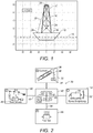
- FIGURE 1 there is shown a drilling ship 10 as illustrated as floating on a body of water 12.
- the drilling ship 10 is utilized in association with heave-compensating drawworks 14.
- a derrick 16 extends upwardly from the deck 18 of ship 10.
- a sheave assembly 20 is positioned at the top of the derrick 16.
- the sheave assembly 20 supports a wire rope 22 extending thereover.
- Wire rope 22 extends downwardly so as to support a hook load 24 at an end of the wire rope 22.
- the hook load 24 is configured so as to support a drill string. It can be seen that the drill string extends to the floor 18 of the ship 10 and downwardly through the body of water 12.
- the drill string will have a bit on the end opposite the hook load 24 which is used for the drilling activities. It is important to note that the weight supported by the hook load 24 and by the wire rope 22 is extremely heavy.
- a winch drum 28 is connected to the opposite end of the wire rope 22 and supported on the deck 18 of the ship 10. The winch drum 28 is used for paying in and paying out the wire rope 22 in relation to the desired movement of the drill string or the desired weight-on-bit at the end of the drill string.
- the ship 10 Since the water 12 will have wave action thereon, the ship 10 will tend to follow this wave action and heave upwardly and downwardly. Since it is desired to maintain a relatively constant weight-on-bit in association with the drilling activities of the drill string, the sheave assembly 20 and the associated wire rope 22 will need to raise and lower in relation to the wave motion of the water 12. When a wave is encountered and a ship elevates by reaching the crest of the wave, then the sheave assembly 20 and the associated wire rope 22 should be payed out by the winch drum 28 so as to maintain the drill string at a constant position.
- the winch drum 28 when the ship 10 encounters a trough of the wave of water 12, it will be necessary for the winch drum 28 to rotate to draw in the wire rope 22 and to raise the sheave assembly 20 in order to maintain this proper position of the drill string.
- the hook load 24 can also be used for the lowering of the drill string prior to drilling. Under these circumstances, the winch drum 28 will pay out the wire rope 22 so as to properly lower the hook load 24 for the purposes of lowering the drill string to a desired underwater location.
- FIGURE 2 illustrates the energy control system 30 in accordance with the teachings of the present disclosure.
- the hook load 34 is supported on a wire rope 36 extending from sheave 38.
- a power supply 40 provides energy for the controller 42.
- the power supply 40 can be a utility grid 44 or an AC motor 46. Power is delivered from the power supply 40 along line 48 to the controller 42.
- Controller 42 is also connected to a flywheel energy storage system 50.
- the flywheel energy storage system includes a flywheel 52 and an AC motor 54.
- a power sink 56 is connected by line 58 to the controller 42. Power sink 56 can be in the nature of batteries at another location on the drawworks.
- the controller 42 includes a suitable algorithm so as to direct energy to and from the various blocks 32, 40, 50 and 56 in relation to the power demands of the heave-compensation drawworks.
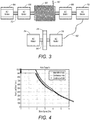
- FIGURE 3 is an illustration of the operation of the flywheel and winch drum of the present disclosure.
- the winch drum 60 has wire rope 62 wound therearound.
- the winch drum 60 is controllably connected to AC motors 64, 66, 68 and 70.
- a common shaft 72 will extend between the AC motors 64, 66, 68 and 70 and be connected to the winch drum 60.
- the AC motors 64, 66, 68 and 70 can deliver the requisite power for the rotation of the winch drum 60 in accordance with the requirements of the heave-compensating drawworks.
- the power of the AC motors 64, 66, 68 and 70 can be delivered by line 82 (or any other conduit) to the AC motors 74 and 76 associated with a flywheel 78.
- a common shaft 80 joins the AC motors 74 and 76 to the flywheel 78.
- the flywheel 78 is in the nature of a steel disk or a disk assembly. As used herein, the flywheel 78 can also be incorporated onto common shaft 72 in any position between any of the AC motors 64, 66, 68 and 70 within the concept of the present disclosure.
- the energy storage system of the present invention is particularly adapted for use with the drawworks-based heave-compensation of a deep-sea drilling vessel. This is because there are highly predictable and period characteristics of ocean swells that readily allow for highly efficient energy recovery. As such, the present disclosure eliminates the need for wasteful dissipation schemes.
- the HITEC AHC-1000 drawworks uses six GEB22 AC induction motors. They convert electrical power into a mechanical torque directly applied to a rotating inertia (the rotor) at a constant efficiency of 95%.
- the motors and drives are able to fully regenerate power at an efficiency of approximately 95%.
- the motors are speed-controlled via PID controllers. The outputs are limited by speed-torque characteristics and major drive parameters (slew rate, speed limits, etc.). Due to the periodic nature of heave compensation, the motors are allowed run at 140% load while heave compensating.
- dual-stator AC motors are used as the AC motors associated with the winch drum.
- These motors are large, low speed, very high torque machines that are directly coupled to the winch drum. As such, it eliminates the necessity for a gear reduction.
- the rotor is ring-shaped and has a concentric outer stator and inner stator. The outer stator delivers 68% of the total torque, while the inner stator delivers the remaining 32%.
- the drawworks requires four such dual-stator AC motors, such as motors 64, 66, 68 and 70.
- Motors 64 and 66 are located on one side of drum 60 while the motors 68 and 78 are located on the opposite side of drum 60.
- These motors 64, 66, 68 and 70 are coupled to each other by a common shaft 72. Since rotational inertia on the high speed side of a gear reduction is effectively multiplied by the square of the gear ratio, this direct drive setup will have a significantly lower total inertia (approximately 35% lower than the GEB22 equipped system) while the overall weight stays roughly the same. This system will also benefit from the elimination of gear backlash, greater redundancy, a lower cost drive system, and high breakdown torque (225% of nominal).
- the hook is assumed to be held absolutely motionless while the ship heaves sinusoidally with heave height H(t). Energy is contained as potential energy in the relative hook height and as kinetic energy in the rotating motors and winch drum. Drum speed is assumed to be exactly proportional with heave speed, with a factor based on the number of line parts N and drum radius R.
- the total ⁇ effective inertia I t stems from the drum inertia plus the total effective inertia of the motors as seen through a reduction of gear ratio GR.
- the flywheel system 78 is a very simple system. It is a simple torque device (an AC induction motor/generator coupled to a large rotational inertia).
- F plate 1 ⁇ 2 C Df ⁇ A V 2
- C Df the shear drag coefficient
- ⁇ fluid density
- A the reference area
- V linear velocity
- the flywheel system has two main goals. First, it should store and reuse regenerated power so as to realize a lower overall average power consumption. Second, it should buffer the equipment's power requirements in such a way that the power source sees a relatively constant load profile free of extreme peaks and valleys. It is desirable to dimension the device such that its energy and power capacity is consistent with the machine's maximum estimated peak-to-peak energy fluctuations and power demand. Since it has been estimated that the energy fluctuation is estimated to be approximately 41 MJ, a flywheel capacity of roughly double that amount will ensure a sufficient energy range. The maximum power to be delivered by the flywheel is roughly equal to the maximum power rating of the equipment it will be used with. In particular, the flywheel system can consist of the same GEB22 AC motors as used in the drawworks.
- the flywheel will include a large steel disc. Motors 74 and 76 face each other so as to drive a flywheel 78 situated in between them. Three of these units are sufficient to provide the power and energy storage capacity required for the heave-compensating drawworks. The motors all operate in parallel.
- the main power source as shown in block 40, is used for power generation.
- the equipment as shown in block 32, is the drawworks system. This equipment 32 can provide power consumption and energy generation or regeneration.
- the flywheel energy storage system as illustrated in block 50, provides power consumption and energy generation or regeneration.
- the excess power sink as illustrated in block 56, which provides solely power consumption.
- the controller 42 utilizes a flywheel control algorithm. The controller 42 will coordinate energy transfer between the systems.
- the controller 42 routs power to and from the blocks 32, 40, 50 and 56 according to the following priorities (in order of importance): (1) the power demand of the equipment in block 32; (2) the flywheel energy storage system 50 operating within its preset limits; (3) the power drawn from the main power source 40 is constant; (4) the flywheel energy storage system 50 contains sufficient energy to supply the next demand peak; (5) the flywheel energy storage system 50 has sufficient "headroom” to absorb the next regeneration peak; and (6) a minimal amount of power is routed to the power sink 56.
- priorities in order of importance: (1) the power demand of the equipment in block 32; (2) the flywheel energy storage system 50 operating within its preset limits; (3) the power drawn from the main power source 40 is constant; (4) the flywheel energy storage system 50 contains sufficient energy to supply the next demand peak; (5) the flywheel energy storage system 50 has sufficient "headroom” to absorb the next regeneration peak; and (6) a minimal amount of power is routed to the power sink 56.
- the energy index is related to the flywheel charge and the power index is related to the power being demanded by the application.
- the amount of power to be transferred along each route is a function of these two indices.
- a surface in three-dimensional space is defined for each route. The value of I E and I P can be seen as coordinates defining a point on this surface. The height of the surface at this point is then a measure of the amount of power to be transferred along that route.
- I E and I P are directly linearly related to the flywheel charge and the power demand of the equipment 32.
- the associated surface has zero height almost everywhere. In other words, when power demand is negative (the drawworks is regenerating) and the flywheel is almost fully charged, the system will only begin to dissipate power through the sink 56.
- the power and energy indices can be directly linearly related to the current power demand or flywheel charge, respectively, or they can be filtered in some way.
- the power transfer is scaled by a factor obtained by passing the power demand signal of the equipment 32 through a low-pass butterworth filter with a cutoff frequency below the machine's typical operating cycle frequency.
- the surface is shaped so that the power is continuously routed at a fairly constant trickle from the power supply 40 to the flywheel energy storage system 50. This will occur at approximately the rate of the machine's average power consumption except for when the power demand is high and flywheel is almost depleted (i.e. where power generation resources are diverted straight to the equipment 32) and when the flywheel energy storage system 50 is near maximum charge.
- main control system 42 Besides the main control system 42, some minor logic can be added to further optimize the system's performance.
- Two such additions are a grid peak limiter, which limits the maximum power draw from the grid to a preset value and a precharge unit which precharges the flywheel to compensate for initial filter start-up transients.
- the system is also easily adaptable to other applications. The most important parameters to consider are those for the low-pass filters (filter order and cut-off frequency).
- the power routing surfaces as developed for this system are generally suitable to most cyclical applications.
- the simulations conducted with these systems were developed in and run in Simulink.
- This is a software package that is used in conjunction with MATLAB (TM). As such, it provides a graphical interface to model highly complex dynamic systems in the form of familiar block diagrams.
- the simulation is divided into two separate parts. First, the drawworks dynamics simulation is run for a certain amount of time. This simulation outputs, among other things, the drawworks' power requirement load profile. This load profile is subsequently used as an input for the simulation of the flywheel dynamics and the flywheel control system. The mathematical nature of the drawworks dynamics simulation is different from that of the flywheel control system.
- the drawworks model is a "stiff" nonlinear differential equation.
- the flywheel control system simulation contains many logic-based components that can change their output between discrete states instantaneously.
- the flywheel control system is simulated using a fixed-step discrete solver.
- a parameters file is provided which includes simulation settings (solver, step time, simulation duration), drawworks parameters (inertias, geometry, speed-torque characteristics, etc.) and flywheel control system settings (power routing surfaces, filter settings, etc.).
- simulation settings solvent, step time, simulation duration
- drawworks parameters inertias, geometry, speed-torque characteristics, etc.
- flywheel control system settings power routing surfaces, filter settings, etc.
- FIGURE 4 illustrates the hoisting capacity verification.
- the hook load can be at its maximum and will decline relative to the block speed. In other words, the amount of hook load in an intermittent hoist is reduced relative to the desired block speed.
- the maximum hook load is less than for the intermittent hoist and will decline at an earlier point than that for an intermittent hoist.
- FIGURE 5 shows the heave-compensation limits calculated through simulation and overlaid onto the scanned AHC 1000 plot.
- the areas where the results diverge slightly from the specifications can be attributed to differing friction factors, motor specifications and control parameters.
- the hook load for the systems is rather inversely related to heave amplitude. Where the heave amplitude is great, then less hook load is possible. However, when heave amplitude is minimal, then a large hook load can be achieved.
- FIGURE 6 illustrates the effect of the flywheel system's start-up transient.
- FIGURE 6 plots the total external power draw of the drawworks. Initially, the flywheel's precharge is supplying most of the power to the drawworks, while external power draw slowly picks up.
- the peak load is reduced by a factor of 10 or more in most cases while average power draw is reduced approximately by a factor of 4.
- the effect of the lower rotational inertia of the direct drive system can be seen in the load profile of FIGURE 6 .
- this effect is overshadowed by the power demanded by the linear heaving motion.
- the drastic reduction in peak power draw means that power production capacity can be reduced, for example, by putting generator sets offline.
- the drawworks is powered by a number of CAT 3516 1280 KW diesel generator sets.
- a 900 ton hook load the bottom plot in FIGURE 9
- six of these gensets would normally need to be online.
- the energy storage system in use only a single genset needs to be online due to the greatly reduced peak power draw.
- FIGURE 7 shows the fuel efficiency curves of these generator sets superimposed on histogram plots of the drawworks' power draw with and without the flywheel system.
- the efficiency curves show that a generator set is most efficient when operating near its maximum power rating.
- the histograms are a measurement of the relative amount of time that the drawworks is demanding a certain amount of power. When unaided by the flywheel device, large amounts of power (up to 7500 KW) are drawn for short periods of time, but the overall power requirement is very low. With the flywheel-equipped drawworks of the present invention, the power usage is much more consistent (approximately 700 KW).
- the consistent power draw and the reduced average load results in a 75% lower fuel consumption with only a single genset online instead of the usual six.
- the reduced fuel use and operational range of the engine/generator sets will result in significantly lower emissions.
Landscapes
- Engineering & Computer Science (AREA)
- Life Sciences & Earth Sciences (AREA)
- Mining & Mineral Resources (AREA)
- Geology (AREA)
- Geochemistry & Mineralogy (AREA)
- General Life Sciences & Earth Sciences (AREA)
- Physics & Mathematics (AREA)
- Environmental & Geological Engineering (AREA)
- Fluid Mechanics (AREA)
- Mechanical Engineering (AREA)
- Combustion & Propulsion (AREA)
- Ocean & Marine Engineering (AREA)
- Chemical & Material Sciences (AREA)
- Power Engineering (AREA)
- Architecture (AREA)
- Civil Engineering (AREA)
- Structural Engineering (AREA)
- Connection Of Motors, Electrical Generators, Mechanical Devices, And The Like (AREA)
- Supply And Distribution Of Alternating Current (AREA)
Claims (7)
- Procédé de gestion de la consommation d'énergie dans une treuil de forage à compensation de pilonnement (14) lors d'opérations de forage en mer, le treuil de forage (14) comportant un tambour de treuil (20) un câble métallique (22), le câble métallique (22) s'étendant autour d'un tambour ensemble poulie (20) et étant relié à un train de tiges de forage, le procédé comprenant les étapes consistant à :faire tourner le tambour de treuil (20) de manière à dérouler le câble métallique (22) et à abaisser le train de tiges de forage vers le bas ;transférer l'énergie du train de tiges de forage abaissé vers un volant (78) de manière à faire tourner ledit volant (78) ;transférer de l'énergie du volant rotatif (78) vers un autre emplacement ; etcompenser le pilonnement du treuil de forage (14) en faisant tourner ledit tambour de treuil (20) par rapport à un mouvement du treuil de forage (14) par rapport au mouvement des vagues, dans lequel l'énergie nécessaire à la rotation du tambour de treuil (20) provient du volant (78).
- Procédé selon la revendication 1, dans lequel l'étape de transfert d'énergie à partir du volant rotatif (78) comprend l'étape consistant à :
relever le train de tiges de forage en faisant passer le câble (22) par-dessus le tambour de treuil (20). - Procédé selon la revendication 1, comprenant en outre les étapes consistant à :connecter un moteur à courant alternatif (64) au tambour de treuil (20) de manière à appliquer des forces de rotation au tambour de treuil (20) ; etraccorder un autre moteur à courant alternatif (66, 68, 70) au volant (78).
- Procédé selon la revendication 3, dans lequel ladite étape consistant à transférer de l'énergie à partir du train de tiges de forage abaissé comprend l'étape consistant à :
transférer de l'énergie du moteur à courant alternatif (64) connecté au tambour de treuil (20) vers ledit autre moteur à courant alternatif (66, 68, 70) connecté au volant (78) . - Procédé selon la revendication 3, dans lequel l'étape consistant à connecter un moteur à courant alternatif (74) comprend les étapes consistant à :coupler ledit tambour de treuil à un premier moteur à courant alternatif (74) par l'intermédiaire d'un arbre (80) situé sur un côté dudit tambour de treuil (20) ; etcoupler ledit tambour de treuil (20) à un second moteur à courant alternatif (76) par l'intermédiaire dudit arbre (80) sur un côté opposé dudit tambour de treuil (20).
- Procédé selon la revendication 1, dans lequel ledit autre emplacement est un système utilitaire (44) sur le treuil de forage (14).
- Procédé selon la revendication 1, dans lequel ledit treuil de forage (14) est situé sur un navire de forage (10), ledit autre emplacement étant un moteur associé à un propulseur du navire de forage (10).
Applications Claiming Priority (2)
| Application Number | Priority Date | Filing Date | Title |
|---|---|---|---|
| US12/553,042 US7923946B2 (en) | 2007-05-18 | 2009-09-02 | Flywheel-based energy storage on a heave-compensating drawworks |
| PCT/US2010/047665 WO2011028895A2 (fr) | 2009-09-02 | 2010-09-02 | Stockage d'énergie dans des volants d'inertie sur un treuil de forage à compensation de pilonnement |
Publications (3)
| Publication Number | Publication Date |
|---|---|
| EP2474078A2 EP2474078A2 (fr) | 2012-07-11 |
| EP2474078A4 EP2474078A4 (fr) | 2017-06-07 |
| EP2474078B1 true EP2474078B1 (fr) | 2019-06-12 |
Family
ID=43661811
Family Applications (1)
| Application Number | Title | Priority Date | Filing Date |
|---|---|---|---|
| EP10814489.0A Active EP2474078B1 (fr) | 2009-09-02 | 2010-09-02 | Stockage d'énergie dans des volants d inertie sur un treuil de forage à compensation de pilonnement |
Country Status (4)
| Country | Link |
|---|---|
| US (1) | US7923946B2 (fr) |
| EP (1) | EP2474078B1 (fr) |
| CA (1) | CA2776138C (fr) |
| WO (1) | WO2011028895A2 (fr) |
Families Citing this family (25)
| Publication number | Priority date | Publication date | Assignee | Title |
|---|---|---|---|---|
| US20090312885A1 (en) * | 2008-06-11 | 2009-12-17 | Buiel Edward R | Management system for drilling rig power supply and storage system |
| US20120146402A1 (en) * | 2010-12-09 | 2012-06-14 | Siemens Industry, Inc. | Control system for regulating bus voltage for an electric shovel |
| EP2503666A3 (fr) * | 2011-02-01 | 2013-04-17 | Siemens Aktiengesellschaft | Système d'alimentation pour commande électrique d'un navire |
| DE102012010760A1 (de) | 2012-05-31 | 2013-12-05 | Wolffkran Holding Ag | Elektrohydraulische Vorrichtung mit Drehstromasynchronmotor zur Verstellung eines Ausleger |
| US9141095B2 (en) * | 2012-08-09 | 2015-09-22 | Caterpillar Inc. | System and method for efficiently operating multiple flywheels |
| US20140077600A1 (en) * | 2012-09-14 | 2014-03-20 | Robert Douglas Cryer | System and method for controlling energy storage and distribution |
| DE102012224188A1 (de) * | 2012-12-21 | 2014-06-26 | Wobben Properties Gmbh | Verfahren zur Steuerung eines Wasserschütz-Antriebs für ein Wasserschütz mit einer elektrischen Maschine, Betriebsschaltung, Wasserschütz-Antrieb und Wasserkraftanlage |
| US9688516B2 (en) | 2013-03-15 | 2017-06-27 | Oil States Industries, Inc. | Elastomeric load compensators for load compensation of cranes |
| DK178120B1 (en) | 2013-04-18 | 2015-06-01 | A P Møller Mærsk As | An Offshore Floating Vessel and a Method of Operating the Same |
| WO2014209131A1 (fr) * | 2013-06-25 | 2014-12-31 | National Oilwell Varco Norway As | Système de levage d'une charge sur un engin de forage en mer |
| EP3134660A1 (fr) | 2014-03-13 | 2017-03-01 | Oil States Industries, Inc. | Compensateur de charge à ensembles ressorts de tension contenus dans un logement tubulaire |
| WO2015138833A1 (fr) * | 2014-03-13 | 2015-09-17 | Canrig Drilling Technology Ltd. | Treuil de forage à entraînement direct à faible inertie |
| US20150372581A1 (en) * | 2014-06-20 | 2015-12-24 | Christopher Michael Morris | Kinetic energy system utilizing multi-size multi-use high speed rotating flywheel |
| DE102015222910A1 (de) * | 2014-11-27 | 2016-06-02 | Robert Bosch Gmbh | Bewegungsausgleichsvorrichtung |
| FR3029712B1 (fr) * | 2014-12-03 | 2017-12-15 | Ifp Energies Now | Systeme d'actionnement lineaire electrique equipe de moyens de stockage d'energie |
| CN104627881B (zh) * | 2015-03-04 | 2017-02-01 | 广东工业大学 | 超深浮式钻井多功能节能型升沉补偿绞车及其工作方法 |
| US10119370B2 (en) * | 2015-06-01 | 2018-11-06 | Schlumberger Technology Corporation | Kinetic energy storage for wellbore completions |
| BR112018016317B1 (pt) * | 2016-02-18 | 2023-10-17 | National Oilwell Varco Norway As | Sistema para distribuição e regeneração de energia, barco que compreende o dito sistema, instalação flutuando ao largo da costa que compreende o dito sistema e método para distribuir energia em um barco por meio do dito sistema |
| NO345631B1 (en) * | 2016-02-26 | 2021-05-18 | Castor Drilling Solution As | A compensator-tensioner system |
| EP3363989B1 (fr) | 2017-02-16 | 2019-03-27 | National Oilwell Varco Norway AS | Unité de forage comprenant un système de compensation de pilonnement électrique |
| WO2018192632A1 (fr) | 2017-04-18 | 2018-10-25 | Maersk Drilling A/S | Systèmes d'alimentation électrique de propulseur et procédés associés |
| EP3501968B1 (fr) * | 2017-12-22 | 2022-08-10 | National Oilwell Varco Norway AS | Appareil pour supporter un volant sur un vaisseau flottant et procédés associés |
| NO20180594A1 (en) * | 2018-04-26 | 2019-08-26 | Kongsberg Maritime CM AS | Electrical machine drive system with flywheel-based energy storage units |
| DE102020204326A1 (de) | 2020-04-02 | 2021-10-07 | Adaptive Balancing Power GmbH | Doppelmotoreinheit für einen Schwungmassenspeicher mit nichtlinearer Ge-samt-Leistungskennlinie |
| US12345135B2 (en) | 2021-06-16 | 2025-07-01 | Onesubsea Ip Uk Limited | Power control system for subsea equipment |
Family Cites Families (13)
| Publication number | Priority date | Publication date | Assignee | Title |
|---|---|---|---|---|
| US3638480A (en) | 1969-11-21 | 1972-02-01 | Bucyrus Erie Co | Dual-stator induction motor torque sensor ac dynamometer |
| FR2600053A1 (fr) * | 1986-06-13 | 1987-12-18 | Beineix Andre | Dispositif automatique de liberation de personnes prisonnieres d'un ascenseur ou similaire en panne |
| DE19608099C1 (de) * | 1996-03-02 | 1997-02-27 | Karlsruhe Forschzent | Schwungrad-Energiespeicher |
| US5712456A (en) * | 1996-04-10 | 1998-01-27 | Otis Elevator Company | Flywheel energy storage for operating elevators |
| DE19709674C1 (de) * | 1997-03-11 | 1998-02-12 | Karlsruhe Forschzent | Schwungrad-Energiespeicher |
| JPH10285835A (ja) * | 1997-03-31 | 1998-10-23 | Nippon Furaihoiile Kk | フライホイール電源装置 |
| US5936375A (en) * | 1997-11-05 | 1999-08-10 | Paceco Corp. | Method for energy storage for load hoisting machinery |
| US6365981B1 (en) * | 1999-11-19 | 2002-04-02 | Mamoru Tokita | Power generation system with flywheel apparatus |
| US6819012B1 (en) * | 2000-06-23 | 2004-11-16 | Christopher W. Gabrys | Flywheel energy storage system |
| US7078880B2 (en) * | 2003-08-15 | 2006-07-18 | Honeywell International, Inc. | Energy storage flywheel voltage regulation and load sharing system and method |
| JP2005080399A (ja) * | 2003-08-29 | 2005-03-24 | Fuji Xerox Co Ltd | 回転駆動装置及びこれを用いた処理装置 |
| US7228942B2 (en) * | 2004-02-06 | 2007-06-12 | Paceco Corp. | Method for energy storage for DC motor powered load hoisting machinery |
| US20080203734A1 (en) * | 2007-02-22 | 2008-08-28 | Mark Francis Grimes | Wellbore rig generator engine power control |
-
2009
- 2009-09-02 US US12/553,042 patent/US7923946B2/en active Active
-
2010
- 2010-09-02 EP EP10814489.0A patent/EP2474078B1/fr active Active
- 2010-09-02 WO PCT/US2010/047665 patent/WO2011028895A2/fr not_active Ceased
- 2010-09-02 CA CA2776138A patent/CA2776138C/fr active Active
Non-Patent Citations (1)
| Title |
|---|
| None * |
Also Published As
| Publication number | Publication date |
|---|---|
| US7923946B2 (en) | 2011-04-12 |
| EP2474078A4 (fr) | 2017-06-07 |
| US20100314168A1 (en) | 2010-12-16 |
| CA2776138C (fr) | 2015-11-17 |
| WO2011028895A3 (fr) | 2011-06-03 |
| WO2011028895A2 (fr) | 2011-03-10 |
| EP2474078A2 (fr) | 2012-07-11 |
| CA2776138A1 (fr) | 2011-03-10 |
Similar Documents
| Publication | Publication Date | Title |
|---|---|---|
| EP2474078B1 (fr) | Stockage d'énergie dans des volants d inertie sur un treuil de forage à compensation de pilonnement | |
| US7633248B1 (en) | Flywheel-based energy storage on a heave-compensating drawworks | |
| CA2678668C (fr) | Commande de moteur d'appareil de forage | |
| US20240113522A1 (en) | Microgrid electric power generation systems and associated methods | |
| US9022358B2 (en) | Two speed direct drive drawworks | |
| US5936375A (en) | Method for energy storage for load hoisting machinery | |
| US9267340B2 (en) | Heave compensating system | |
| US20090312885A1 (en) | Management system for drilling rig power supply and storage system | |
| US20050173198A1 (en) | Energy storage method for load hoisting machinery | |
| CA2753674A1 (fr) | Ensemble d'entrainement et appareil pour treuil | |
| US10696166B2 (en) | Electrically driven machine with reverse power storage | |
| EP2961982B1 (fr) | Stockage d'énergie gravitationnelle potentielle | |
| CA2799104A1 (fr) | Appareil et procede pour la recuperation d'energie hydraulique | |
| JP2017221107A (ja) | 海上プラントのハイブリッド電力供給装置及び方法 | |
| EP3155206A2 (fr) | Treuils et systèmes de levage comportant une compensation de pilonnement | |
| CN106429931A (zh) | 主动式电动波浪补偿起重机的控制系统和控制方法 | |
| US7228942B2 (en) | Method for energy storage for DC motor powered load hoisting machinery | |
| CN112154586A (zh) | 海洋船舶或平台上的动能发电机的与运动状态有关的操作 | |
| CN105129643A (zh) | 钻机单交流变频异步电机直驱绞车系统 | |
| Williams et al. | Hybrid heave drilling technology reduces emissions, operating costs for offshore drilling | |
| CN1063727C (zh) | 矿井提升机的紧急制动 |
Legal Events
| Date | Code | Title | Description |
|---|---|---|---|
| PUAI | Public reference made under article 153(3) epc to a published international application that has entered the european phase |
Free format text: ORIGINAL CODE: 0009012 |
|
| 17P | Request for examination filed |
Effective date: 20120329 |
|
| AK | Designated contracting states |
Kind code of ref document: A2 Designated state(s): AL AT BE BG CH CY CZ DE DK EE ES FI FR GB GR HR HU IE IS IT LI LT LU LV MC MK MT NL NO PL PT RO SE SI SK SM TR |
|
| DAX | Request for extension of the european patent (deleted) | ||
| A4 | Supplementary search report drawn up and despatched |
Effective date: 20170511 |
|
| RIC1 | Information provided on ipc code assigned before grant |
Ipc: E21B 19/00 20060101ALI20170504BHEP Ipc: H02J 3/30 20060101AFI20170504BHEP Ipc: H02P 5/74 20060101ALI20170504BHEP Ipc: H02K 7/02 20060101ALI20170504BHEP Ipc: E21B 41/00 20060101ALI20170504BHEP Ipc: G01V 13/00 20060101ALI20170504BHEP |
|
| STAA | Information on the status of an ep patent application or granted ep patent |
Free format text: STATUS: EXAMINATION IS IN PROGRESS |
|
| 17Q | First examination report despatched |
Effective date: 20180522 |
|
| GRAP | Despatch of communication of intention to grant a patent |
Free format text: ORIGINAL CODE: EPIDOSNIGR1 |
|
| STAA | Information on the status of an ep patent application or granted ep patent |
Free format text: STATUS: GRANT OF PATENT IS INTENDED |
|
| INTG | Intention to grant announced |
Effective date: 20181220 |
|
| GRAS | Grant fee paid |
Free format text: ORIGINAL CODE: EPIDOSNIGR3 |
|
| GRAA | (expected) grant |
Free format text: ORIGINAL CODE: 0009210 |
|
| STAA | Information on the status of an ep patent application or granted ep patent |
Free format text: STATUS: THE PATENT HAS BEEN GRANTED |
|
| AK | Designated contracting states |
Kind code of ref document: B1 Designated state(s): AL AT BE BG CH CY CZ DE DK EE ES FI FR GB GR HR HU IE IS IT LI LT LU LV MC MK MT NL NO PL PT RO SE SI SK SM TR |
|
| REG | Reference to a national code |
Ref country code: GB Ref legal event code: FG4D |
|
| REG | Reference to a national code |
Ref country code: CH Ref legal event code: EP |
|
| REG | Reference to a national code |
Ref country code: AT Ref legal event code: REF Ref document number: 1143848 Country of ref document: AT Kind code of ref document: T Effective date: 20190615 |
|
| REG | Reference to a national code |
Ref country code: DE Ref legal event code: R096 Ref document number: 602010059431 Country of ref document: DE |
|
| REG | Reference to a national code |
Ref country code: IE Ref legal event code: FG4D |
|
| REG | Reference to a national code |
Ref country code: NL Ref legal event code: MP Effective date: 20190612 |
|
| REG | Reference to a national code |
Ref country code: LT Ref legal event code: MG4D |
|
| PG25 | Lapsed in a contracting state [announced via postgrant information from national office to epo] |
Ref country code: AL Free format text: LAPSE BECAUSE OF FAILURE TO SUBMIT A TRANSLATION OF THE DESCRIPTION OR TO PAY THE FEE WITHIN THE PRESCRIBED TIME-LIMIT Effective date: 20190612 Ref country code: ES Free format text: LAPSE BECAUSE OF FAILURE TO SUBMIT A TRANSLATION OF THE DESCRIPTION OR TO PAY THE FEE WITHIN THE PRESCRIBED TIME-LIMIT Effective date: 20190612 Ref country code: SE Free format text: LAPSE BECAUSE OF FAILURE TO SUBMIT A TRANSLATION OF THE DESCRIPTION OR TO PAY THE FEE WITHIN THE PRESCRIBED TIME-LIMIT Effective date: 20190612 Ref country code: HR Free format text: LAPSE BECAUSE OF FAILURE TO SUBMIT A TRANSLATION OF THE DESCRIPTION OR TO PAY THE FEE WITHIN THE PRESCRIBED TIME-LIMIT Effective date: 20190612 Ref country code: NO Free format text: LAPSE BECAUSE OF FAILURE TO SUBMIT A TRANSLATION OF THE DESCRIPTION OR TO PAY THE FEE WITHIN THE PRESCRIBED TIME-LIMIT Effective date: 20190912 Ref country code: FI Free format text: LAPSE BECAUSE OF FAILURE TO SUBMIT A TRANSLATION OF THE DESCRIPTION OR TO PAY THE FEE WITHIN THE PRESCRIBED TIME-LIMIT Effective date: 20190612 Ref country code: LT Free format text: LAPSE BECAUSE OF FAILURE TO SUBMIT A TRANSLATION OF THE DESCRIPTION OR TO PAY THE FEE WITHIN THE PRESCRIBED TIME-LIMIT Effective date: 20190612 |
|
| PG25 | Lapsed in a contracting state [announced via postgrant information from national office to epo] |
Ref country code: LV Free format text: LAPSE BECAUSE OF FAILURE TO SUBMIT A TRANSLATION OF THE DESCRIPTION OR TO PAY THE FEE WITHIN THE PRESCRIBED TIME-LIMIT Effective date: 20190612 Ref country code: BG Free format text: LAPSE BECAUSE OF FAILURE TO SUBMIT A TRANSLATION OF THE DESCRIPTION OR TO PAY THE FEE WITHIN THE PRESCRIBED TIME-LIMIT Effective date: 20190912 Ref country code: GR Free format text: LAPSE BECAUSE OF FAILURE TO SUBMIT A TRANSLATION OF THE DESCRIPTION OR TO PAY THE FEE WITHIN THE PRESCRIBED TIME-LIMIT Effective date: 20190913 |
|
| REG | Reference to a national code |
Ref country code: AT Ref legal event code: MK05 Ref document number: 1143848 Country of ref document: AT Kind code of ref document: T Effective date: 20190612 |
|
| PG25 | Lapsed in a contracting state [announced via postgrant information from national office to epo] |
Ref country code: PT Free format text: LAPSE BECAUSE OF FAILURE TO SUBMIT A TRANSLATION OF THE DESCRIPTION OR TO PAY THE FEE WITHIN THE PRESCRIBED TIME-LIMIT Effective date: 20191014 Ref country code: SK Free format text: LAPSE BECAUSE OF FAILURE TO SUBMIT A TRANSLATION OF THE DESCRIPTION OR TO PAY THE FEE WITHIN THE PRESCRIBED TIME-LIMIT Effective date: 20190612 Ref country code: EE Free format text: LAPSE BECAUSE OF FAILURE TO SUBMIT A TRANSLATION OF THE DESCRIPTION OR TO PAY THE FEE WITHIN THE PRESCRIBED TIME-LIMIT Effective date: 20190612 Ref country code: CZ Free format text: LAPSE BECAUSE OF FAILURE TO SUBMIT A TRANSLATION OF THE DESCRIPTION OR TO PAY THE FEE WITHIN THE PRESCRIBED TIME-LIMIT Effective date: 20190612 Ref country code: AT Free format text: LAPSE BECAUSE OF FAILURE TO SUBMIT A TRANSLATION OF THE DESCRIPTION OR TO PAY THE FEE WITHIN THE PRESCRIBED TIME-LIMIT Effective date: 20190612 Ref country code: NL Free format text: LAPSE BECAUSE OF FAILURE TO SUBMIT A TRANSLATION OF THE DESCRIPTION OR TO PAY THE FEE WITHIN THE PRESCRIBED TIME-LIMIT Effective date: 20190612 Ref country code: RO Free format text: LAPSE BECAUSE OF FAILURE TO SUBMIT A TRANSLATION OF THE DESCRIPTION OR TO PAY THE FEE WITHIN THE PRESCRIBED TIME-LIMIT Effective date: 20190612 |
|
| PG25 | Lapsed in a contracting state [announced via postgrant information from national office to epo] |
Ref country code: IT Free format text: LAPSE BECAUSE OF FAILURE TO SUBMIT A TRANSLATION OF THE DESCRIPTION OR TO PAY THE FEE WITHIN THE PRESCRIBED TIME-LIMIT Effective date: 20190612 Ref country code: SM Free format text: LAPSE BECAUSE OF FAILURE TO SUBMIT A TRANSLATION OF THE DESCRIPTION OR TO PAY THE FEE WITHIN THE PRESCRIBED TIME-LIMIT Effective date: 20190612 Ref country code: IS Free format text: LAPSE BECAUSE OF FAILURE TO SUBMIT A TRANSLATION OF THE DESCRIPTION OR TO PAY THE FEE WITHIN THE PRESCRIBED TIME-LIMIT Effective date: 20191012 |
|
| REG | Reference to a national code |
Ref country code: DE Ref legal event code: R097 Ref document number: 602010059431 Country of ref document: DE |
|
| PG25 | Lapsed in a contracting state [announced via postgrant information from national office to epo] |
Ref country code: TR Free format text: LAPSE BECAUSE OF FAILURE TO SUBMIT A TRANSLATION OF THE DESCRIPTION OR TO PAY THE FEE WITHIN THE PRESCRIBED TIME-LIMIT Effective date: 20190612 |
|
| PLBE | No opposition filed within time limit |
Free format text: ORIGINAL CODE: 0009261 |
|
| STAA | Information on the status of an ep patent application or granted ep patent |
Free format text: STATUS: NO OPPOSITION FILED WITHIN TIME LIMIT |
|
| PG25 | Lapsed in a contracting state [announced via postgrant information from national office to epo] |
Ref country code: PL Free format text: LAPSE BECAUSE OF FAILURE TO SUBMIT A TRANSLATION OF THE DESCRIPTION OR TO PAY THE FEE WITHIN THE PRESCRIBED TIME-LIMIT Effective date: 20190612 Ref country code: DK Free format text: LAPSE BECAUSE OF FAILURE TO SUBMIT A TRANSLATION OF THE DESCRIPTION OR TO PAY THE FEE WITHIN THE PRESCRIBED TIME-LIMIT Effective date: 20190612 |
|
| 26N | No opposition filed |
Effective date: 20200313 |
|
| PG25 | Lapsed in a contracting state [announced via postgrant information from national office to epo] |
Ref country code: MC Free format text: LAPSE BECAUSE OF FAILURE TO SUBMIT A TRANSLATION OF THE DESCRIPTION OR TO PAY THE FEE WITHIN THE PRESCRIBED TIME-LIMIT Effective date: 20190612 Ref country code: IS Free format text: LAPSE BECAUSE OF FAILURE TO SUBMIT A TRANSLATION OF THE DESCRIPTION OR TO PAY THE FEE WITHIN THE PRESCRIBED TIME-LIMIT Effective date: 20200224 Ref country code: SI Free format text: LAPSE BECAUSE OF FAILURE TO SUBMIT A TRANSLATION OF THE DESCRIPTION OR TO PAY THE FEE WITHIN THE PRESCRIBED TIME-LIMIT Effective date: 20190612 |
|
| REG | Reference to a national code |
Ref country code: CH Ref legal event code: PL |
|
| PG2D | Information on lapse in contracting state deleted |
Ref country code: IS |
|
| PG25 | Lapsed in a contracting state [announced via postgrant information from national office to epo] |
Ref country code: IE Free format text: LAPSE BECAUSE OF NON-PAYMENT OF DUE FEES Effective date: 20190902 Ref country code: LU Free format text: LAPSE BECAUSE OF NON-PAYMENT OF DUE FEES Effective date: 20190902 Ref country code: LI Free format text: LAPSE BECAUSE OF NON-PAYMENT OF DUE FEES Effective date: 20190930 Ref country code: CH Free format text: LAPSE BECAUSE OF NON-PAYMENT OF DUE FEES Effective date: 20190930 |
|
| REG | Reference to a national code |
Ref country code: BE Ref legal event code: MM Effective date: 20190930 |
|
| PG25 | Lapsed in a contracting state [announced via postgrant information from national office to epo] |
Ref country code: BE Free format text: LAPSE BECAUSE OF NON-PAYMENT OF DUE FEES Effective date: 20190930 |
|
| PG25 | Lapsed in a contracting state [announced via postgrant information from national office to epo] |
Ref country code: CY Free format text: LAPSE BECAUSE OF FAILURE TO SUBMIT A TRANSLATION OF THE DESCRIPTION OR TO PAY THE FEE WITHIN THE PRESCRIBED TIME-LIMIT Effective date: 20190612 |
|
| PG25 | Lapsed in a contracting state [announced via postgrant information from national office to epo] |
Ref country code: HU Free format text: LAPSE BECAUSE OF FAILURE TO SUBMIT A TRANSLATION OF THE DESCRIPTION OR TO PAY THE FEE WITHIN THE PRESCRIBED TIME-LIMIT; INVALID AB INITIO Effective date: 20100902 Ref country code: MT Free format text: LAPSE BECAUSE OF FAILURE TO SUBMIT A TRANSLATION OF THE DESCRIPTION OR TO PAY THE FEE WITHIN THE PRESCRIBED TIME-LIMIT Effective date: 20190612 |
|
| REG | Reference to a national code |
Ref country code: GB Ref legal event code: 732E Free format text: REGISTERED BETWEEN 20220106 AND 20220112 |
|
| REG | Reference to a national code |
Ref country code: DE Ref legal event code: R081 Ref document number: 602010059431 Country of ref document: DE Owner name: NABORS DRILLING TECHNOLOGIES USA, INC. (N.D.GE, US Free format text: FORMER OWNER: WILLIAMS, KEVIN R., CYPRESS, TEX., US Ref country code: DE Ref legal event code: R082 Ref document number: 602010059431 Country of ref document: DE Representative=s name: MEWBURN ELLIS LLP, DE |
|
| PG25 | Lapsed in a contracting state [announced via postgrant information from national office to epo] |
Ref country code: MK Free format text: LAPSE BECAUSE OF FAILURE TO SUBMIT A TRANSLATION OF THE DESCRIPTION OR TO PAY THE FEE WITHIN THE PRESCRIBED TIME-LIMIT Effective date: 20190612 |
|
| PGFP | Annual fee paid to national office [announced via postgrant information from national office to epo] |
Ref country code: DE Payment date: 20250926 Year of fee payment: 16 |
|
| PGFP | Annual fee paid to national office [announced via postgrant information from national office to epo] |
Ref country code: GB Payment date: 20250923 Year of fee payment: 16 |
|
| PGFP | Annual fee paid to national office [announced via postgrant information from national office to epo] |
Ref country code: FR Payment date: 20250925 Year of fee payment: 16 |