EP2126276B1 - Soupape - Google Patents
Soupape Download PDFInfo
- Publication number
- EP2126276B1 EP2126276B1 EP20080701833 EP08701833A EP2126276B1 EP 2126276 B1 EP2126276 B1 EP 2126276B1 EP 20080701833 EP20080701833 EP 20080701833 EP 08701833 A EP08701833 A EP 08701833A EP 2126276 B1 EP2126276 B1 EP 2126276B1
- Authority
- EP
- European Patent Office
- Prior art keywords
- piston
- housing
- rotating element
- fluid
- relative
- Prior art date
- Legal status (The legal status is an assumption and is not a legal conclusion. Google has not performed a legal analysis and makes no representation as to the accuracy of the status listed.)
- Active
Links
Images


Classifications
-
- E—FIXED CONSTRUCTIONS
- E21—EARTH OR ROCK DRILLING; MINING
- E21B—EARTH OR ROCK DRILLING; OBTAINING OIL, GAS, WATER, SOLUBLE OR MELTABLE MATERIALS OR A SLURRY OF MINERALS FROM WELLS
- E21B23/00—Apparatus for displacing, setting, locking, releasing or removing tools, packers or the like in boreholes or wells
- E21B23/004—Indexing systems for guiding relative movement between telescoping parts of downhole tools
-
- E—FIXED CONSTRUCTIONS
- E21—EARTH OR ROCK DRILLING; MINING
- E21B—EARTH OR ROCK DRILLING; OBTAINING OIL, GAS, WATER, SOLUBLE OR MELTABLE MATERIALS OR A SLURRY OF MINERALS FROM WELLS
- E21B34/00—Valve arrangements for boreholes or wells
- E21B34/06—Valve arrangements for boreholes or wells in wells
- E21B34/10—Valve arrangements for boreholes or wells in wells operated by control fluid supplied from outside the borehole
-
- E—FIXED CONSTRUCTIONS
- E21—EARTH OR ROCK DRILLING; MINING
- E21B—EARTH OR ROCK DRILLING; OBTAINING OIL, GAS, WATER, SOLUBLE OR MELTABLE MATERIALS OR A SLURRY OF MINERALS FROM WELLS
- E21B21/00—Methods or apparatus for flushing boreholes, e.g. by use of exhaust air from motor
- E21B21/10—Valve arrangements in drilling-fluid circulation systems
- E21B21/103—Down-hole by-pass valve arrangements, i.e. between the inside of the drill string and the annulus
-
- Y—GENERAL TAGGING OF NEW TECHNOLOGICAL DEVELOPMENTS; GENERAL TAGGING OF CROSS-SECTIONAL TECHNOLOGIES SPANNING OVER SEVERAL SECTIONS OF THE IPC; TECHNICAL SUBJECTS COVERED BY FORMER USPC CROSS-REFERENCE ART COLLECTIONS [XRACs] AND DIGESTS
- Y10—TECHNICAL SUBJECTS COVERED BY FORMER USPC
- Y10T—TECHNICAL SUBJECTS COVERED BY FORMER US CLASSIFICATION
- Y10T137/00—Fluid handling
- Y10T137/2496—Self-proportioning or correlating systems
- Y10T137/2559—Self-controlled branched flow systems
- Y10T137/2574—Bypass or relief controlled by main line fluid condition
- Y10T137/2579—Flow rate responsive
- Y10T137/2592—Carried choke
-
- Y—GENERAL TAGGING OF NEW TECHNOLOGICAL DEVELOPMENTS; GENERAL TAGGING OF CROSS-SECTIONAL TECHNOLOGIES SPANNING OVER SEVERAL SECTIONS OF THE IPC; TECHNICAL SUBJECTS COVERED BY FORMER USPC CROSS-REFERENCE ART COLLECTIONS [XRACs] AND DIGESTS
- Y10—TECHNICAL SUBJECTS COVERED BY FORMER USPC
- Y10T—TECHNICAL SUBJECTS COVERED BY FORMER US CLASSIFICATION
- Y10T137/00—Fluid handling
- Y10T137/2496—Self-proportioning or correlating systems
- Y10T137/2559—Self-controlled branched flow systems
- Y10T137/265—Plural outflows
- Y10T137/2657—Flow rate responsive
Definitions
- THIS INVENTION relates to a valve, and in particular concerns a bypass valve for use in well bores, during drilling, exploration and the like.
- Debris and cuttings are produced in these processes, and this debris is circulated and transported to the surface by the drilling mud or well bore fluid.
- This fluid is typically pumped from the surface along the centre of the drill pipe, and exits the drill pipe near the milling head into the annulus (i.e. the region within the well bore but external to the drill pipe itself). It will be appreciated that a relatively high pressure is required to maintain this circulation.
- MWD measurement-while-drilling
- a drill string terminates in a hydraulically-set packer, which expands when it is set to press tightly against the inner surface of the bore, thus providing a secure anchoring point for other components further up in the bore.
- a hydraulically-set packer which expands when it is set to press tightly against the inner surface of the bore, thus providing a secure anchoring point for other components further up in the bore.
- one or more shear bolts or wires may be broken to activate the packer, or the packer may be activated by inflation.
- Hydraulically-set packers are activated automatically when the pressure of fluid at the packer reaches a certain level. If, therefore, large quantities of well fluid are circulated into the drill pipe, as discussed above, the hydraulic packer may accidentally be set prematurely.
- a bypass valve is therefore required to allow the well fluid to be circulated to the annulus relatively freely before it is desired to set the packer, but to divert well fluid to the packer under high pressure when the packer is to be set.
- packers can be set with setting tools, and it has also previously been proposed to use a "drop-ball" system, in which a ball is dropped down the drill pipe to activate a switch, which diverts the well fluid to the packer.
- drop-ball systems suffer from certain disadvantages, however, since there is a limit to the number of balls that can be dropped, or in some systems a bore cuts off circulation to the main bore once it has landed on its seat.
- valves using a drop-ball system can generally only be used higher up in the drill string than an MWD tool. This is undesirable, since the fluid that passes through the MWD tool is preferably circulated to the annulus through the valve, and therefore ideally the valve is placed downstream of the MWD tool.
- bypass valves utilise indexing tracks, in which a piston moves within a housing, but one or more protrusions on the external surface of the piston follow guide tracks formed on the inside of a housing.
- a first section of the guide track may be a "zig-zag" shape, so that the piston may be driven up and down a limited distance with respect to the housing and the piston will rotate as it follows the zig-zag track, and during this motion respective apertures formed in the piston and housing are at least partially aligned to allow well fluid to circulate to the annulus.
- the track allows the piston to travel further downwards with respect to the housing, by means of a section of track which extends downward below the main zig-zag pattern, to a position in which the apertures do not align and circulation to the annulus is prevented.
- a section of track which extends downward below the main zig-zag pattern
- one aspect of the present invention provides a valve comprising: a housing having an outer wall; a piston disposed within the outer wall, the piston having a fluid channel formed in an interior thereof; and a control arrangement comprising a rotating element which is rotatable with respect to the housing and the piston, and a driving member which is adapted to drive against the rotating element, characterised in that: in a first rotational orientation of the rotating element, the piston and housing may be driven with respect to one another in a first direction so that the driving member moves with respect to the rotating element and contacts the rotating element to exert a force against the rotating element which tends to drive the rotating element in a direction substantially parallel with the first direction, and relative motion between the piston and the housing is halted by the rotating element contacting a stop element, during which motion the piston remains in a first position or range of positions relative to the housing; and in a second rotational orientation of the rotating element, the piston and housing may be driven with respect to one another so that the piston reaches a second position relative to the housing.
- the housing has at least one outlet formed through the outer wall
- the piston has at least one port allowing communication between the fluid channel and an exterior of the piston
- the piston and housing being slidably movable relative to each other to allow the first position or range of positions of the piston relative to the housing, in which the at least one port is in communication with the at least one outlet of the outer wall, allowing fluid to flow from the fluid channel through the at least one outlet, and the second position of the piston relative to the housing, in which the at least one port is not in communication with the at least one outlet of the outer wall and fluid is prevented from flowing from the fluid channel through the at least one outlet.
- the housing has at least one outlet formed through the outer wall
- the piston has at least one port allowing communication between the fluid channel and an exterior of the piston
- the piston and housing being slidably movable relative to each other to allow the first position or range of positions of the piston relative to the housing, in which at least one port is not in communication with the at least one outlet of the outer wall and fluid is prevented from flowing from the fluid channel through the at least one outlet, and the second position of the piston relative to the housing, in which the at least one port is in communication with the at least one outlet of the outer wall, allowing fluid to flow from the fluid channel through the at least one outlet.
- the piston in the first position or range of positions of the piston relative to the housing, the piston remains substantially within the housing, and in the second position of the piston relative to the housing, a lower end of the piston, or a further element driven by the motion of the piston, protrudes out of the housing.
- the rotating element at least partially surrounds the piston.
- At least one of the rotating element (and the driving member is axially slidable with respect to the piston.
- the driving member and rotating element are provided with respective inclined engaging surfaces, so that the driving element exerts a rotational force on the rotating element when the driving member exerts a force against the rotating element which tends to drive the rotating element in a direction substantially parallel with the first direction.
- the rotating element has a key protruding from a surface thereof, which contacts the stop element when the piston and housing are driven with respect to each other and the rotating element is in the first rotational orientation thereof.
- the valve further comprises a control element having a number of recesses, each of the recesses being shaped to receive the key, a plurality of respective rotational orientations of the rotating element being defined by the key being received in each of the recesses.
- the stop element is formed on an inner surface of the housing, or of an inner member which at least partially surrounds the piston, the arrangement being such that, when the piston and housing are driven with respect to each other and the rotating element is in the first rotational orientation thereof, the key is aligned with the stop element, and when the piston and housing are driven with respect to one another and the rotating element is in the second rotational orientation thereof, the key is not aligned with the stop element.
- the piston and the housing may be driven with respect to one another by an increase in the flow rate of fluid passing through the valve.
- the rotating element (6) moves to a different rotational orientation.
- the rotating element is in the first rotational orientation thereof
- the piston may be driven relative to the housing so that the rotating element moves to the second rotational position thereof.
- Another aspect of the present invention provides a method of providing pressurised fluid to, or controlling, a component, comprising the steps of: providing a valve according to any preceding claim; positioning the component downstream of the valve, so that a fluid may flow through the valve and then to the component when the piston is in the second position relative to the housing, or so that the piston, or another element driven by the motion of the piston, may contact the component when the piston is in the second position relative to the housing; placing the rotating element of the valve in the first rotational orientation thereof; allowing fluid to flow through the valve; increasing the rate of flow of the fluid so that the rotating element moves to the second rotational position; and increasing the rate of flow of the fluid so that the piston moves to the second position relative to the housing.
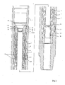
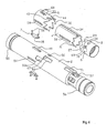
- FIG. 1 a bypass valve embodying the present invention is shown.
- the valve is shown oriented in a vertical bore and so reference will be made to "upper” and “lower” ends (based on the valve as shown in figure 1 ) for convenience.
- the valve comprises a housing 1, which is generally in the shape of an elongate, hollow tube.
- a lower end of the housing 1 is tapered, and has a threaded surface 41 presented on the outer surface thereof for connection to other components.
- the open upper end of the housing has a tapered inner profile, and comprises a further threaded section 40 so that a further component may be fitted inside the housing 1.
- the housing 1 Approximately halfway along its length, the housing 1 has a port 48 formed therethrough, the port 48 being approximately circular in shape.
- outlets 37 are formed through the wall of the housing 1.
- Each of the outlets 37 is approximately circular in shape, and the outlets 37 are evenly spaced around the circumference of the housing 1.
- a filter element 13 having a plurality of smaller apertures is fixed in each outlet 37 and is sealed in place with a seal 14, to prevent larger objects from passing through the outlets 37.
- an inner tubular member 2 Contained within the housing 1 is an inner tubular member 2, which fits snugly within the hollow interior of the housing 1 and is coaxial therewith, with fluid-tight seals being provided at the upper and lower ends by respective circular seals 18, 17, received in grooves 56 formed on the outer surface of the inner tubular member 2.
- the lower end of the inner tubular member 2 rests on a shoulder 60 formed within the housing 1, and the upper end thereof is held in place by a retainer 25, which takes the form of a circlip which is slotted into a receiving groove formed in the inner surface of the housing 1.
- the inner tubular member 2 may therefore not move axially with respect to the outer housing 1.
- a series of apertures 57 are provided, which substantially align with the outlets 37 formed in the housing 1, and a wear ring 66 is provided a short distance above the.apertures 57.
- An upward-facing shoulder 67 runs around the inner circumference of the inner tubular member 2, around halfway along the length thereof:
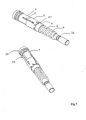
- First and second slots 50,52 are cut into the wall of the inner tubular member 2, each of these slots 50,52 being substantially parallel with the longitudinal axis of the inner tubular member 2, having aligned upper edges shortly above the upward-facing shoulder 67, and having lower edges which are each lower than the shoulder 67.
- the second slot 52 is longer than the first slot 50, having a lower edge which terminates lower down the inner tubular member 2.
- the first and second control slots 50,52 are provided in spaced relation to one another, and are separated from one another by approximately 45° around the circumference of the inner tubular member 2.
- the inner tubular member 2 further has a pair of elongate access apertures 49 formed through opposite sides thereof, around one-third of the way from the upper end.
- the purpose of the access apertures 49 will be described below.
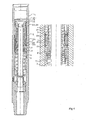
- a hollow piston 3 which is slidably received within the inner tubular member 2 so that a gap having a substantially annular cross-section exists between the inner surface of the inner tubular member 2 and the outer surface of the piston 3.
- the piston 3 is prevented from leaving the inner tubular member 2 at its upper end by a retainer 19, but the space between the retainer 19 and the lower end of the piston 3 is larger than the piston 3, and therefore allows for sliding motion of the piston 3 within the inner tubular member 2.
- a similar seal 23 is provided in a groove 24 to provide a seal at the upper end of the piston 3, and a wear ring 42 is also provided.
- the upper end 55 of the inner tubular member 2 is widened to provide a close fit against the inner surface of the inner tubular member 2.
- a number of ports 36 are formed, which allow communication between the interior of the piston 3 and the exterior thereof.
- the piston 3 is slidable within the inner tubular member 2 between a first range of positions, in which the ports 36 at least partially aligned with the apertures of the inner tubular member 2 so the fluid may flow from the interior of the piston 3 through the ports 36, through the apertures 57 and out of the housing 1 through the outlets 37, and a second position, in which the ports 36 do not align with the outlets of the inner tubular member 2 (in the embodiments shown, by being displaced too far downwards), so that fluid within the interior of the piston 3 may not escape outwardly through the inner tubular member 2.
- the upper end 38 of the piston 3 is provided with a recess into which a variable nozzle 21 can be inserted, the nozzle 21 being sealed with a seal 20 and retained in position with retainer 22.
- the nozzle 21 may be adjusted to vary the operating flow rate regime of the valve, subject to circulating fluid properties, such as density and system pressure limitation.
- System pressure limitation usually occurs as a function of operating depth and thus frictional losses or pressure drop across any other equipment within the system for any given circulating pump capacity.
- the operating pressure drop through the nozzle 21 will be cumulative to the total system circulating pressure.
- the housing 1, inner tubular member 2 and piston 3 provide a continuous axial flow path through the valve through which fluid may flow.
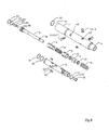
- the control arrangement comprises a driving member 4, which takes the form of a cylindrical collar having a flat upper end, which is fitted around the upper end of the piston 3, an upper edge 62 of the driving member 4 abutting against a downward-facing shoulder 63 provided near the upper end 38 of the piston 3.
- the lower end of the driving member 4 is formed into a saw-tooth profile having a number of symmetrical pointed teeth 31 formed by inclined planes, so that the profile of the lower end resembles a crown.
- eight evenly-spaced teeth 31 are provided.
- a control element 5 fits snugly around the driving member 4 but may slide axially with respect thereto, and also takes the form of a hollow cylinder having a flat upper end.
- a lower end of the control element 5 is formed into a series of asymmetric saw-tooth-shaped teeth 32, each of which has a straight edge 45, which is substantially parallel with the central axis of the cylindrical shape, and an inclined edge 44.
- the control element 5 has eight such teeth 32.
- the outer surface of the control element 5 fits against the inner surface of the inner tubular member 2, and is fixed thereto by means of two plugs 7, which pass through the control apertures 49 formed in the outer surface of the inner tubular member 2, and through registration holes 68 formed in the outer surface of the control element 5.
- the plugs 7 are each held in place by two screws 26, which are received in corresponding threaded holes 33 provided immediately above and below the registration holes 68.
- Noses 35 of the plugs 7 protrude through the registration holes 68 into the interior of the control element 5 and are received in respective elongate grooves 34 which are formed in an outer surface of the driving member 4 and are parallel with the longitudinal axis thereof.
- the driving member 4 may be driven slidably with respect to the control element 5, by movement of the piston 3 relative to the inner tubular member 2, but may not rotate with respect thereto due to the nose 35 of the plug 7 being received in the elongate slot 34.
- the control arrangement also comprises a rotating element, referred to herein as a timing element 6, which again takes the form of a hollow cylinder.
- the timing element 6 has a flat bottom edge, but the top edge is formed into a saw-tooth shape which corresponds to the saw-toothed configuration of the lower end of the driving member 4, having a number of symmetrically-shaped teeth 29 which may mesh with the teeth 31 of the driving member 4.
- the driving member 4 and the timing element 6 have substantially equal diameters and may mesh together completely, their teeth 29,31 interlocking with one another.
- the timing element 6 has an inward-protruding ridge 64 disposed around the inner circumference thereof, the ridge 64 having upper and lower surfaces which are substantially perpendicular to the longitudinal axis of the timing element 6.
- the timing element 6 has a key 27 disposed on an outer surface thereof, and fixed in place.
- the key 27 has a depth which is substantially equal to the thickness of the wall of the control element 5, and takes the form of a right-angled triangle, arranged such that a side edge 69 is substantially parallel with the longitudinal axis of the timing element 6, a bottom edge 70 is parallel with the flat lower edge of the timing element 6, and an inclined edge 30 is set at an angle with respect to these other two edges 69,70, with this angle matching that of the asymmetric teeth 44 of the control element 5.
- the key 27 may be integral with the timing element 6, or may be fixed securely to the outer surface of the timing element 6, for instance by one or more screws, by an adhesive, or by welding.
- the timing element 6 is axially rotatable with respect to the piston 3 and the inner tubular member 2, having ring bearings 10 provided on the upper and lower surfaces of the inwardly-protruding ridge 64.
- an inwardly-protruding lip 62 is provided, having a downward-facing shoulder 61.
- An upper spring 8 is provided in the space between the piston 3 and the driving member 4, and the spring is abutted at its upper end against the downward-facing shoulder 61 and at its lower end against the bearing 10 which is provided on the upper surface of the inward-protruding ridge 64 of the timing element 6.
- the upper spring 8 is a helical compression spring, which biases the timing element 6 downwardly with respect to the driving member 4.
- a lower spring 9 is also provided in the space between the piston 3 and the inner tubular member 2, and abuts at its upper end against the bearing 10 provided on the lower surface of the inwardly-protruding ridge 64 of the timing element 6 and at its lower end against a shoulder 65 which is provided near the lower edge of the inner tubular member 2.
- the lower spring 9 is also a helical compression spring which biases the timing element 6 upwardly with respect to the inner tubular member 2.
- timing element 6 is in a "floating" position both axially and rotationally between the outer surface of the piston 3 and the inner surface of the inner tubular member 2, and is biased into a “rest position” with respect to the other components.
- the saw-teeth 29 of the timing element 6 are spaced apart from the saw teeth 31 of the driving member 4, and these sets of teeth 29, 31 are also rotationally offset with respect to one another.
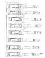
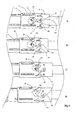
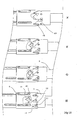
- the timing element 6 As the driving member 4 is driven further downward, as shown in figure 8c , the timing element 6 is pushed further downwards, until the key 27 is pushed beyond the saw teeth 44 of the control element 5. At this point, the timing element 6 rotates with respect to the control element 5 and the driving member 4, due to the forces acting between the inclined edges of the saw teeth 29,32 of these two components. The timing element 6 rotates until the saw teeth 29,32 of the timing element 4 and the driving member 4 mesh completely together, as shown in figure 8d . Further downward motion of the driving member 4 and timing element 6 is prevented by the lower edge 70 of the key 27 contacting the upward-facing shoulder 67 which is formed in the inner surface of the inner tubular member 2.
- timing element 6 will again rotate in the same direction as before, with respect to the control element 5, as the inclined surface 30 of the key 27 slides along the inclined surface 44 of the second saw tooth 32 This continues, as can be seen in figures 8f and 8g , until the key 27 fits snugly between the inclined edge 44 of the second saw tooth 32 and straight edge 45 of the next saw tooth 32 along, as can be seen in figure 8h .
- the timing element 6 has rotated with respect to the piston, the inner tubular member 2 and housing 1 by one "notch", corresponding to a rotation of one-eighth of a full turn. It will be appreciated that, if the circulation of well fluid is initiated and subsequently ceased once again, the timing element 6 can be driven to rotate by another increment, and that this process can be repeated.
- the motion thereof is arrested by the bottom edge 70 of the key 27 contacting the upward-facing shoulder 67.
- the relative distances are arranged so that, during this motion which is arrested by the upward-facing shoulder 67, the piston 3 remains within the first range of positions with respect to the housing 1, so that the ports 36 of the piston 3 align at least partially with the apertures in the inner tubular member 2, thus allowing well fluid to flow from the interior of the piston 3 outwardly into the annulus.
- the key 27 aligns with the first control slot 50 formed in the wall of the inner tubular member 2.
- the timing element 6 may slide downwardly, past the upward-facing shoulder 67, until motion thereof is arrested by the lower edge of the first control slot 50.
- the piston 3 is still within the first range of positions with respect to the inner tubular member 2, but the ports 36 of the piston are partially occluded at the lower end of the motion of the piston 3, and this will have an impact on the pressure of the fluid circulating through the valve, which will be detectable at the surface.
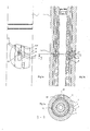
- the key 27 preferably has the numeral "1" prominently displayed thereon, and the numerals 2 through to 8 (indicated by reference numeral 28 in the figures) are also prominently displayed at evenly-spaced positions around the outer circumference of the timing element 6, on a level with the key 27.
- a plug 12 is provided in the port 48 in the housing 1, and this plug may be removed so that the exterior of the timing element 6 may be inspected.
- the arrangement is advantageously such that, when the key 27 with the reference numeral "1" displayed thereon can be seen (as shown in figure 3a ), the key 1 is in a predetermined initial position.
- the plug 12 may then be inserted and sealed with a seal 11 and a retainer 47, so that a nose 43 thereof fits into the port 48, and the relative rotational orientation of the timing element 6 within the housing 1 is known.
- a check is provided by the fact that, after six increases in well fluid circulation, the motion of the piston 3 will result in a detectable increase in the pressure of well fluid at the surface (as the key 27 aligns with the first control slot 50) and when this happens the operator knows that the timing element 6 is one "notch" from alignment with the second control slot 52.
- the piston 3 does not rotate with respect to the inner tubular member 2, or with respect to the housing 1. Only the timing element 6 rotates, and this is provided with bearings 10 as discussed above, to ease this rotation. Damage to the piston 3 or other components by rotational forces is therefore minimised or avoided.
- the driving member 4, control element 5 and timing element 6 of the valve described and depicted in the figures each have eight teeth, although this need not be the case.
- the number of teeth may vary in dependence upon the size of the valve (a larger valve may require more teeth, and a smaller valve may require fewer) and on functional requirements, since more teeth will need to be provided if a particular job necessitates more rounds of increasing and decreasing well fluid circulation before the valve moves to its final position.
- the valve may be used to activate further components by physically contacting them, directly, or indirectly, rather than by supplying fluid at a particular pressure.
- a lower end of the piston or a further component which is driven by the motion of the piston
- a drill string could include a drilling head adapted to drill an initial bore having a relatively low diameter (e.g. 21.6cm (81 ⁇ 2 inches)), and this could be followed by an under reamer adapted to enlarge to the initial bore to a greater diameter (for instance 31.1 cm (121 ⁇ 4 inches)), with the valve being located above the under reamer.
- the under reamer is not activated, and only the drilling head is operational.
- the valve is manipulated as described above to cause the piston to perform a long stroke, and a lower end of the piston comes into contact with, and activates, the under reamer. This could be achieved, for example, by the piston depressing a piston within the under reamer, or by pushing against a sleeve which cuts through one or more shear pins, although a skilled person will appreciate that other methods are also possible.
- the circulation of fluid to the annulus is not essential, and so the ports in the piston may be absent. However, it is preferred that the ports are retained, as the ability to circulate fluid to the annulus is useful in many circumstances.
- the valve may initially be in the "closed" configuration, so that fluid may not circulate from the valve to the annulus and is delivered to the drilling head. However, once the under reamer has been activated, it is desirable for fluid to be delivered both to the drilling head and to the annulus, to aid in removal of waste matter, and so the valve may be configured such that ports in the piston are aligned with outlets in the housing at the furthest point of the long stroke.
- a greater quantity of fluid may be circulated from the valve than through the drilling head (for instance, in a ratio of 60:40, although this ratio will be determined by the ratio of the flow area of drilling head to the flow area of the circulating ports).
- the reciprocal movement is used to operate a valve which is normally in an "open” position into a closed position, which may be reset to the open position by decreasing the pressure in the well fluid.
- the valve may normally be open and may be moved into the closed position as discussed above, such that it remains in the closed position once the pressure in the well fluid drops.
- the valve may also be in a "closed" default position, and may be moved to the open position by reciprocal motion as discussed above.
- the inner tubular member may be absent, and that internal features of the inner tubular member may instead be formed directly onto the inner surface of the housing.
Landscapes
- Engineering & Computer Science (AREA)
- Life Sciences & Earth Sciences (AREA)
- Geology (AREA)
- Mining & Mineral Resources (AREA)
- Physics & Mathematics (AREA)
- Environmental & Geological Engineering (AREA)
- Fluid Mechanics (AREA)
- General Life Sciences & Earth Sciences (AREA)
- Geochemistry & Mineralogy (AREA)
- Mechanical Engineering (AREA)
- Sliding Valves (AREA)
- Fluid-Driven Valves (AREA)
- Multiple-Way Valves (AREA)
- Compressor (AREA)
- Nitrogen Condensed Heterocyclic Rings (AREA)
- Polymers With Sulfur, Phosphorus Or Metals In The Main Chain (AREA)
- Separation By Low-Temperature Treatments (AREA)
- Electrical Discharge Machining, Electrochemical Machining, And Combined Machining (AREA)
- External Artificial Organs (AREA)
- Valve-Gear Or Valve Arrangements (AREA)
- Preventing Unauthorised Actuation Of Valves (AREA)
- Magnetically Actuated Valves (AREA)
- Electrically Driven Valve-Operating Means (AREA)
- Temperature-Responsive Valves (AREA)
Claims (14)
- Une soupape se composant des éléments suivants :un boîtier (1) ayant une paroi extérieure ;un piston (3) disposé à l'intérieur de la paroi extérieure, le piston (3) ayant une rainure de liquide à l'intérieur ; etun dispositif de commande se composant d'un élément rotatif (6) pouvant tourner par rapport au boîtier (1) et au piston (3), et d'un élément d'entraînement (4) adapté pour effectuer l'entraînement contre l'élément rotatif (6), se caractérisant par ce qui suit :dans une première orientation rotationnelle de l'élément rotatif (6), le piston (3) et le boîtier (1) peuvent être entraînés l'un par rapport à l'autre dans une première direction de manière telle que l'élément d'entraînement (4) se déplace par rapport à l'élément rotatif (6) et entre en contact avec l'élément rotatif (6) de façon à exercer une force contre l'élément rotatif (6), ce qui a tendance à entraîner l'élément rotatif (6) dans une direction pour l'essentiel parallèle à la première, et le mouvement relatif entre le piston (3) et le boîtier (1) est interrompu par l'élément rotatif (6) qui entre en contact avec un élément d'arrêt (67), le piston (3) restant dans une première position ou gamme de positions par rapport au boîtier (1) pendant ce mouvement ; etdans une deuxième orientation rotationnelle de l'élément rotatif (6), le piston (3) et le boîtier (1) peuvent être entraînés l'un par rapport à l'autre de façon telle que le piston (3) parvienne à une deuxième position par rapport au boîtier (1).
- Une soupape conforme à la revendication 1, dans laquelle le boîtier (1) possède au moins une sortie (37) dans la paroi extérieure, et le piston (3) possède au moins une ouverture (36) autorisant la communication entre la rainure de liquide et l'extérieur du piston (3), le piston (3) et le boîtier (1) pouvant coulisser l'un par rapport à l'autre pour autoriser la première position ou gamme de positions du piston (3) par rapport au boîtier (1), position dans laquelle la ou les ouvertures (36) sont en communication avec au moins une sortie (37) de la paroi extérieure, ce qui permet au liquide de s'écouler de la rainure de liquide par la ou les sorties (37), et la deuxième position du piston (3) par rapport au boîtier (1), position dans laquelle la ou les ouvertures (36) ne sont pas en communication avec la ou les sorties (37) de la paroi extérieure et le liquide ne peut pas s'écouler de la rainure de liquide par la ou les sorties (37).
- Une soupape conforme à la revendication 1, dans laquelle le boîtier (1) possède au moins une sortie (37) dans la paroi extérieure, et le piston (3) possède au moins une ouverture (36) autorisant la communication entre la rainure de liquide et l'extérieur du piston (3), le piston (3) et le boîtier (1) pouvant coulisser l'un par rapport à l'autre pour autoriser la première position ou gamme de positions du piston (3) par rapport au boîtier (1), position dans laquelle au moins une ouverture (36) n'est pas en communication avec la ou les sorties (37) de la paroi extérieure et le liquide ne peut pas s'écouler de la rainure de liquide par la ou les sorties (37), et la deuxième position du piston (3) par rapport au boîtier (1), position dans laquelle la ou les ouvertures (36) sont en communication avec la ou les sorties (37) de la paroi extérieure, ce qui permet au liquide de s'écouler de la rainure de liquide par la ou les sorties (37).
- Une soupape conforme à n'importe laquelle des revendications précédentes, dans laquelle, dans la première position ou gamme de positions du piston (3) par rapport au boîtier (1), le piston (3) reste pour l'essentiel à l'intérieur du boîtier (1) et, dans la deuxième position du piston (3) par rapport au boîtier (1), une extrémité inférieure du piston (3) ou un autre élément entraîné par le mouvement du piston (3) dépasse du boîtier (1).
- Une soupape conforme à n'importe laquelle des revendications précédentes, dans laquelle l'élément rotatif (6) entoure au moins en partie le piston (3).
- Une soupape conforme à n'importe laquelle des revendications précédentes, dans laquelle l'élément rotatif (6) et/ou l'élément d'entraînement (4) peuvent coulisser axialement par rapport au piston (3).
- Une soupape conforme à n'importe laquelle des revendications précédentes, dans laquelle l'élément d'entraînement (4) et l'élément rotatif (6) sont munis de surfaces d'accouplement inclinées respectives, de manière telle que l'élément d'entraînement (4) exerce une force rotationnelle sur l'élément rotatif (6) lorsque l'élément d'entraînement (4) exerce une force contre l'élément rotatif (6), ce qui a tendance à entraîner l'élément rotatif (6) dans une direction pour l'essentiel parallèle à la première.
- Une soupape conforme à n'importe laquelle des revendications précédentes, dans laquelle l'élément rotatif (6) possède une clé (27) dépassant d'une de ses surfaces, qui entre en contact avec l'élément d'arrêt (67) lorsque le piston (3) et le boîtier (1) sont entraînés l'un par rapport à l'autre et que l'élément rotatif (6) se trouve dans la première orientation rotationnelle.
- Une soupape conforme à la revendication 8, se composant également d'un élément de commande (5) ayant un certain nombre d'évidements, chacun de ces évidements ayant une forme adaptée pour recevoir la clé (27), plusieurs orientations rotationnelles respectives de l'élément rotatif (6) étant définies par la clé (27) reçue dans chacun des évidements.
- Une soupape conforme à n'importe laquelle des revendications précédentes, dans laquelle l'élément d'arrêt (67) est formé sur une surface intérieure du boîtier (1) ou d'un membre intérieur qui entoure au moins en partie le piston (3), l'arrangement étant tel que, lorsque le piston (3) et le boîtier (1) sont entraînés l'un par rapport à l'autre et que l'élément rotatif (6) se trouve dans la première orientation rotationnelle, la clé (27) se trouve dans l'alignement de l'élément d'arrêt (67), et lorsque le piston (3) et le boîtier (1) sont entraînés l'un par rapport à l'autre et que l'élément rotatif (6) se trouve dans la deuxième orientation rotationnelle, la clé (27) ne se trouve pas dans l'alignement de l'élément d'arrêt (67).
- Une soupape conforme à n'importe laquelle des revendications précédentes, dans laquelle le piston (3) et le boîtier (1) peuvent être entraînés l'un par rapport à l'autre par une augmentation du débit de liquide passant par la soupape.
- Une soupape conforme à n'importe laquelle des revendications précédentes, dans laquelle, lorsque l'élément rotatif (6) se trouve dans la première orientation rotationnelle et que le piston (3) est entraîné par rapport au boîtier (1), l'élément rotatif (6) passe à une orientation rotationnelle différente.
- Une soupape conforme à n'importe laquelle des revendications précédentes, dans laquelle, lorsque l'élément rotatif (6) se trouve dans la première orientation rotationnelle, le piston (3) peut être entraîné par rapport au boîtier (1) pour que l'élément rotatif (6) passe à la deuxième position rotationnelle.
- Un procédé permettant de fournir du liquide sous pression à un composant ou de commander un composant, se composant des opérations suivantes :se procurer une soupape conforme à n'importe laquelle des revendications précédentes ;positionner le composant en aval de la soupape, de façon à ce que le liquide puisse passer par la soupape et atteindre le composant lorsque le piston (3) se trouve dans la deuxième position par rapport au boîtier (1) ou pour que le piston (3), ou un autre élément entraîné par le mouvement du piston (3), puisse entrer en contact avec le composant lorsque le piston (3) se trouve dans la deuxième position par rapport au boîtier (1) ;placer l'élément rotatif (6) de la soupape dans la première orientation rotationnelle ;permettre au liquide de passer par la soupape ;augmenter le débit du liquide pour que l'élément rotatif (6) passe à la deuxième position rotationnelle ; etaugmenter le débit du liquide pour que le piston (3) passe à la deuxième position par rapport au boîtier (1).
Applications Claiming Priority (3)
| Application Number | Priority Date | Filing Date | Title |
|---|---|---|---|
| GB0704111A GB0704111D0 (en) | 2007-03-02 | 2007-03-02 | A Bypass valve |
| GB0704218A GB2447093B8 (en) | 2007-03-02 | 2007-03-05 | A valve. |
| PCT/GB2008/000155 WO2008107628A1 (fr) | 2007-03-02 | 2008-01-17 | Soupape |
Publications (2)
| Publication Number | Publication Date |
|---|---|
| EP2126276A1 EP2126276A1 (fr) | 2009-12-02 |
| EP2126276B1 true EP2126276B1 (fr) | 2011-04-20 |
Family
ID=39313190
Family Applications (1)
| Application Number | Title | Priority Date | Filing Date |
|---|---|---|---|
| EP20080701833 Active EP2126276B1 (fr) | 2007-03-02 | 2008-01-17 | Soupape |
Country Status (7)
| Country | Link |
|---|---|
| US (1) | US8893805B2 (fr) |
| EP (1) | EP2126276B1 (fr) |
| AT (1) | ATE506520T1 (fr) |
| CA (1) | CA2677926C (fr) |
| DE (1) | DE602008006372D1 (fr) |
| GB (2) | GB0704111D0 (fr) |
| WO (1) | WO2008107628A1 (fr) |
Cited By (1)
| Publication number | Priority date | Publication date | Assignee | Title |
|---|---|---|---|---|
| WO2021225754A1 (fr) * | 2020-05-04 | 2021-11-11 | Baker Hughes Oilfield Operations Llc | Système de vanne à indexation pour un système d'exploration et de récupération de ressources |
Families Citing this family (12)
| Publication number | Priority date | Publication date | Assignee | Title |
|---|---|---|---|---|
| CA2705295C (fr) * | 2007-11-20 | 2016-06-14 | Jeffery Ronald Clausen | Raccord de circulation a mecanisme d'indexation |
| US8490720B2 (en) * | 2009-08-17 | 2013-07-23 | Tace Parley Hart | Self aligning mud saver valve seat |
| US9453388B2 (en) * | 2012-04-11 | 2016-09-27 | MIT Innovation Sdn Bhd | Apparatus and method to remotely control fluid flow in tubular strings and wellbore annulus |
| US9228402B2 (en) * | 2013-10-04 | 2016-01-05 | Bico Drilling Tools, Inc. | Anti-stall bypass system for downhole motor |
| US9752412B2 (en) * | 2015-04-08 | 2017-09-05 | Superior Energy Services, Llc | Multi-pressure toe valve |
| WO2017138953A1 (fr) * | 2016-02-12 | 2017-08-17 | Halliburton Energy Services, Inc. | Ensemble de verrouillage de dispositif de commande rotatif mécanique |
| MY193337A (en) * | 2017-06-28 | 2022-10-05 | Halliburton Energy Services Inc | Cam indexing apparatus |
| GB2601698B (en) * | 2017-06-28 | 2022-09-28 | Halliburton Energy Services Inc | Cam Indexing Apparatus |
| CN113027365B (zh) * | 2019-12-24 | 2022-12-02 | 中国石油天然气集团有限公司 | 一种钻磨多次开关循环阀 |
| GB2599920B (en) | 2020-10-14 | 2024-05-08 | Mcgarian Bruce | A selectively activatable downhole tool |
| CN113153162B (zh) * | 2021-04-28 | 2024-02-27 | 深圳新速通石油工具有限公司 | 一种非投球自由伸缩式随钻扩眼器 |
| CN115492553A (zh) * | 2021-06-17 | 2022-12-20 | 中国石油化工股份有限公司 | 钻具旁通工具及其使用方法 |
Family Cites Families (9)
| Publication number | Priority date | Publication date | Assignee | Title |
|---|---|---|---|---|
| US4293038A (en) * | 1979-05-24 | 1981-10-06 | Baker International Corporation | Ball valve assembly |
| GB9525008D0 (en) * | 1995-12-07 | 1996-02-07 | Red Baron Oil Tools Rental | Bypass valve |
| GB2307932B (en) * | 1995-12-07 | 1999-08-25 | Red Baron | Bypass valve |
| US5901796A (en) * | 1997-02-03 | 1999-05-11 | Specialty Tools Limited | Circulating sub apparatus |
| GB2362399B (en) * | 2000-05-19 | 2004-06-23 | Smith International | Improved bypass valve |
| GB0021740D0 (en) * | 2000-09-05 | 2000-10-18 | Millennia Engineering Ltd | Downhole control tool |
| GB0106538D0 (en) * | 2001-03-15 | 2001-05-02 | Andergauge Ltd | Downhole tool |
| GB0307237D0 (en) * | 2003-03-28 | 2003-04-30 | Smith International | Wellbore annulus flushing valve |
| AU2003902106A0 (en) * | 2003-05-02 | 2003-05-22 | Drilling Solutions Pty Ltd | Flushing device |
-
2007
- 2007-03-02 GB GB0704111A patent/GB0704111D0/en not_active Ceased
- 2007-03-05 GB GB0704218A patent/GB2447093B8/en active Active
-
2008
- 2008-01-17 WO PCT/GB2008/000155 patent/WO2008107628A1/fr not_active Ceased
- 2008-01-17 EP EP20080701833 patent/EP2126276B1/fr active Active
- 2008-01-17 US US12/526,497 patent/US8893805B2/en active Active
- 2008-01-17 DE DE200860006372 patent/DE602008006372D1/de active Active
- 2008-01-17 AT AT08701833T patent/ATE506520T1/de not_active IP Right Cessation
- 2008-01-17 CA CA2677926A patent/CA2677926C/fr active Active
Cited By (2)
| Publication number | Priority date | Publication date | Assignee | Title |
|---|---|---|---|---|
| WO2021225754A1 (fr) * | 2020-05-04 | 2021-11-11 | Baker Hughes Oilfield Operations Llc | Système de vanne à indexation pour un système d'exploration et de récupération de ressources |
| AU2021267826B2 (en) * | 2020-05-04 | 2024-02-08 | Baker Hughes Oilfield Operations Llc | Indexing valve system for a resource exploration and recovery system |
Also Published As
| Publication number | Publication date |
|---|---|
| US20100193196A1 (en) | 2010-08-05 |
| CA2677926C (fr) | 2015-05-12 |
| GB2447093B (en) | 2010-09-22 |
| CA2677926A1 (fr) | 2008-09-12 |
| WO2008107628A1 (fr) | 2008-09-12 |
| GB0704218D0 (en) | 2007-04-11 |
| ATE506520T1 (de) | 2011-05-15 |
| GB2447093B8 (en) | 2010-10-27 |
| EP2126276A1 (fr) | 2009-12-02 |
| GB0704111D0 (en) | 2007-04-11 |
| DE602008006372D1 (de) | 2011-06-01 |
| US8893805B2 (en) | 2014-11-25 |
| GB2447093A (en) | 2008-09-03 |
Similar Documents
| Publication | Publication Date | Title |
|---|---|---|
| EP2126276B1 (fr) | Soupape | |
| US9279302B2 (en) | Plug counter and downhole tool | |
| US6289999B1 (en) | Fluid flow control devices and methods for selective actuation of valves and hydraulic drilling tools | |
| US8863843B2 (en) | Hydraulic actuation of a downhole tool assembly | |
| AU2015200796B2 (en) | Plug counter, fracing system and method | |
| CA2516649C (fr) | Sabot de forage | |
| US5392858A (en) | Milling apparatus and method for well casing | |
| CA3000012C (fr) | Outil d'activation a pression differentielle et methode d'utilisation | |
| CA2878688C (fr) | Ensembles d'entretien de trou de forage et leurs procedes d'utilisation | |
| EP4227486B1 (fr) | Ensemble de fond de trou avec outil de nettoyage | |
| US20030079913A1 (en) | Apparatus and method for drilling and reaming a borehole | |
| EP3510239B1 (fr) | Outil de coupe de fond de trou et procédé d'utilisation | |
| US12312912B2 (en) | Downhole method and associated apparatus | |
| CA3069274A1 (fr) | Outil et procede de coupe du tubage d'un trou de forage | |
| GB2381550A (en) | Fluid flow control devices and methods for selective actuation of valves and hydraulic drilling tools |
Legal Events
| Date | Code | Title | Description |
|---|---|---|---|
| PUAI | Public reference made under article 153(3) epc to a published international application that has entered the european phase |
Free format text: ORIGINAL CODE: 0009012 |
|
| 17P | Request for examination filed |
Effective date: 20090720 |
|
| AK | Designated contracting states |
Kind code of ref document: A1 Designated state(s): AT BE BG CH CY CZ DE DK EE ES FI FR GB GR HR HU IE IS IT LI LT LU LV MC MT NL NO PL PT RO SE SI SK TR |
|
| DAX | Request for extension of the european patent (deleted) | ||
| 17Q | First examination report despatched |
Effective date: 20100922 |
|
| GRAP | Despatch of communication of intention to grant a patent |
Free format text: ORIGINAL CODE: EPIDOSNIGR1 |
|
| GRAS | Grant fee paid |
Free format text: ORIGINAL CODE: EPIDOSNIGR3 |
|
| GRAA | (expected) grant |
Free format text: ORIGINAL CODE: 0009210 |
|
| AK | Designated contracting states |
Kind code of ref document: B1 Designated state(s): AT BE BG CH CY CZ DE DK EE ES FI FR GB GR HR HU IE IS IT LI LT LU LV MC MT NL NO PL PT RO SE SI SK TR |
|
| REG | Reference to a national code |
Ref country code: GB Ref legal event code: FG4D |
|
| REG | Reference to a national code |
Ref country code: CH Ref legal event code: EP |
|
| REG | Reference to a national code |
Ref country code: IE Ref legal event code: FG4D |
|
| REF | Corresponds to: |
Ref document number: 602008006372 Country of ref document: DE Date of ref document: 20110601 Kind code of ref document: P |
|
| REG | Reference to a national code |
Ref country code: DE Ref legal event code: R096 Ref document number: 602008006372 Country of ref document: DE Effective date: 20110601 |
|
| REG | Reference to a national code |
Ref country code: NL Ref legal event code: VDEP Effective date: 20110420 |
|
| REG | Reference to a national code |
Ref country code: NO Ref legal event code: T2 Effective date: 20110420 |
|
| LTIE | Lt: invalidation of european patent or patent extension |
Effective date: 20110420 |
|
| PG25 | Lapsed in a contracting state [announced via postgrant information from national office to epo] |
Ref country code: LT Free format text: LAPSE BECAUSE OF FAILURE TO SUBMIT A TRANSLATION OF THE DESCRIPTION OR TO PAY THE FEE WITHIN THE PRESCRIBED TIME-LIMIT Effective date: 20110420 Ref country code: HR Free format text: LAPSE BECAUSE OF FAILURE TO SUBMIT A TRANSLATION OF THE DESCRIPTION OR TO PAY THE FEE WITHIN THE PRESCRIBED TIME-LIMIT Effective date: 20110420 Ref country code: PT Free format text: LAPSE BECAUSE OF FAILURE TO SUBMIT A TRANSLATION OF THE DESCRIPTION OR TO PAY THE FEE WITHIN THE PRESCRIBED TIME-LIMIT Effective date: 20110822 Ref country code: SE Free format text: LAPSE BECAUSE OF FAILURE TO SUBMIT A TRANSLATION OF THE DESCRIPTION OR TO PAY THE FEE WITHIN THE PRESCRIBED TIME-LIMIT Effective date: 20110420 |
|
| PG25 | Lapsed in a contracting state [announced via postgrant information from national office to epo] |
Ref country code: CY Free format text: LAPSE BECAUSE OF FAILURE TO SUBMIT A TRANSLATION OF THE DESCRIPTION OR TO PAY THE FEE WITHIN THE PRESCRIBED TIME-LIMIT Effective date: 20110420 Ref country code: FI Free format text: LAPSE BECAUSE OF FAILURE TO SUBMIT A TRANSLATION OF THE DESCRIPTION OR TO PAY THE FEE WITHIN THE PRESCRIBED TIME-LIMIT Effective date: 20110420 Ref country code: SI Free format text: LAPSE BECAUSE OF FAILURE TO SUBMIT A TRANSLATION OF THE DESCRIPTION OR TO PAY THE FEE WITHIN THE PRESCRIBED TIME-LIMIT Effective date: 20110420 Ref country code: LV Free format text: LAPSE BECAUSE OF FAILURE TO SUBMIT A TRANSLATION OF THE DESCRIPTION OR TO PAY THE FEE WITHIN THE PRESCRIBED TIME-LIMIT Effective date: 20110420 Ref country code: ES Free format text: LAPSE BECAUSE OF FAILURE TO SUBMIT A TRANSLATION OF THE DESCRIPTION OR TO PAY THE FEE WITHIN THE PRESCRIBED TIME-LIMIT Effective date: 20110731 Ref country code: AT Free format text: LAPSE BECAUSE OF FAILURE TO SUBMIT A TRANSLATION OF THE DESCRIPTION OR TO PAY THE FEE WITHIN THE PRESCRIBED TIME-LIMIT Effective date: 20110420 Ref country code: IS Free format text: LAPSE BECAUSE OF FAILURE TO SUBMIT A TRANSLATION OF THE DESCRIPTION OR TO PAY THE FEE WITHIN THE PRESCRIBED TIME-LIMIT Effective date: 20110820 Ref country code: BE Free format text: LAPSE BECAUSE OF FAILURE TO SUBMIT A TRANSLATION OF THE DESCRIPTION OR TO PAY THE FEE WITHIN THE PRESCRIBED TIME-LIMIT Effective date: 20110420 Ref country code: GR Free format text: LAPSE BECAUSE OF FAILURE TO SUBMIT A TRANSLATION OF THE DESCRIPTION OR TO PAY THE FEE WITHIN THE PRESCRIBED TIME-LIMIT Effective date: 20110721 |
|
| PG25 | Lapsed in a contracting state [announced via postgrant information from national office to epo] |
Ref country code: NL Free format text: LAPSE BECAUSE OF FAILURE TO SUBMIT A TRANSLATION OF THE DESCRIPTION OR TO PAY THE FEE WITHIN THE PRESCRIBED TIME-LIMIT Effective date: 20110420 |
|
| PG25 | Lapsed in a contracting state [announced via postgrant information from national office to epo] |
Ref country code: CZ Free format text: LAPSE BECAUSE OF FAILURE TO SUBMIT A TRANSLATION OF THE DESCRIPTION OR TO PAY THE FEE WITHIN THE PRESCRIBED TIME-LIMIT Effective date: 20110420 Ref country code: EE Free format text: LAPSE BECAUSE OF FAILURE TO SUBMIT A TRANSLATION OF THE DESCRIPTION OR TO PAY THE FEE WITHIN THE PRESCRIBED TIME-LIMIT Effective date: 20110420 |
|
| PLBE | No opposition filed within time limit |
Free format text: ORIGINAL CODE: 0009261 |
|
| STAA | Information on the status of an ep patent application or granted ep patent |
Free format text: STATUS: NO OPPOSITION FILED WITHIN TIME LIMIT |
|
| PG25 | Lapsed in a contracting state [announced via postgrant information from national office to epo] |
Ref country code: DK Free format text: LAPSE BECAUSE OF FAILURE TO SUBMIT A TRANSLATION OF THE DESCRIPTION OR TO PAY THE FEE WITHIN THE PRESCRIBED TIME-LIMIT Effective date: 20110420 Ref country code: SK Free format text: LAPSE BECAUSE OF FAILURE TO SUBMIT A TRANSLATION OF THE DESCRIPTION OR TO PAY THE FEE WITHIN THE PRESCRIBED TIME-LIMIT Effective date: 20110420 Ref country code: PL Free format text: LAPSE BECAUSE OF FAILURE TO SUBMIT A TRANSLATION OF THE DESCRIPTION OR TO PAY THE FEE WITHIN THE PRESCRIBED TIME-LIMIT Effective date: 20110420 Ref country code: RO Free format text: LAPSE BECAUSE OF FAILURE TO SUBMIT A TRANSLATION OF THE DESCRIPTION OR TO PAY THE FEE WITHIN THE PRESCRIBED TIME-LIMIT Effective date: 20110420 |
|
| 26N | No opposition filed |
Effective date: 20120123 |
|
| REG | Reference to a national code |
Ref country code: DE Ref legal event code: R097 Ref document number: 602008006372 Country of ref document: DE Effective date: 20120123 |
|
| PG25 | Lapsed in a contracting state [announced via postgrant information from national office to epo] |
Ref country code: IT Free format text: LAPSE BECAUSE OF FAILURE TO SUBMIT A TRANSLATION OF THE DESCRIPTION OR TO PAY THE FEE WITHIN THE PRESCRIBED TIME-LIMIT Effective date: 20110420 |
|
| PG25 | Lapsed in a contracting state [announced via postgrant information from national office to epo] |
Ref country code: MC Free format text: LAPSE BECAUSE OF NON-PAYMENT OF DUE FEES Effective date: 20120131 |
|
| REG | Reference to a national code |
Ref country code: CH Ref legal event code: PL |
|
| REG | Reference to a national code |
Ref country code: IE Ref legal event code: MM4A |
|
| PG25 | Lapsed in a contracting state [announced via postgrant information from national office to epo] |
Ref country code: LI Free format text: LAPSE BECAUSE OF NON-PAYMENT OF DUE FEES Effective date: 20120131 Ref country code: DE Free format text: LAPSE BECAUSE OF NON-PAYMENT OF DUE FEES Effective date: 20120801 Ref country code: CH Free format text: LAPSE BECAUSE OF NON-PAYMENT OF DUE FEES Effective date: 20120131 |
|
| REG | Reference to a national code |
Ref country code: DE Ref legal event code: R119 Ref document number: 602008006372 Country of ref document: DE Effective date: 20120801 |
|
| PG25 | Lapsed in a contracting state [announced via postgrant information from national office to epo] |
Ref country code: IE Free format text: LAPSE BECAUSE OF NON-PAYMENT OF DUE FEES Effective date: 20120117 |
|
| PG25 | Lapsed in a contracting state [announced via postgrant information from national office to epo] |
Ref country code: BG Free format text: LAPSE BECAUSE OF FAILURE TO SUBMIT A TRANSLATION OF THE DESCRIPTION OR TO PAY THE FEE WITHIN THE PRESCRIBED TIME-LIMIT Effective date: 20110720 |
|
| PG25 | Lapsed in a contracting state [announced via postgrant information from national office to epo] |
Ref country code: MT Free format text: LAPSE BECAUSE OF FAILURE TO SUBMIT A TRANSLATION OF THE DESCRIPTION OR TO PAY THE FEE WITHIN THE PRESCRIBED TIME-LIMIT Effective date: 20110420 |
|
| PG25 | Lapsed in a contracting state [announced via postgrant information from national office to epo] |
Ref country code: TR Free format text: LAPSE BECAUSE OF FAILURE TO SUBMIT A TRANSLATION OF THE DESCRIPTION OR TO PAY THE FEE WITHIN THE PRESCRIBED TIME-LIMIT Effective date: 20110420 |
|
| PG25 | Lapsed in a contracting state [announced via postgrant information from national office to epo] |
Ref country code: LU Free format text: LAPSE BECAUSE OF NON-PAYMENT OF DUE FEES Effective date: 20120117 |
|
| PG25 | Lapsed in a contracting state [announced via postgrant information from national office to epo] |
Ref country code: HU Free format text: LAPSE BECAUSE OF FAILURE TO SUBMIT A TRANSLATION OF THE DESCRIPTION OR TO PAY THE FEE WITHIN THE PRESCRIBED TIME-LIMIT Effective date: 20080117 |
|
| REG | Reference to a national code |
Ref country code: FR Ref legal event code: PLFP Year of fee payment: 9 |
|
| REG | Reference to a national code |
Ref country code: FR Ref legal event code: PLFP Year of fee payment: 10 |
|
| REG | Reference to a national code |
Ref country code: FR Ref legal event code: PLFP Year of fee payment: 11 |
|
| P01 | Opt-out of the competence of the unified patent court (upc) registered |
Effective date: 20230608 |
|
| REG | Reference to a national code |
Ref country code: GB Ref legal event code: 732E Free format text: REGISTERED BETWEEN 20240905 AND 20240911 |
|
| PGFP | Annual fee paid to national office [announced via postgrant information from national office to epo] |
Ref country code: GB Payment date: 20260106 Year of fee payment: 19 |
|
| PGFP | Annual fee paid to national office [announced via postgrant information from national office to epo] |
Ref country code: NO Payment date: 20260123 Year of fee payment: 19 |
|
| PGFP | Annual fee paid to national office [announced via postgrant information from national office to epo] |
Ref country code: FR Payment date: 20260123 Year of fee payment: 19 |