EP2128448A2 - Turbomachine à boîte de vitesse pour un faisceau de machines, faisceau de machines et boîte de vitesse pour une turbomachine à boîte de vitesse - Google Patents
Turbomachine à boîte de vitesse pour un faisceau de machines, faisceau de machines et boîte de vitesse pour une turbomachine à boîte de vitesse Download PDFInfo
- Publication number
- EP2128448A2 EP2128448A2 EP09006649A EP09006649A EP2128448A2 EP 2128448 A2 EP2128448 A2 EP 2128448A2 EP 09006649 A EP09006649 A EP 09006649A EP 09006649 A EP09006649 A EP 09006649A EP 2128448 A2 EP2128448 A2 EP 2128448A2
- Authority
- EP
- European Patent Office
- Prior art keywords
- pinion
- turbomachine
- compressor
- drive
- gear
- Prior art date
- Legal status (The legal status is an assumption and is not a legal conclusion. Google has not performed a legal analysis and makes no representation as to the accuracy of the status listed.)
- Granted
Links
Images


Classifications
-
- F—MECHANICAL ENGINEERING; LIGHTING; HEATING; WEAPONS; BLASTING
- F04—POSITIVE - DISPLACEMENT MACHINES FOR LIQUIDS; PUMPS FOR LIQUIDS OR ELASTIC FLUIDS
- F04D—NON-POSITIVE-DISPLACEMENT PUMPS
- F04D25/00—Pumping installations or systems
- F04D25/02—Units comprising pumps and their driving means
-
- F—MECHANICAL ENGINEERING; LIGHTING; HEATING; WEAPONS; BLASTING
- F04—POSITIVE - DISPLACEMENT MACHINES FOR LIQUIDS; PUMPS FOR LIQUIDS OR ELASTIC FLUIDS
- F04D—NON-POSITIVE-DISPLACEMENT PUMPS
- F04D25/00—Pumping installations or systems
- F04D25/16—Combinations of two or more pumps ; Producing two or more separate gas flows
- F04D25/163—Combinations of two or more pumps ; Producing two or more separate gas flows driven by a common gearing arrangement
-
- F—MECHANICAL ENGINEERING; LIGHTING; HEATING; WEAPONS; BLASTING
- F05—INDEXING SCHEMES RELATING TO ENGINES OR PUMPS IN VARIOUS SUBCLASSES OF CLASSES F01-F04
- F05D—INDEXING SCHEME FOR ASPECTS RELATING TO NON-POSITIVE-DISPLACEMENT MACHINES OR ENGINES, GAS-TURBINES OR JET-PROPULSION PLANTS
- F05D2220/00—Application
- F05D2220/70—Application in combination with
- F05D2220/72—Application in combination with a steam turbine
-
- F—MECHANICAL ENGINEERING; LIGHTING; HEATING; WEAPONS; BLASTING
- F05—INDEXING SCHEMES RELATING TO ENGINES OR PUMPS IN VARIOUS SUBCLASSES OF CLASSES F01-F04
- F05D—INDEXING SCHEME FOR ASPECTS RELATING TO NON-POSITIVE-DISPLACEMENT MACHINES OR ENGINES, GAS-TURBINES OR JET-PROPULSION PLANTS
- F05D2260/00—Function
- F05D2260/40—Transmission of power
Definitions
- the present invention relates to a geared turbomachinery, in particular radial gear turbomachinery, with integrated load gearbox for a machine train, an integrated load gearbox for such a geared turbomachine, and a machine train comprising such a geared turbomachine and a further compressor, in particular a main compressor.
- a machine train generally has a drive unit, for example a steam turbine, a gas turbine or an expander, in particular a relaxation or residual gas turbine, and one or more of this drive unit driven compressors, for example, for the compression of air or other gases.
- a drive unit for example a steam turbine, a gas turbine or an expander, in particular a relaxation or residual gas turbine, and one or more of this drive unit driven compressors, for example, for the compression of air or other gases.
- machine trains are known in which a doppelantrelbende steam turbine drives on one side a booster compressor with multiple compressor stages and on an opposite side of the steam turbine, a main compressor, which sucks a medium, compresses and the Boosterkompressor with a partial mass flow thereof, the latter, For example, to one to three pressure levels, further compressed.
- the speeds of the steam turbine, main and Boasterkompressor must be coordinated. While for thermodynamic reasons, the speeds of the steam turbine and the compressor stages of the booster compressor should be relatively high, they are for the main compressor due to its large diameter and the associated high centrifugal forces - but lower and previously limited in particular the speed of the steam turbine, which in terms of their Efficiency and their size is disadvantageous.
- the booster compressor as a gear compressor, as he, for example, from the EP 1 691 081 A2 , which is a transmission compressor with an integrated transmission according to the preamble of claim 1 discloses, or the DE 42 41 141 A1 is known to operate its compressor stages at higher speeds than the main compressor. Also in one of the DE 2413 674 C2 known three-stage gear compressor, the Antrisbsdrahayne is translated to higher speeds in the compressor stages in the fast.
- the object of the present invention is to reduce at least one of the aforementioned disadvantages and to improve a machine train.
- a speed-reducing load transmission which is arranged between the drive unit and a compressor, in a gearbox of a geared turbomachine and at the same time to separate it from the compressor.
- a geared turbomachine for a machine train comprises a drive pinion, which is rotatably connected to a drive shaft, one with the Drive pinion engaged large gear and one or more, preferably at least two, in particular three or four turbomachinery rotors.
- These turbomachinery rotors of the transmission turbomachine each comprise a turbomachine shaft, one or more, preferably two rotatably connected to the turbomachine shaft impellers and rotatably connected to the turbomachine shaft Turbomaschinenritzei, wherein the turbomachinery pinion of one or more turbomachinery rotors are engaged with the large wheel.
- An impeller of a turbomachinery rotor can be designed as a compressor or expander wheel.
- two or more compressor impellers of the same turbomachine rotor and / or compressor impellers of different turbomachinery rotors, preferably configured as radial compressors may form compressor stages of the geared turbine engine acting as a transmission compressor.
- Both embodiments may also be combined by, for example, forming at least one turbomachinery rotor equipped with one or more compressor wheels and at least one other turbomachine rotor equipped with one or more expander wheels forming one or more expander stages of the same gear turbomachine, and / or one or more turbomachinery rotors are each equipped with at least one compressor and at least one expander wheel and thus form both a compressor and an expander.
- gear compander Getriebekompressor / expander
- the geared turbomachine now additionally has an output pinion of a speed-reducing power transmission which is non-rotatably connected to an output shaft for driving a compressor drive shaft which can be coupled to this output shaft of a further compressor separate from the geared turbomachine, in particular a main compressor of the engine train, which in particular is designed as a single-shaft compressor can, preferably as an axial compressor, radial compressor, for example, with horizontal and / or vertical parting line or as isothermal compressor, or as a combined axial-radial compressor.
- a transmission turbomachine according to the invention thus combines for the first time a multi-shaft transmission of a gear turbomachine and a load transmission for a compressor separate therefrom.
- An integrated transmission, a geared turbomachine with such an integrated transmission or a machine train according to this first aspect of the present invention has a number of advantages: by the speed-reducing load transmission, a drive unit, such as a steam turbine, a gas turbine or an expander, in particular a relaxation or Restgasturbine, which drives the drive shaft, another compressor, in particular a main compressor, and the turbomachinery rotors of the geared turbomachine are each operated in favorable speed ranges.
- a drive unit such as a steam turbine, a gas turbine or an expander, in particular a relaxation or Restgasturbine, which drives the drive shaft
- another compressor in particular a main compressor
- the turbomachinery rotors of the geared turbomachine are each operated in favorable speed ranges.
- the speed-reducing load gear may reduce a speed of the drive pinion having a gear ratio to a speed of the output pinion which is in the range of 1.25 to 1.45, preferably in the range of 1.3 to 1.4 and more preferably in the range of 1.32 to 1.38.
- a gear ratio is defined in the usual manner as the absolute quotient of drive to output rotational speed, in this case of drive pinion rotational speed divided by output pinion rotational speed, so that a direction of rotation reversal is also described by a positive gear ratio.
- a turbomachine pinion may correspondingly have a gear ratio with the pinion gear which is in the range of 0.28 to 0.54, preferably in the range from 0.30 to 0.52, and more particularly in the range of 0.32 to 0.50, where the gear ratio is the magnitude of the ratio of input pinion speed divided by turbo machine indexing speed.
- a steam turbine may be operated at a rated speed in a range of 4000 to 7000 revolutions per minute (RPM), the turbomachinery rotors of a booster compressor formed as a geared turbomachine at a rated speed in a range of 10,000 to 17,000 rpm, and a main compressor formed as a single-shaft compressor at a rated speed in a range of 2,000 to 6,000 rpm.
- RPM revolutions per minute
- Drive and output pinions form a load gear, via which a large part of the power supplied by the drive unit, which may be in steam turbines, for example in the range of 40 to 80 MW, can be transferred to the other compressor, for example, with a power in the range between 30 to 50 MW is applied.
- a large part of the power supplied by the drive unit which may be in steam turbines, for example in the range of 40 to 80 MW, can be transferred to the other compressor, for example, with a power in the range between 30 to 50 MW is applied.
- at least half, more preferably at least 60% of the power is transmitted from the drive shaft to the output shaft.
- the large wheel distributes the remaining differential power accordingly to the turbomachinery rotors engaged with it.
- the tooth widths of the turbomachinery sprocket and the large gear can be made smaller and are preferably at most 0.91 times the gearing width of the drive sprocket.
- the further compressor is preferably accommodated in a separate housing from a housing of the gear turbomachine.
- the further compressor is preferably spaced in the axial direction of the gear turbomachine, which is particularly advantageous even if the other compressor builds large as a main compressor.
- the load transmission is not included in the housing of the other or main compressor, which may be advantageous vibration technology.
- the geared turbomachine may have one or more expander stages in which one or more turbomachinery rotors are each equipped with at least one, two or more expander wheels.
- a waste medium of the process implemented in the machine train and / or the process medium previously compressed in the main compressor, preferably a partial mass flow thereof can be relaxed and its enthalpy used to drive the further compressor and / or compressor stages of the geared turbomachine.
- the geared turbomachinery which then acts as a booster compressor of the machine train, one or more compressor stages have by one or more turbomachinery rotors are equipped with at least one, two or more Kompresorlauf impartn.
- the compressed in the further compressor medium preferably a partial mass flow from the main compressor, are further compressed to act, for example, after cooling and relaxation as a coolant.
- other media which do not flow through the further compressor can be compressed in compressor stages of the geared turbomachine.
- the geared turbomachine can thus act equally as a working and / or engine, wherein the turbomachine shafts exert a torque on an impeller or be acted upon by this with a torque.
- an electric motor assisting the drive unit and / or driven by the drive unit in particular a motor, a generator or a motor / generator, can be provided, whose electric machine input shaft engages the drive pinion, the large gear, the output pinion or a turbomachine pinion or is coupled to the drive, the output shaft, the shaft of the large gear or a turbine rotor and rotatably connected.
- additional Drive torque introduced by an electric motor in the geared turbomachine or mechanical power available there in a generator converted into electrical power and stored, for example, made available to the machine train or fed into a power grid.
- the flow-through cross sections and thus housing, impeller or blading diameter of the geared turbomachine can be made smaller due to the higher pressures and in particular with only one partial mass flow from the main compressor as with the other compressor.
- a smallest flow-through cross section of the further compressor therefore preferably has at least 1.05 times, preferably at least 1.1 times, and in particular at least 1.2 times, the smallest cross-section through which the geared turbomachine flows.
- turbomachinery pinion and turbomachinery shaft or output pinion and output shaft is presently both a detachable connection, which may for example comprise a splined shaft and / or screws, as well as a permanent connection, in particular a welded joint or an integral training For example, understood as a one-piece master and / or Umformtell.
- a coupling between the output shaft and the disconnectable, separate compressor drive shaft can be realized, for example via a flange connection, a clutch to compensate for axial and / or angular misalignment, and / or a switchable or self-switching clutch, such as an overload clutch.
- both releasably and permanently connected output shafts and compressor drive shafts are referred to as detachable.
- Vortelligent catfish a coupling between the output shaft and compressor drive shaft torsional vibrations. Dampen axial impacts or the like.
- An engaged position in the sense of the present invention comprises on the one hand a direct engagement, ie a combing of teeth, for example single or double helical teeth, of the two mutually engaging elements with each other. Equally, however, this is also an indirect intervention with the interposition of one or more gear stages, in particular Spurrad- and / or planetary gear stages includes, as it is for example from the DE 42 41 141 A1 is known, the disclosure of which is expressly incorporated in this specification.
- a geared turbomachine according to the first aspect of the present invention has two or more turbomachinery rotors
- all of the turbomacer pinions may be engaged with the bull gear, allowing more uniform loading of the bull gear and a narrower gearbox turbomachinery.
- one or more turbomachine pinions may be engaged with the output pinion. This increases the distance of these turbomachinery rotors to those driven by the large wheel, which advantageously increases the structural design freedom of the individual turbomachinery rotors or the compressor and / or expander stages formed by them.
- a rotation axis of the drive pinion, a rotation axis of the large gear and a rotation axis of the output pinion are arranged in a common, preferably substantially horizontal, plane. This advantageously reduces the overall height of the geared turbomachine perpendicular to this plane.
- the axis of rotation of a turbomachine pinion engaged with the large gear and / or the axis of rotation of a turbomachine pinion engaged with the output pinion can also be arranged in this plane and thus further reduce the overall height. If further turbomachine pinions engage the large gear, their axes of rotation are preferably arranged in a further common plane which is parallel to the plane in which the axis of rotation of the large gear lies.
- a gear turbomachine on a multi-part housing which receives the drive pinion, the large gear, the output pinion and the turbomachinery pinion.
- this housing is divided in this plane or these planes. This simplifies installation and maintenance.
- the output pinion and the large gear are arranged in the same transverse plane of the drive pinion.
- This builds the gear turbomachine advantageous axially particularly short.
- the large gear and output pinion can also be arranged in axially offset planes, the large gear or the drive pinion is then advantageously formed in two stages and two different pitch circle diameter for engagement with drive and Turbomaschinenritzeln (in two-stage 1-rad) or for engagement with large gear and output pinion (at two-stage drive pinion).
- Such an arrangement can be narrower, in particular in the plane of the axes of rotation of the drive pinion and the large gear.
- the drive pinion, the large gear, the Turbomaschlornritzeln and the output pinion are mounted axially in a housing of the geared turbomachine, which has for this purpose, for example, two to six thrust bearings.
- the rest of the drive pinion, the large gear, the turbomachine pinions and the output pinion can then be axially supported on these axially mounted in the housing of the gear turbomachine elements, in particular on pressure combs, as shown in the DE 42 41 141 A1 are known, the disclosure of which is expressly incorporated in this specification in this regard.
- the axial thrust of the wheels or of the drive unit can be accommodated with structurally lower expenditure.
- the further compressor can be arranged particularly advantageously on the side of the geared turbomachine opposite the drive unit.
- the drive unit which is thus free on the opposite side of the gear turbomachine, as a steam turbine with axial outflow.
- a condenser downstream of the steam turbine is arranged substantially on the same horizontal plane, which considerably reduces the overall height of such a machine line.
- a steam turbine having an axial outflow is provided as a power plant.
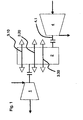
- Fig. 1 . 3 show the essential elements of a machine string according to a first embodiment of the present invention, in which the first and second aspects of the present invention are implemented together.
- Fig. 1 is denoted by 4 designed as an axially aspirated single-shaft compressor main compressor, which sucks air in the manner indicated by a Pfell manner and compressed to, for example, 7 bar.
- a partial mass flow of this compressed air is then supplied in a manner not shown to a first turbomachine rotor 3.10 of a booster compressor, which is designed as a transmission turbomachine 2 explained in more detail below.
- the first turbomachine rotor 3.10 in this case comprises two compressor runners 3.12, 3.13 (indicated by triangles).
- Fig. 3B which sit on a common turbomachine shaft and rotate in unillustrated volute to further compress the supplied air from the main compressor and thus forms two compressor stages of the booster compressor 2. From these, the air is then in a manner not shown a second turbomachinery rotor 3.20 of the booster compressor 2, whose also indicated as triangles two compressor impellers 3.22, 3.23 ( Fig. 3B ) have a smaller diameter and rotate faster than the impellers of the first turbomachine rotor 3.10 to further compress the air and thus form two further compressor stages of the booster compressor 2.
- the air further compressed therein is then supplied in a manner not shown again to a third turbomachine rotor 3.30 of the booster compressor 2, whose two compressor front wheels 3.32, 3.33 (FIG. Fig. 3B ) again have a smaller diameter and turn faster than the impellers of the second turbomachine rotor 3.20 to finally compress the air to a desired final pressure of 75 bar and thus form two further compressor stages of the total six-stage booster compressor 2.
- three turbomachinery rotors 3.10, 3.20 and 3.30 of the booster compressor 2 are structurally analogous.
- turbomachine shafts of the three turbomachinery rotors 3.10, 3.20 and 3.30, on which the wheels 3.12 and 3.13, 3.22 and 3.23 or 3.32 and 3.33 sit each a turbomachinery pinion 3.11, 3.21 and 3.31 rotatably connected, for example, cut on the turbomachine shaft or attached as a separate pinion via a shaft-hub connection to her.
- All three turbomachinery pinions 3.11, 3.21 and 3.31 mesh with a common large 2.2 of the thus formed as a multi-shaft compressor booster compressor 2.
- the turbomachine pinion 3.11 of the first, slowest rotating turbomachinery rotor 3.10 has the largest diameter, 3.31 turbomachinery pinion of the third, fastest rotating turbomachinery rotor 3.30 the smallest diameter.
- the large gear 2.2 is in turn driven by a drive pinion 2.1 smaller diameter, which in a manner not shown rotatably with a Antriebswalla a steam turbine 1 (Fig. Fig. 1 ) or another drive unit, for example a gas turbine or an expander, so that the turbine speed is quickly translated to the turbomachine shafts of the three turbomachinery rotors with different gear ratios.
- a drive pinion 2.1 smaller diameter which in a manner not shown rotatably with a Antriebswalla a steam turbine 1 (Fig. Fig. 1 ) or another drive unit, for example a gas turbine or an expander, so that the turbine speed is quickly translated to the turbomachine shafts of the three turbomachinery rotors with different gear ratios.
- the axis of rotation of a driven pinion 2.3 is arranged in the same horizontal plane in which the axes of rotation of the drive pinion 2.1, the large gear 2.2 and the Turbomaschinenritzel 3.11 are arranged, which with the drive pinion 2.1 on the large 2.2 opposite side is engaged.
- Drive pinion 2.1, large gear 2.2 and output pinion 2.3 are in the same transverse plane (plane of the Fig. 3A ), so that the same toothing of the drive pinion 2.1 meshes both with the large gear 2.2 and the output gear 2.3.
- Fig. 3B indicated schematically, due to the different torque fluxes the tooth width of the turbomachine pinion 3.11, 3.21, 3.31 less than that of the input and output pinion 2.1, 2.3.
- the diameter of the output pinion gear 2.3 is greater than the diameter of the drive pinion 2.1, so that the speed of the steam turbine 1, which drives the seated on its drive shaft drive pinion 2.1, on the output shaft with the output pinion 2.3 is slowed down.
- the output shaft with the output pinion 2.3 is characterized by a in Fig. 1 indicated clutch with a compressor drive shaft 4.1 of the designed as a single-shaft compressor main compressor 4 ( Fig. 1 ), so that the turbine drives it with a reduction in the slow.
- Drive and output pinions 2.1, 2.3 thus form a navzahiunter mecanicdes load transmission, via which the majority of the turbine power is transmitted to the main compressor 4.
- booster compressor 2 and main compressor 4 can be operated simultaneously in optimal speed ranges.
- the speed of the steam turbine 1 may be higher with lower main compressor speed, which improves the efficiency of the steam turbine 1 and allows the use of smaller, faster rotating steam turbines.
- the axes of rotation of the turbomachine pinions 3.21, 3.31 of the second and third turbomachinery rotor 3.20 and 3.30 are in an in Fig. 3A dash-dotted lines indicated further horizontal plane, which is parallel to the plane in which the axes of rotation of input and output pinion 2.1, 2.3, large 2.2 and turbomachinery 3.11 are.
- the housing is also horizontally divided in this plane, so that after placing the middle housing part, the turbomachinery pinions 3.21, 3.31 can be easily mounted in the middle housing part, on soft a third, upper housing part is placed.
- the main compressor 4 has a separate housing from the booster compressor 2 and is connected thereto only via the compressor drive shaft 4.1.
- the two housings of main and Boosterkompressor which rest for example on a concrete or metal foundation, not shown, vibration advantageous advantageous largely decoupled.
- the steam turbine 1 drives the booster compressor 2 and arranged on the opposite side of the main compressor 4 with only one drive shaft.
- a steam turbine with only one shaft advantageously other eigenfrequenzen or critical speeds - in particular, the range between adjacent natural frequencies and critical speeds, of which a sufficient distance is to be maintained during operation, to resonance problems avoid, advantageously increased and so the permissible operating range can be extended.
- booster compressor 2 and main compressor 4 on the same side of the steam turbine 1 allows an in Fig. 1 indicated by an arrow axial outflow from the steam turbine 1 on the main compressor 4 and booster compressor 2 opposite side (to the left in Fig. 1 ) according to the second aspect of the present invention.
- the efficiency of the steam turbine 1 improves advantageously.
- the axial exhaust steam from the steam turbine 1 flows into a downstream of this condenser (not shown).
- this condenser In contrast to conventional machine trains in which booster compressor and main compressor are arranged on both sides of the steam turbine, resulting in a radial outflow and thus an arrangement of a downstream condenser in the vertical direction above or below the plane of the steam turbine and accordingly a two-storey foundation structure with a corresponding vertical height due the capacitor of a machine train according to the second aspect of the present invention due to the axial outflow of the steam turbine 1 are arranged substantially on the same horizontal plane as this.
- the arrangement of the axes of rotation of input, output pinion, large gear and turbomachinery pinion in the same or parallel to this further, vertically above horizontal plane advantageously contributes to.
- Fig. 2 . 4 show in Fig.1 . 3 corresponding representation of the essential elements of a machine string according to a second embodiment of the present invention, which substantially corresponds to the first embodiment and in which also the first and second aspects of the present invention are implemented together.
- Elements that correspond to the first embodiment are designated by identical reference symbols, so that reference is made in this regard to the above explanations regarding the substantially identical first embodiment, and subsequently only the differences between the first and second embodiments are discussed.
- the main compressor 4 sucks radially in the second embodiment.
- the booster compressor 2 of the second embodiment is different from the booster compressor 2 of the first embodiment in the arrangement of the second and third turbomachinery rotors 3.20, 3.30. While the axes of rotation of their turbomachinery pinions 3.21, 3.31, as in Fig. 3A shown, lie in a common further horizontal plane, which is parallel to the plane of the axes of rotation of input, output pinion and large gear, are in the second embodiment after Fig.
- turbomachine pinion 3.11, 3.21 of the first and second turbomachinery rotor 3.10, 3.20 with the large 2.2 in engagement the turbomachine 3.11,3.21 of the first and second turbomachinery rotor 3.10, 3.20 and the drive pinion 2.1 in the circumferential direction preferably offset by 90 ° in engagement with the large gear 2.2, ie the axis of rotation of the second turbomachine scratch 3.21 horizontally between the axes of rotation of the drive pinion 2.1 and the turbine engine sprocket 3.11 the first turbomazl rotor and vertically above the common horizontal plane of input, output pinion 2.1, 2.3, large 2.2 and turbomachine 3.11.
- the direction of rotation can also be oriented differently by the interposition of further gear stages between input, output pinion, large gear and / or turbomachinery pinions.
- the turbomachine pinions it is possible to form the turbomachine pinions as ring gears of a planetary gear, which drives the turbomachine shaft, as shown in the DE 42 41 141 A1 is described, the disclosure of which is expressly included in the present description.
- Fig. 5 shows in Fig. 3B . 4B corresponding representation of the essential elements of a transmission arrangement of a Getrerteneturbomaschine with integrated transmission according to a third embodiment of the present invention, which in terms of what is true with the first and second Ausfahrung and in which also the first and second aspects of the present invention are implemented together.
- Elements which correspond to the first and second embodiments are designated by identical reference numerals, so that in this respect reference is made to the above explanations to the substantially identical first and second embodiments and only the differences between the first, second and third embodiments are discussed below.
- the first turbomachine rotor 3.10 is replaced by an electric machine input shaft 5.1, which is connected via a coupling with an electric machine 5, for example an electric motor or generator.
- the electric machine input shaft 5.1 has an electric machine pinion 2.4, which instead of the turbomachine pinion 3.11 with the large 2.2 is engaged.
- a suitable choice of the gear ratios between electric machine sprocket 2.4 and large 2.2 for example, a higher speed of the drive pinion 2.1 be reduced to a lower speed of the electric machine pinion, which - depending on a grid frequency - for example 3000 or 3600 U / min.
- the electric machine 5 is designed as a generator or motor / generator, then mechanical power of the steam turbine 1, which is not required for driving the main compressor 4 and the compressor stages of the gear turbomachine 2, can be converted into electrical energy and fed, for example, into a power supply network.
- an impeller of the third turbomachinery rotor 3.30 is designed as an expander impeller 3.34, the other as in the first and second embodiments as a Komprossorlauf 3.33, which in Fig. 5 indicated by graceful triangles.
- the Getriebeturbamaschine 2 thus has five compressor stages and an expander stage and at the same time acts as a work and as an engine (compander).
- Fig. 6 shows in Fig. 5 corresponding representation of the essential elements of a transmission arrangement of a geared turbomachine with integrated transmission according to a fourth embodiment of the present invention, which substantially coincides with the third embodiment and in which also the first and second aspects of the present invention are implemented together.
- Matching elements are denoted by identical reference numerals, so that reference is made in this regard to the above explanations to the substantially identical third embodiment and will be discussed below only the differences between the third and fourth embodiments.
- turbomachinery pinion 3.21, 3.31 of the second and third turbomachinery rotor 3.20, 3.30 both mesh with the large 2.2 and their axes of rotation are arranged for this purpose in a common horizontal plane in which also a Tellungs- or parting line of the housing of the gear turbomachine. 2
- the turbomachine pinion gear 3.21 of the turbomachinery rotor 3.20 engages the bull gear 2.2
- the turbomachine pinion gear 3.31 of the turbomachinery rotor 3.30 which carries a compressor wheel 3.33 and expander wheel 3.34, engages the output gear 2.3 as well in the second embodiment (see. Fig. 4B ) the case is.
- Fig. 7 shows in Fig. 6 corresponding representation of the essential elements of a transmission arrangement of a geared turbomachine with integrated transmission according to a fifth embodiment of the present invention, which substantially coincides with the fourth embodiment and in which also the first and second aspects of the present invention are implemented together.
- Elements that correspond to the fourth embodiment are designated by identical reference symbols, so that reference is made to the above explanations regarding the substantially identical fourth embodiment and only the differences between the fourth and fifth embodiments are discussed below.
- turbomachine rotor 3.20 whose turbomachine pinion gear 3.21 meshes with the large gear 2.2
- turbomachine rotor 3.30 whose turbomachinery gear 3.31 meshes with the output gear 2.3
- another turbomachine rotor 3.10 provided with two Kompressoriaufmannern 3.12, 3.13, the turbomachine pinion 3.11 on the opposite side of the large wheel 2.2 with the electric toothed pinion 2.4 is engaged.
- both wheels 3.34, 3.35 of the third turbomachinery rotor 3.30 designed as Expanderiauftex what in Fig. 7 is indicated by opposite to the Kompressorlaufrädem 3.12, 3.13, 3.21 and 3.22 opposing triangles.
- the gear turbomachine 2 thus has four compressor stages and two expander stages and also acts as a compander. While in the compressor stages, a Tellmassenstrom the compressed air in the main compressor 4 is further compressed in the Expandericin a medium, for example, incurred in the process of residual gas, and so additional torque to drive the main compressor 4 and the compressor stages of the geared turbomachine 2 in the geared turbine machine. 2 be fed.
- Fig. 2 . 4 are the axes of rotation of Turbomaschinenritzei 3.11, 3.31, the electric machine pinion 2.4, the large gear 2.2, the drive pinion 2.1 and the output pinion 2.3 preferably all in the same horizontal plane of division of the housing of the gear turbomachine. 2
- some or all of the compressor lobes of the gear turbomachine 2 may compress medium, preferably a partial mass flow thereof, that has passed through the main compressor or another medium, such as another process gas.
- the gear turbomachine 2 can also compress different media with its various compressor wheels.
- the steam turbine, the main compressor and the turbomachinery rotors of the geared turbomachine can each be operated in optimum rotational speed ranges which can be matched to one another by appropriate selection of the ratios in the gearbox of the geared turbomachine 2 and the load gearbox 2.1, 2.3.
- the steam turbine can rotate faster via the speed-reducing load transmission, so that its efficiency can be improved and smaller steam turbine sizes can be used.
- turbomachines in particular a gas turbine or an expander such as a relaxation or residual gas turbine can be used.
Landscapes
- Engineering & Computer Science (AREA)
- Mechanical Engineering (AREA)
- General Engineering & Computer Science (AREA)
- Structures Of Non-Positive Displacement Pumps (AREA)
- Gear Transmission (AREA)
- Supercharger (AREA)
Applications Claiming Priority (3)
| Application Number | Priority Date | Filing Date | Title |
|---|---|---|---|
| DE102008025695 | 2008-05-29 | ||
| DE102008030103 | 2008-06-25 | ||
| DE102008031116.2A DE102008031116B4 (de) | 2008-05-29 | 2008-07-01 | Getriebeturbomaschine für einen Maschinenstrang, Maschinenstrang mit und Getriebe für Getriebeturbomaschine |
Publications (3)
| Publication Number | Publication Date |
|---|---|
| EP2128448A2 true EP2128448A2 (fr) | 2009-12-02 |
| EP2128448A3 EP2128448A3 (fr) | 2017-07-26 |
| EP2128448B1 EP2128448B1 (fr) | 2020-06-24 |
Family
ID=41254065
Family Applications (1)
| Application Number | Title | Priority Date | Filing Date |
|---|---|---|---|
| EP09006649.9A Not-in-force EP2128448B1 (fr) | 2008-05-29 | 2009-05-16 | Turbomachine à boîte de vitesse pour un faisceau de machines, faisceau de machines et boîte de vitesse pour une turbomachine à boîte de vitesse |
Country Status (5)
| Country | Link |
|---|---|
| US (1) | US8414250B2 (fr) |
| EP (1) | EP2128448B1 (fr) |
| JP (1) | JP4991789B2 (fr) |
| CN (1) | CN101592045B (fr) |
| DE (1) | DE102008031116B4 (fr) |
Cited By (10)
| Publication number | Priority date | Publication date | Assignee | Title |
|---|---|---|---|---|
| WO2012104153A1 (fr) * | 2011-02-02 | 2012-08-09 | Siemens Aktiengesellschaft | Joint de séparation étagé sur un carter de transmission d'une machine à fluide |
| DE102012018468A1 (de) * | 2012-09-19 | 2014-03-20 | Man Diesel & Turbo Se | Getriebeturbomaschine |
| WO2014048644A1 (fr) * | 2012-09-26 | 2014-04-03 | Siemens Aktiengesellschaft | Compresseur à engrenages avec roue dentée intermédiaire réglable |
| EP2740941A1 (fr) | 2011-08-05 | 2014-06-11 | Mitsubishi Heavy Industries Compressor Corporation | Compresseur centrifuge |
| DE102013208564A1 (de) | 2013-05-08 | 2014-11-13 | Voith Patent Gmbh | Getriebe und Getriebeverdichteranlage |
| DE202015000883U1 (de) | 2015-02-06 | 2015-03-16 | Man Diesel & Turbo Se | Getriebeturbomaschine |
| EP2902737A2 (fr) | 2014-01-24 | 2015-08-05 | Air Products And Chemicals, Inc. | Systèmes et procédés de compression d'air |
| DE102015222907A1 (de) | 2014-11-21 | 2016-05-25 | Voith Patent Gmbh | Getriebe und Getriebeturbomaschine |
| DE102015001418A1 (de) | 2015-02-06 | 2016-08-11 | Man Diesel & Turbo Se | Getriebeturbomaschine |
| EP4151835A4 (fr) * | 2020-05-15 | 2023-11-22 | Hanwha Power Systems Co., Ltd. | Compresseur-extenseur |
Families Citing this family (11)
| Publication number | Priority date | Publication date | Assignee | Title |
|---|---|---|---|---|
| NO335032B1 (no) * | 2011-06-01 | 2014-08-25 | Vetco Gray Scandinavia As | Undersjøisk kompresjonssystem med pumpe drevet av komprimert gass |
| DE102012022131A1 (de) * | 2012-11-13 | 2014-05-15 | Man Diesel & Turbo Se | Getriebeturbomaschine |
| DE102013210497A1 (de) * | 2013-06-06 | 2014-12-11 | Siemens Aktiengesellschaft | Getriebeverdichter |
| DE102014221339A1 (de) * | 2014-10-21 | 2016-04-21 | Siemens Aktiengesellschaft | Gestufte Teilfuge an einem Getriebegehäuse |
| KR102423941B1 (ko) * | 2016-12-08 | 2022-07-22 | 아틀라스 콥코 콤텍트, 엘엘씨 | 폐열 회수 시스템 |
| CN108445488B (zh) * | 2018-06-14 | 2020-08-14 | 西安交通大学 | 一种激光主动成像探测系统及方法 |
| FR3115812B1 (fr) * | 2020-10-29 | 2023-09-08 | Safran Helicopter Engines | Turbogénérateur à turbine libre comprenant une machine électrique réversible couplée à la turbine libre |
| JP7614864B2 (ja) * | 2021-02-01 | 2025-01-16 | 三菱重工コンプレッサ株式会社 | ギアド圧縮機、ギアド圧縮機の設計方法 |
| JP7780929B2 (ja) * | 2021-12-02 | 2025-12-05 | 三菱重工コンプレッサ株式会社 | ギアド圧縮機 |
| JP7766517B2 (ja) * | 2022-02-25 | 2025-11-10 | 三菱重工コンプレッサ株式会社 | ギアド圧縮機 |
| FR3167666A1 (fr) * | 2024-10-17 | 2026-04-24 | Electricite De France | Groupe turbo-alternateur et centrale électrique dotée d’un tel groupe turbo-alternateur |
Citations (3)
| Publication number | Priority date | Publication date | Assignee | Title |
|---|---|---|---|---|
| DE2413674C2 (de) | 1973-04-10 | 1984-12-13 | Ingersoll-Rand Co., Woodcliff Lake, N.J. | Radialer Turboverdichter |
| DE4241141A1 (de) | 1992-12-07 | 1994-06-09 | Bhs Voith Getriebetechnik Gmbh | Verdichteranlage mit einem im Antriebsstrang zwischen einer Antriebseinheit und einem Verdichterbereich der Anlage eingeschalteten Zahnradgetriebe |
| EP1691081A2 (fr) | 2005-01-19 | 2006-08-16 | Man Turbo Ag | Turbocompresseur multietage |
Family Cites Families (8)
| Publication number | Priority date | Publication date | Assignee | Title |
|---|---|---|---|---|
| DE7122098U (de) | 1971-06-08 | 1972-02-10 | Aeg-Kanis Gmbh | Stirnradgetriebegehaeuse |
| DE4003482A1 (de) * | 1990-02-06 | 1991-08-08 | Borsig Babcock Ag | Getriebe-turboverdichter |
| US5402631A (en) * | 1991-05-10 | 1995-04-04 | Praxair Technology, Inc. | Integration of combustor-turbine units and integral-gear pressure processors |
| DE9201858U1 (de) * | 1992-02-11 | 1992-04-02 | Mannesmann AG, 4000 Düsseldorf | Getriebe-Turboverdichter |
| DE4234739C1 (de) | 1992-10-15 | 1993-11-25 | Gutehoffnungshuette Man | Getriebe-Mehrwellenturbokompressor mit Rückführstufen |
| JPH10196313A (ja) * | 1997-01-13 | 1998-07-28 | Fuji Electric Co Ltd | 軸流排気式の復水器 |
| GB2321502B (en) | 1997-01-24 | 2001-02-07 | Europ Gas Turbines Ltd | Turbocharger arrangement |
| US6116027A (en) | 1998-09-29 | 2000-09-12 | Air Products And Chemicals, Inc. | Supplemental air supply for an air separation system |
-
2008
- 2008-07-01 DE DE102008031116.2A patent/DE102008031116B4/de active Active
-
2009
- 2009-05-16 EP EP09006649.9A patent/EP2128448B1/fr not_active Not-in-force
- 2009-05-22 JP JP2009124341A patent/JP4991789B2/ja not_active Expired - Fee Related
- 2009-05-26 CN CN2009101418428A patent/CN101592045B/zh not_active Expired - Fee Related
- 2009-05-28 US US12/473,445 patent/US8414250B2/en not_active Expired - Fee Related
Patent Citations (3)
| Publication number | Priority date | Publication date | Assignee | Title |
|---|---|---|---|---|
| DE2413674C2 (de) | 1973-04-10 | 1984-12-13 | Ingersoll-Rand Co., Woodcliff Lake, N.J. | Radialer Turboverdichter |
| DE4241141A1 (de) | 1992-12-07 | 1994-06-09 | Bhs Voith Getriebetechnik Gmbh | Verdichteranlage mit einem im Antriebsstrang zwischen einer Antriebseinheit und einem Verdichterbereich der Anlage eingeschalteten Zahnradgetriebe |
| EP1691081A2 (fr) | 2005-01-19 | 2006-08-16 | Man Turbo Ag | Turbocompresseur multietage |
Cited By (21)
| Publication number | Priority date | Publication date | Assignee | Title |
|---|---|---|---|---|
| US9631623B2 (en) | 2011-02-02 | 2017-04-25 | Siemens Aktiengesellschaft | Stepped parting joint on a transmission housing of a fluid machine |
| WO2012104153A1 (fr) * | 2011-02-02 | 2012-08-09 | Siemens Aktiengesellschaft | Joint de séparation étagé sur un carter de transmission d'une machine à fluide |
| EP2740941A1 (fr) | 2011-08-05 | 2014-06-11 | Mitsubishi Heavy Industries Compressor Corporation | Compresseur centrifuge |
| EP2740941A4 (fr) * | 2011-08-05 | 2015-10-21 | Mitsubishi Heavy Ind Compressor Corp | Compresseur centrifuge |
| US9714658B2 (en) | 2011-08-05 | 2017-07-25 | Mitsubishi Heavy Industries Compressor Corporation | Centrifugal compressor |
| DE102012018468A1 (de) * | 2012-09-19 | 2014-03-20 | Man Diesel & Turbo Se | Getriebeturbomaschine |
| DE102012018468B4 (de) | 2012-09-19 | 2022-07-14 | Man Energy Solutions Se | Getriebeturbomaschine |
| US9752672B2 (en) | 2012-09-19 | 2017-09-05 | Man Diesel & Turbo Se | Transmission turbo machine |
| EP2711503A3 (fr) * | 2012-09-19 | 2017-08-23 | MAN Diesel & Turbo SE | Turbomachine à engrenage |
| WO2014048644A1 (fr) * | 2012-09-26 | 2014-04-03 | Siemens Aktiengesellschaft | Compresseur à engrenages avec roue dentée intermédiaire réglable |
| CN104662304A (zh) * | 2012-09-26 | 2015-05-27 | 西门子公司 | 具有能调节的中间齿轮的齿轮式压缩机 |
| WO2014180688A1 (fr) | 2013-05-08 | 2014-11-13 | Voith Patent Gmbh | Transmission et installation de compresseur à transmission |
| US10100837B2 (en) | 2013-05-08 | 2018-10-16 | Voith Patent Gmbh | Transmission and geared compressor system |
| DE102013208564A1 (de) | 2013-05-08 | 2014-11-13 | Voith Patent Gmbh | Getriebe und Getriebeverdichteranlage |
| EP2902737A2 (fr) | 2014-01-24 | 2015-08-05 | Air Products And Chemicals, Inc. | Systèmes et procédés de compression d'air |
| DE102015222907A1 (de) | 2014-11-21 | 2016-05-25 | Voith Patent Gmbh | Getriebe und Getriebeturbomaschine |
| US10465769B2 (en) | 2014-11-21 | 2019-11-05 | Voith Patent Gmbh | Transmission and transmission turbomachine |
| DE102015001418A1 (de) | 2015-02-06 | 2016-08-11 | Man Diesel & Turbo Se | Getriebeturbomaschine |
| DE202015000883U1 (de) | 2015-02-06 | 2015-03-16 | Man Diesel & Turbo Se | Getriebeturbomaschine |
| EP4151835A4 (fr) * | 2020-05-15 | 2023-11-22 | Hanwha Power Systems Co., Ltd. | Compresseur-extenseur |
| US11939873B2 (en) | 2020-05-15 | 2024-03-26 | Hanwha Power Systems Co., Ltd | Compander |
Also Published As
| Publication number | Publication date |
|---|---|
| DE102008031116B4 (de) | 2022-02-03 |
| US8414250B2 (en) | 2013-04-09 |
| EP2128448A3 (fr) | 2017-07-26 |
| JP2009287555A (ja) | 2009-12-10 |
| CN101592045B (zh) | 2012-08-15 |
| EP2128448B1 (fr) | 2020-06-24 |
| JP4991789B2 (ja) | 2012-08-01 |
| CN101592045A (zh) | 2009-12-02 |
| US20090297337A1 (en) | 2009-12-03 |
| DE102008031116A1 (de) | 2009-12-03 |
Similar Documents
| Publication | Publication Date | Title |
|---|---|---|
| EP2128448B1 (fr) | Turbomachine à boîte de vitesse pour un faisceau de machines, faisceau de machines et boîte de vitesse pour une turbomachine à boîte de vitesse | |
| EP0592803B1 (fr) | Compresseur à arbres multiples et transmission | |
| EP1726814B1 (fr) | Moteur à réaction | |
| EP2569542B1 (fr) | Compresseur à engrenage multiétagé | |
| DE2200497C3 (de) | Zweistufiges Frontgebläse für ein Gasturbinenstrahltriebwerk | |
| DE602005000678T2 (de) | Turbomaschine mit einem Rezeptor und einem Niederdruckverdichter von einer Niederdruckturbine angetrieben | |
| DE4416497C1 (de) | Getriebe-Mehrwellenturbokompressor und Getriebe-Mehrwellenradialexpander | |
| DE102012022131A1 (de) | Getriebeturbomaschine | |
| EP1691081B1 (fr) | Turbocompresseur multiétage | |
| DE102017107803B3 (de) | Antriebsvorrichtung für ein Kraftfahrzeug | |
| DE102015001418A1 (de) | Getriebeturbomaschine | |
| EP1279867A2 (fr) | Transmission à division de puissance | |
| DE102018133388B4 (de) | Planetengetriebe und Verfahren zur Montage eines Planetengetriebes | |
| DE10004373B4 (de) | Trockenverdichtende Schraubenpumpe | |
| DE102015200439A1 (de) | Anordnung, Getriebeverdichter | |
| WO2011023690A2 (fr) | Compresseur | |
| EP3767102A1 (fr) | Ensemble de train d'entrainement | |
| DE102011121925A1 (de) | Verdichter und Verfahren zum Betrieb eines Verdichters | |
| EP2711503B1 (fr) | Turbomachine à engrenage | |
| DE102009044959A1 (de) | Turbokompressor | |
| EP0558769A1 (fr) | Turboréacteur avec soufflante ayant un compresseur de suralimentation | |
| DE202015000883U1 (de) | Getriebeturbomaschine | |
| EP3299630A1 (fr) | Système de compresseur | |
| EP3599391A1 (fr) | Engrenage couplé pour éoliennes et applications industrielles | |
| DE1959754A1 (de) | Mehrstufiger,zwischengekuehlter Getriebe-Turboverdichter mit Axial- und Radialstufen |
Legal Events
| Date | Code | Title | Description |
|---|---|---|---|
| PUAI | Public reference made under article 153(3) epc to a published international application that has entered the european phase |
Free format text: ORIGINAL CODE: 0009012 |
|
| AK | Designated contracting states |
Kind code of ref document: A2 Designated state(s): AT BE BG CH CY CZ DE DK EE ES FI FR GB GR HR HU IE IS IT LI LT LU LV MC MK MT NL NO PL PT RO SE SI SK TR |
|
| RAP1 | Party data changed (applicant data changed or rights of an application transferred) |
Owner name: MAN DIESEL & TURBO SE |
|
| PUAL | Search report despatched |
Free format text: ORIGINAL CODE: 0009013 |
|
| AK | Designated contracting states |
Kind code of ref document: A3 Designated state(s): AT BE BG CH CY CZ DE DK EE ES FI FR GB GR HR HU IE IS IT LI LT LU LV MC MK MT NL NO PL PT RO SE SI SK TR |
|
| AX | Request for extension of the european patent |
Extension state: AL BA RS |
|
| RIC1 | Information provided on ipc code assigned before grant |
Ipc: F04D 25/16 20060101ALI20170616BHEP Ipc: F04D 25/02 20060101AFI20170616BHEP |
|
| STAA | Information on the status of an ep patent application or granted ep patent |
Free format text: STATUS: REQUEST FOR EXAMINATION WAS MADE |
|
| 17P | Request for examination filed |
Effective date: 20170828 |
|
| RBV | Designated contracting states (corrected) |
Designated state(s): AT BE BG CH CY CZ DE DK EE ES FI FR GB GR HR HU IE IS IT LI LT LU LV MC MK MT NL NO PL PT RO SE SI SK TR |
|
| RAP1 | Party data changed (applicant data changed or rights of an application transferred) |
Owner name: MAN ENERGY SOLUTIONS SE |
|
| GRAP | Despatch of communication of intention to grant a patent |
Free format text: ORIGINAL CODE: EPIDOSNIGR1 |
|
| STAA | Information on the status of an ep patent application or granted ep patent |
Free format text: STATUS: GRANT OF PATENT IS INTENDED |
|
| INTG | Intention to grant announced |
Effective date: 20200211 |
|
| GRAS | Grant fee paid |
Free format text: ORIGINAL CODE: EPIDOSNIGR3 |
|
| GRAA | (expected) grant |
Free format text: ORIGINAL CODE: 0009210 |
|
| STAA | Information on the status of an ep patent application or granted ep patent |
Free format text: STATUS: THE PATENT HAS BEEN GRANTED |
|
| AK | Designated contracting states |
Kind code of ref document: B1 Designated state(s): AT BE BG CH CY CZ DE DK EE ES FI FR GB GR HR HU IE IS IT LI LT LU LV MC MK MT NL NO PL PT RO SE SI SK TR |
|
| REG | Reference to a national code |
Ref country code: GB Ref legal event code: FG4D Free format text: NOT ENGLISH |
|
| REG | Reference to a national code |
Ref country code: CH Ref legal event code: EP |
|
| REG | Reference to a national code |
Ref country code: AT Ref legal event code: REF Ref document number: 1284158 Country of ref document: AT Kind code of ref document: T Effective date: 20200715 |
|
| REG | Reference to a national code |
Ref country code: DE Ref legal event code: R096 Ref document number: 502009016224 Country of ref document: DE |
|
| REG | Reference to a national code |
Ref country code: IE Ref legal event code: FG4D Free format text: LANGUAGE OF EP DOCUMENT: GERMAN |
|
| REG | Reference to a national code |
Ref country code: SE Ref legal event code: TRGR |
|
| PG25 | Lapsed in a contracting state [announced via postgrant information from national office to epo] |
Ref country code: GR Free format text: LAPSE BECAUSE OF FAILURE TO SUBMIT A TRANSLATION OF THE DESCRIPTION OR TO PAY THE FEE WITHIN THE PRESCRIBED TIME-LIMIT Effective date: 20200925 Ref country code: NO Free format text: LAPSE BECAUSE OF FAILURE TO SUBMIT A TRANSLATION OF THE DESCRIPTION OR TO PAY THE FEE WITHIN THE PRESCRIBED TIME-LIMIT Effective date: 20200924 Ref country code: FI Free format text: LAPSE BECAUSE OF FAILURE TO SUBMIT A TRANSLATION OF THE DESCRIPTION OR TO PAY THE FEE WITHIN THE PRESCRIBED TIME-LIMIT Effective date: 20200624 Ref country code: LT Free format text: LAPSE BECAUSE OF FAILURE TO SUBMIT A TRANSLATION OF THE DESCRIPTION OR TO PAY THE FEE WITHIN THE PRESCRIBED TIME-LIMIT Effective date: 20200624 |
|
| REG | Reference to a national code |
Ref country code: LT Ref legal event code: MG4D |
|
| PG25 | Lapsed in a contracting state [announced via postgrant information from national office to epo] |
Ref country code: HR Free format text: LAPSE BECAUSE OF FAILURE TO SUBMIT A TRANSLATION OF THE DESCRIPTION OR TO PAY THE FEE WITHIN THE PRESCRIBED TIME-LIMIT Effective date: 20200624 Ref country code: LV Free format text: LAPSE BECAUSE OF FAILURE TO SUBMIT A TRANSLATION OF THE DESCRIPTION OR TO PAY THE FEE WITHIN THE PRESCRIBED TIME-LIMIT Effective date: 20200624 Ref country code: BG Free format text: LAPSE BECAUSE OF FAILURE TO SUBMIT A TRANSLATION OF THE DESCRIPTION OR TO PAY THE FEE WITHIN THE PRESCRIBED TIME-LIMIT Effective date: 20200924 |
|
| REG | Reference to a national code |
Ref country code: NL Ref legal event code: MP Effective date: 20200624 |
|
| PG25 | Lapsed in a contracting state [announced via postgrant information from national office to epo] |
Ref country code: NL Free format text: LAPSE BECAUSE OF FAILURE TO SUBMIT A TRANSLATION OF THE DESCRIPTION OR TO PAY THE FEE WITHIN THE PRESCRIBED TIME-LIMIT Effective date: 20200624 |
|
| PG25 | Lapsed in a contracting state [announced via postgrant information from national office to epo] |
Ref country code: ES Free format text: LAPSE BECAUSE OF FAILURE TO SUBMIT A TRANSLATION OF THE DESCRIPTION OR TO PAY THE FEE WITHIN THE PRESCRIBED TIME-LIMIT Effective date: 20200624 Ref country code: PT Free format text: LAPSE BECAUSE OF FAILURE TO SUBMIT A TRANSLATION OF THE DESCRIPTION OR TO PAY THE FEE WITHIN THE PRESCRIBED TIME-LIMIT Effective date: 20201026 Ref country code: EE Free format text: LAPSE BECAUSE OF FAILURE TO SUBMIT A TRANSLATION OF THE DESCRIPTION OR TO PAY THE FEE WITHIN THE PRESCRIBED TIME-LIMIT Effective date: 20200624 Ref country code: RO Free format text: LAPSE BECAUSE OF FAILURE TO SUBMIT A TRANSLATION OF THE DESCRIPTION OR TO PAY THE FEE WITHIN THE PRESCRIBED TIME-LIMIT Effective date: 20200624 |
|
| PG25 | Lapsed in a contracting state [announced via postgrant information from national office to epo] |
Ref country code: SK Free format text: LAPSE BECAUSE OF FAILURE TO SUBMIT A TRANSLATION OF THE DESCRIPTION OR TO PAY THE FEE WITHIN THE PRESCRIBED TIME-LIMIT Effective date: 20200624 Ref country code: PL Free format text: LAPSE BECAUSE OF FAILURE TO SUBMIT A TRANSLATION OF THE DESCRIPTION OR TO PAY THE FEE WITHIN THE PRESCRIBED TIME-LIMIT Effective date: 20200624 Ref country code: IS Free format text: LAPSE BECAUSE OF FAILURE TO SUBMIT A TRANSLATION OF THE DESCRIPTION OR TO PAY THE FEE WITHIN THE PRESCRIBED TIME-LIMIT Effective date: 20201024 |
|
| REG | Reference to a national code |
Ref country code: DE Ref legal event code: R097 Ref document number: 502009016224 Country of ref document: DE |
|
| PG25 | Lapsed in a contracting state [announced via postgrant information from national office to epo] |
Ref country code: DK Free format text: LAPSE BECAUSE OF FAILURE TO SUBMIT A TRANSLATION OF THE DESCRIPTION OR TO PAY THE FEE WITHIN THE PRESCRIBED TIME-LIMIT Effective date: 20200624 |
|
| PLBE | No opposition filed within time limit |
Free format text: ORIGINAL CODE: 0009261 |
|
| STAA | Information on the status of an ep patent application or granted ep patent |
Free format text: STATUS: NO OPPOSITION FILED WITHIN TIME LIMIT |
|
| 26N | No opposition filed |
Effective date: 20210325 |
|
| PG25 | Lapsed in a contracting state [announced via postgrant information from national office to epo] |
Ref country code: SI Free format text: LAPSE BECAUSE OF FAILURE TO SUBMIT A TRANSLATION OF THE DESCRIPTION OR TO PAY THE FEE WITHIN THE PRESCRIBED TIME-LIMIT Effective date: 20200624 |
|
| REG | Reference to a national code |
Ref country code: DE Ref legal event code: R119 Ref document number: 502009016224 Country of ref document: DE |
|
| REG | Reference to a national code |
Ref country code: SE Ref legal event code: EUG |
|
| REG | Reference to a national code |
Ref country code: CH Ref legal event code: PL |
|
| GBPC | Gb: european patent ceased through non-payment of renewal fee |
Effective date: 20210516 |
|
| PG25 | Lapsed in a contracting state [announced via postgrant information from national office to epo] |
Ref country code: LI Free format text: LAPSE BECAUSE OF NON-PAYMENT OF DUE FEES Effective date: 20210531 Ref country code: LU Free format text: LAPSE BECAUSE OF NON-PAYMENT OF DUE FEES Effective date: 20210516 Ref country code: MC Free format text: LAPSE BECAUSE OF FAILURE TO SUBMIT A TRANSLATION OF THE DESCRIPTION OR TO PAY THE FEE WITHIN THE PRESCRIBED TIME-LIMIT Effective date: 20200624 Ref country code: CH Free format text: LAPSE BECAUSE OF NON-PAYMENT OF DUE FEES Effective date: 20210531 Ref country code: SE Free format text: LAPSE BECAUSE OF NON-PAYMENT OF DUE FEES Effective date: 20210517 Ref country code: CZ Free format text: LAPSE BECAUSE OF NON-PAYMENT OF DUE FEES Effective date: 20210516 |
|
| REG | Reference to a national code |
Ref country code: BE Ref legal event code: MM Effective date: 20210531 |
|
| PG25 | Lapsed in a contracting state [announced via postgrant information from national office to epo] |
Ref country code: IE Free format text: LAPSE BECAUSE OF NON-PAYMENT OF DUE FEES Effective date: 20210516 Ref country code: GB Free format text: LAPSE BECAUSE OF NON-PAYMENT OF DUE FEES Effective date: 20210516 Ref country code: DE Free format text: LAPSE BECAUSE OF NON-PAYMENT OF DUE FEES Effective date: 20211201 |
|
| PG25 | Lapsed in a contracting state [announced via postgrant information from national office to epo] |
Ref country code: FR Free format text: LAPSE BECAUSE OF NON-PAYMENT OF DUE FEES Effective date: 20210531 |
|
| REG | Reference to a national code |
Ref country code: AT Ref legal event code: MM01 Ref document number: 1284158 Country of ref document: AT Kind code of ref document: T Effective date: 20210516 |
|
| PG25 | Lapsed in a contracting state [announced via postgrant information from national office to epo] |
Ref country code: BE Free format text: LAPSE BECAUSE OF NON-PAYMENT OF DUE FEES Effective date: 20210531 |
|
| PG25 | Lapsed in a contracting state [announced via postgrant information from national office to epo] |
Ref country code: AT Free format text: LAPSE BECAUSE OF NON-PAYMENT OF DUE FEES Effective date: 20210516 |
|
| PG25 | Lapsed in a contracting state [announced via postgrant information from national office to epo] |
Ref country code: IT Free format text: LAPSE BECAUSE OF NON-PAYMENT OF DUE FEES Effective date: 20210516 |
|
| PG25 | Lapsed in a contracting state [announced via postgrant information from national office to epo] |
Ref country code: HU Free format text: LAPSE BECAUSE OF FAILURE TO SUBMIT A TRANSLATION OF THE DESCRIPTION OR TO PAY THE FEE WITHIN THE PRESCRIBED TIME-LIMIT; INVALID AB INITIO Effective date: 20090516 Ref country code: CY Free format text: LAPSE BECAUSE OF FAILURE TO SUBMIT A TRANSLATION OF THE DESCRIPTION OR TO PAY THE FEE WITHIN THE PRESCRIBED TIME-LIMIT Effective date: 20200624 |
|
| PG25 | Lapsed in a contracting state [announced via postgrant information from national office to epo] |
Ref country code: MK Free format text: LAPSE BECAUSE OF FAILURE TO SUBMIT A TRANSLATION OF THE DESCRIPTION OR TO PAY THE FEE WITHIN THE PRESCRIBED TIME-LIMIT Effective date: 20200624 |
|
| PG25 | Lapsed in a contracting state [announced via postgrant information from national office to epo] |
Ref country code: MT Free format text: LAPSE BECAUSE OF FAILURE TO SUBMIT A TRANSLATION OF THE DESCRIPTION OR TO PAY THE FEE WITHIN THE PRESCRIBED TIME-LIMIT Effective date: 20200624 |
|
| PG25 | Lapsed in a contracting state [announced via postgrant information from national office to epo] |
Ref country code: TR Free format text: LAPSE BECAUSE OF FAILURE TO SUBMIT A TRANSLATION OF THE DESCRIPTION OR TO PAY THE FEE WITHIN THE PRESCRIBED TIME-LIMIT Effective date: 20200624 |