EP2128496A2 - Roue à courroie dentée pour un entraînement de courroie dentée - Google Patents
Roue à courroie dentée pour un entraînement de courroie dentée Download PDFInfo
- Publication number
- EP2128496A2 EP2128496A2 EP09006899A EP09006899A EP2128496A2 EP 2128496 A2 EP2128496 A2 EP 2128496A2 EP 09006899 A EP09006899 A EP 09006899A EP 09006899 A EP09006899 A EP 09006899A EP 2128496 A2 EP2128496 A2 EP 2128496A2
- Authority
- EP
- European Patent Office
- Prior art keywords
- base body
- toothed belt
- belt wheel
- toothing
- wheel
- Prior art date
- Legal status (The legal status is an assumption and is not a legal conclusion. Google has not performed a legal analysis and makes no representation as to the accuracy of the status listed.)
- Withdrawn
Links
Images

Classifications
-
- F—MECHANICAL ENGINEERING; LIGHTING; HEATING; WEAPONS; BLASTING
- F16—ENGINEERING ELEMENTS AND UNITS; GENERAL MEASURES FOR PRODUCING AND MAINTAINING EFFECTIVE FUNCTIONING OF MACHINES OR INSTALLATIONS; THERMAL INSULATION IN GENERAL
- F16H—GEARING
- F16H55/00—Elements with teeth or friction surfaces for conveying motion; Worms, pulleys or sheaves for gearing mechanisms
- F16H55/02—Toothed members; Worms
- F16H55/17—Toothed wheels
- F16H55/171—Toothed belt pulleys
-
- B—PERFORMING OPERATIONS; TRANSPORTING
- B29—WORKING OF PLASTICS; WORKING OF SUBSTANCES IN A PLASTIC STATE IN GENERAL
- B29L—INDEXING SCHEME ASSOCIATED WITH SUBCLASS B29C, RELATING TO PARTICULAR ARTICLES
- B29L2015/00—Gear wheels or similar articles with grooves or projections, e.g. control knobs
- B29L2015/003—Gears
-
- F—MECHANICAL ENGINEERING; LIGHTING; HEATING; WEAPONS; BLASTING
- F16—ENGINEERING ELEMENTS AND UNITS; GENERAL MEASURES FOR PRODUCING AND MAINTAINING EFFECTIVE FUNCTIONING OF MACHINES OR INSTALLATIONS; THERMAL INSULATION IN GENERAL
- F16H—GEARING
- F16H55/00—Elements with teeth or friction surfaces for conveying motion; Worms, pulleys or sheaves for gearing mechanisms
- F16H55/32—Friction members
- F16H55/36—Pulleys
- F16H2055/363—Pulleys with special means or properties for lateral tracking of the flexible members running on the pulley, e.g. with crowning to keep a belt on track
Definitions
- the invention relates to a toothed belt wheel for a toothed belt drive.
- the invention has for its object to provide a toothed belt for a toothed belt drive available, which can be inexpensively manufactured in as few process steps and a timing belt is safe to perform in a position.
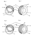
- the main body 14 is according to the embodiments almost bottomless. From the bottom remains a maximum edge, so centrally there is a large hole.
- the main body 14 thus consists essentially only of a hollow cylindrical Wall with an inner cross section and an outer cross section.
- the inner cross section is in the in FIG. 1 and FIG. 3 illustrated embodiments in the axial direction stepwise smaller. In the embodiments of the FIGS. 2 and 4 the inner cross section is constant in the axial direction.
- a toothing 20, 200 is applied on an outer periphery 16 of the main body 14 and the wall.
- the toothing 20, 200 preferably runs parallel to the axis of the main body 14.
- the teeth 20, 200 conceivable. It must be made possible by this only a power transmission to a corresponding belt.
- it is a toothed belt with teeth perpendicular to its length.
- a roughening of the surface of the base body 14 would be sufficient.
- the toothing 20, 200 of the main body 14 is in the first two embodiments ( Fig. 1, Fig. 2 ) introduced into the base body 14 by machining.
- the toothing 20, 200 can for this purpose be introduced particularly advantageously by hobbing in the base body 14.
- a toothing 200 may be applied by a contoured plastic layer 202 on the outer circumference of the base body 14.
- the toothing 20, 200 is delimited axially on both end faces 22, 24 of the main body 14 by a flanged wheel 30, 30 ', 30 "by the completion of the toothing 20, 200 on the end faces 22, 24 of the base body 14 with the flanged wheels 30 , 30 ', 30 "ensures a secure guidance of a toothed belt.
- the toothed belt is secured by the protruding flanges 30, 30 ', 30 "from slipping.
- the flanged wheel 30, 30 ', 30 has a larger outer diameter than the base body 14 in order to allow a secure guidance of the belt, various inner diameters being possible for the flange 30, 30', 30".
- the inner diameter of the flanged wheel 30 can be approximately equal to the outer circumference of the main body 14, if the flanged wheel 30 is to be provided, for example, next to the toothing 20, 200 at the edge of the toothed belt wheel 10, 100.
- the flanged wheel 30 would thus expand an end face 22, 24 of the base body 14 radially outwardly when it is placed flush. This is in the first embodiment ( Fig. 1 ).
- the teeth 20, 200 may extend over the entire width of the base body 14. This would be particularly important if the teeth 20, 200 would be raised radially outwardly beyond the outer circumference of the main body 14, as in the third and fourth embodiments ( FIGS. 3 and 4 ) is executed.
- An inner diameter of the flanged wheel 30 approximately equal to the outer circumference of the main body 14 and a placement of the flanged wheel 30 in addition to the teeth 20, 200 namely enforce a corresponding consideration, possibly post-processing during application of the toothing.
- a third possibility for the selection of the inner diameter of the Borusion 30 " is in the fourth embodiment ( Fig. 4 ) of a toothed belt wheel 100 'executed.
- the inner diameter of the flange 30 " is smaller here than the inner diameter of the base body 14.
- the flanged wheels 30, 30 ', 30 also have the task of reinforcing the base body 14. They can be attached either by welding, by pressing or by caulking on the base body 14. For this purpose, the flanged wheels 30, 30' should be used. It is particularly advantageous, alternatively to the abovementioned variants, to spray an edge disc 30, 30 ', 30 "made of plastic on an end face 22, 24 of the main body 14 ,
- one or both flanged wheels 30, 30 ', 30' ' is applied to the base body 14 together with the contoured plastic layer 202 in one production step.
- the application of the existing plastic toothing with simultaneously integrally formed flange or flanged wheels can, for example. done by plastic injection.
- both flanged wheels When machined in the deep-drawn metal part toothing 20, 200 in the timing pulley 10 both flanged wheels must 30, 30 ', 30 "may be formed as separate parts, namely that the machining step makes it necessary for an outlet to be provided beyond the end faces 22, 24 for the milling cutter milling the toothing.
- an embodiment of the flanged wheel 30, 30 ', 30 is possible, in which the flanged wheel 30, 30', 30" is clipped into the contoured plastic layer 202.
- Another attachment of the flanged wheel 30, 30 ', 30 is given, for example, by positive locking of the flanged wheel 30, 30', 30" with the contoured plastic layer 202.
- Connections between parts made of plastic 30, 30 ', 30' ', 202 may alternatively be carried out by welding with ultrasound or with laser.
- the toothed belt 10, 100 is to transmit a force from an output shaft of a drive to a toothed belt.
- the timing pulley 10, 100 must therefore be driven directly or indirectly from the output shaft.
- the base body 14 is provided with driving cams 18, wherein the driving cams 18 protrude radially inward in the hole of the main body.
- FIGS. 1 and 3 is in each case such a driving sock 18 to see.
- the driving cams 18 can engage in corresponding contours of the output shaft of the drive.
- Frictional connections between the toothed belt 10, 100 and output shaft are alternatively executable by interference fit or other compounds.
- FIG. 7 Another in FIG. 7 illustrated embodiment of a flanged wheel 30 '''goes beyond the embodiments of the FIGS. 1 to 4 insofar as that the flanged wheel 30 '''a pot-shaped or bell-shaped base body 14 with teeth 20, 200 provides.
- Two such flanged wheels 30 '''together in coaxial arrangement form a toothed belt wheel, when their base bodies are connected to each other facing each other, so that the flanged wheels 30''' are arranged facing away from each other.
- a method for producing a toothed belt wheel 10, 10 ' comprises, as a first step, the deep-drawing of the pot-shaped or bell-shaped main body 14 made of a metal.
- a second step is the cutting introduction of the toothing 20 into the base body 14 on its outer circumference 16.
- two flanged wheels 30, 30 ', 30 are provided on the end faces 20, 24 of the base body 14.
- at least one of the flanged wheels 30, 30 ', 30 is fastened to an end face 22, 24 of the base body 14.
- a method for producing a toothed belt wheel 100, 100 ', as indicated for example with the exemplary embodiments 3 and 4, also includes deep-drawing as the first method step the pot-shaped or bell-shaped base body 14 made of a metal.
- the toothing 200 made of plastic is applied to the base body on its outer circumference 16.
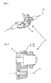
- a power steering drive 60 is in the FIGS. 5 and 6 shown. In Figure 5 it is clear that the power steering drive 60 is executed paraxial.
- a drive housing 62 of the power steering drive 60 is arranged parallel to a power steering axis 64.
- the drive housing 62 includes the toothed belt wheel, which causes a force transmission to the coaxial power steering axis 64 via the toothed belt.
Landscapes
- Engineering & Computer Science (AREA)
- General Engineering & Computer Science (AREA)
- Mechanical Engineering (AREA)
- Pulleys (AREA)
- Devices For Conveying Motion By Means Of Endless Flexible Members (AREA)
Applications Claiming Priority (1)
| Application Number | Priority Date | Filing Date | Title |
|---|---|---|---|
| DE102008025077A DE102008025077A1 (de) | 2008-05-26 | 2008-05-26 | Zahnriemenrad für einen Zahnriemenantrieb |
Publications (2)
| Publication Number | Publication Date |
|---|---|
| EP2128496A2 true EP2128496A2 (fr) | 2009-12-02 |
| EP2128496A3 EP2128496A3 (fr) | 2009-12-16 |
Family
ID=40941966
Family Applications (1)
| Application Number | Title | Priority Date | Filing Date |
|---|---|---|---|
| EP09006899A Withdrawn EP2128496A3 (fr) | 2008-05-26 | 2009-05-22 | Roue à courroie dentée pour un entraînement de courroie dentée |
Country Status (4)
| Country | Link |
|---|---|
| US (1) | US20090291792A1 (fr) |
| EP (1) | EP2128496A3 (fr) |
| CN (1) | CN101592216A (fr) |
| DE (1) | DE102008025077A1 (fr) |
Cited By (6)
| Publication number | Priority date | Publication date | Assignee | Title |
|---|---|---|---|---|
| DE102013112542A1 (de) | 2013-11-14 | 2015-05-21 | Trw Automotive Gmbh | Getriebebaugruppe für eine elektromechanische Servolenkung |
| DE102014201565A1 (de) | 2014-01-29 | 2015-07-30 | Volkswagen Aktiengesellschaft | Bordscheibe für einen Riementrieb, Verfahren zur Herstellung einer solchen Bordscheibe, Verfahren zur Befestigung einer Bordscheibe an einem Riementrieb sowie Anordnung einer Bordscheibe an einem Riementrieb |
| DE102015111243A1 (de) | 2015-07-10 | 2017-01-12 | Trw Automotive Gmbh | Fahrzeug-Lenksystem |
| AT518781A4 (de) * | 2016-12-19 | 2018-01-15 | Miba Sinter Austria Gmbh | Riemenrad |
| EP3385572A1 (fr) * | 2017-04-04 | 2018-10-10 | Jtekt Corporation | Système de direction |
| DE102022203995B3 (de) | 2022-04-26 | 2023-10-12 | Zf Friedrichshafen Ag | Riemenrad mit einem Tragring und Verfahren zum Herstellen eines Riemenrads |
Families Citing this family (6)
| Publication number | Priority date | Publication date | Assignee | Title |
|---|---|---|---|---|
| DE102010003105A1 (de) * | 2010-03-22 | 2011-09-22 | Zf Lenksysteme Gmbh | Servolenkung |
| DE102013103493A1 (de) * | 2013-04-08 | 2014-10-23 | Trw Automotive Gmbh | Riemenscheibe und Getriebemutter mit einer solchen Riemenscheibe |
| DE102013216916B4 (de) | 2013-08-26 | 2023-06-01 | Volkswagen Aktiengesellschaft | Zahnriemenrad, Lenkung eines Kraftfahrzeuges mit einem solchen Zahnriemenrad sowie Verfahren zur Montage eines Zahnriemens |
| CN105333103B (zh) * | 2015-11-18 | 2019-04-23 | 杭州禾呈科技股份有限公司 | 一种两级同轴多楔式高精度旋压皮带轮及其制造方法 |
| DE102018201630B4 (de) | 2018-02-02 | 2023-01-19 | Zf Friedrichshafen Ag | Riemenrad für einen Zahnriementrieb einer steer-by-wire-Lenkung und Verfahren zur Herstellung des Riemenrades sowie Verwendung des Riemenrades |
| DE102018209536B4 (de) | 2018-06-14 | 2024-08-01 | Bayerische Motoren Werke Aktiengesellschaft | Zahnriemenrad |
Citations (8)
| Publication number | Priority date | Publication date | Assignee | Title |
|---|---|---|---|---|
| DE29715257U1 (de) | 1997-08-26 | 1997-12-04 | Atlas Copco Electric Tools GmbH, 71364 Winnenden | Mitnahmevorrichtung |
| DE10237557A1 (de) | 2002-08-16 | 2004-02-26 | Alfred Kärcher Gmbh & Co. Kg | Taumelscheibenpumpe, insbesondere für Hochdruckreinigungsgeräte |
| DE69723523T2 (de) | 1996-10-08 | 2004-03-04 | Scambia Industrial Developments Ag | Wagenheber und Verfahren zur Fertigung derselben |
| DE10352256A1 (de) | 2003-11-08 | 2005-06-09 | Ina-Schaeffler Kg | Wälzkörpergewindetrieb |
| DE102004038681A1 (de) | 2004-08-10 | 2006-06-01 | Schaeffler Kg | Elektromotorischer Nockenwellenversteller |
| DE102005006673A1 (de) | 2004-11-19 | 2006-06-08 | Rempel Stanztechnik Gmbh & Co.Kg | Verfahren zur Herstellung eines Metallteiles eines Kunststoff-Metall-Verbundteiles und ein nach dem Verfahren hergestelltes Metallteil |
| DE102005061481A1 (de) | 2005-12-22 | 2007-07-05 | Schaeffler Kg | Schaltvorrichtung |
| DE102006059946A1 (de) | 2005-12-22 | 2007-07-05 | Volkswagen Ag | Zahnriemenrad |
Family Cites Families (17)
| Publication number | Priority date | Publication date | Assignee | Title |
|---|---|---|---|---|
| DE7301225U (de) * | 1973-04-26 | Winkelmann & Pannhoff Gmbh | Zahnriemenscheibe, insbesondere fur Antriebe mit geringer Drehmomentuber tragung | |
| US2724975A (en) * | 1952-10-15 | 1955-11-29 | Niles Bement Pond Co | Pressed steel pulley |
| DE2314000A1 (de) * | 1973-03-21 | 1974-09-26 | Davall Gear Company Ltd | Rad od. dgl |
| IT1116319B (it) * | 1977-11-02 | 1986-02-10 | Iao Industrie Riunite Spa | Puleggia stampata da lamiera per trasmissioni a cinghia dentata |
| DE2833458C3 (de) * | 1978-07-29 | 1981-01-29 | A. Friedr. Flender Gmbh & Co Kg, 4290 Bocholt | Riemenscheibe mit Bordscheibe |
| JPS5768238A (en) * | 1980-10-09 | 1982-04-26 | Honda Motor Co Ltd | Manufacture of tooth form member transmission |
| DD227365A1 (de) * | 1984-10-15 | 1985-09-18 | Zentralinstitut Schweiss | Verfahren zum herstellen von elastischen raedern |
| DE8909052U1 (de) * | 1989-07-26 | 1989-09-07 | Gebrüder Sulzer AG, Winterthur | Zahnriemenscheibe |
| DE4219108C1 (de) * | 1992-06-11 | 1994-03-03 | Freudenberg Carl Fa | Riemenscheibe |
| JP2001276939A (ja) * | 2000-03-29 | 2001-10-09 | Tsubakimoto Chain Co | かしめローラ及びかしめローラによりかしめ加工されるフランジ付き焼結製プーリ |
| JP2004301208A (ja) * | 2003-03-31 | 2004-10-28 | Koshin Kogyo Kk | 歯車およびその製造方法 |
| DE102005041046A1 (de) * | 2004-08-31 | 2006-04-06 | Denso Corp., Kariya | Leistungsübertragungsvorrichtung zur Verwendung mit einem Verbrennungsmotor und Verfahren zur Herstellung einer Riemenscheibeneinheit |
| DE102004058963A1 (de) * | 2004-12-08 | 2006-06-14 | Schaeffler Kg | Zahnriemenscheibe |
| DE102005018581A1 (de) * | 2005-04-21 | 2006-10-26 | Volkswagen Ag | Zahnriemenscheibe mit einer an dieser befestigten Bordscheibe |
| JP2007160439A (ja) * | 2005-12-12 | 2007-06-28 | Gates Unitta Asia Co | 歯付プーリの製造方法 |
| AT506562B1 (de) * | 2007-04-30 | 2011-05-15 | Miba Sinter Austria Gmbh | Zahnriemenrad |
| DE102007023364A1 (de) * | 2007-05-18 | 2008-11-20 | Schaeffler Kg | Riemenscheibe |
-
2008
- 2008-05-26 DE DE102008025077A patent/DE102008025077A1/de not_active Withdrawn
-
2009
- 2009-04-22 US US12/428,158 patent/US20090291792A1/en not_active Abandoned
- 2009-05-13 CN CNA2009101409306A patent/CN101592216A/zh active Pending
- 2009-05-22 EP EP09006899A patent/EP2128496A3/fr not_active Withdrawn
Patent Citations (8)
| Publication number | Priority date | Publication date | Assignee | Title |
|---|---|---|---|---|
| DE69723523T2 (de) | 1996-10-08 | 2004-03-04 | Scambia Industrial Developments Ag | Wagenheber und Verfahren zur Fertigung derselben |
| DE29715257U1 (de) | 1997-08-26 | 1997-12-04 | Atlas Copco Electric Tools GmbH, 71364 Winnenden | Mitnahmevorrichtung |
| DE10237557A1 (de) | 2002-08-16 | 2004-02-26 | Alfred Kärcher Gmbh & Co. Kg | Taumelscheibenpumpe, insbesondere für Hochdruckreinigungsgeräte |
| DE10352256A1 (de) | 2003-11-08 | 2005-06-09 | Ina-Schaeffler Kg | Wälzkörpergewindetrieb |
| DE102004038681A1 (de) | 2004-08-10 | 2006-06-01 | Schaeffler Kg | Elektromotorischer Nockenwellenversteller |
| DE102005006673A1 (de) | 2004-11-19 | 2006-06-08 | Rempel Stanztechnik Gmbh & Co.Kg | Verfahren zur Herstellung eines Metallteiles eines Kunststoff-Metall-Verbundteiles und ein nach dem Verfahren hergestelltes Metallteil |
| DE102005061481A1 (de) | 2005-12-22 | 2007-07-05 | Schaeffler Kg | Schaltvorrichtung |
| DE102006059946A1 (de) | 2005-12-22 | 2007-07-05 | Volkswagen Ag | Zahnriemenrad |
Cited By (11)
| Publication number | Priority date | Publication date | Assignee | Title |
|---|---|---|---|---|
| DE102013112542A1 (de) | 2013-11-14 | 2015-05-21 | Trw Automotive Gmbh | Getriebebaugruppe für eine elektromechanische Servolenkung |
| WO2015071057A1 (fr) * | 2013-11-14 | 2015-05-21 | Trw Automotive Gmbh | Ensemble de transmission pour direction assistée électromécanique |
| DE102014201565A1 (de) | 2014-01-29 | 2015-07-30 | Volkswagen Aktiengesellschaft | Bordscheibe für einen Riementrieb, Verfahren zur Herstellung einer solchen Bordscheibe, Verfahren zur Befestigung einer Bordscheibe an einem Riementrieb sowie Anordnung einer Bordscheibe an einem Riementrieb |
| DE102015111243A1 (de) | 2015-07-10 | 2017-01-12 | Trw Automotive Gmbh | Fahrzeug-Lenksystem |
| WO2017009252A1 (fr) * | 2015-07-10 | 2017-01-19 | Trw Automotive Gmbh | Système de direction de véhicule |
| AT518781A4 (de) * | 2016-12-19 | 2018-01-15 | Miba Sinter Austria Gmbh | Riemenrad |
| AT518781B1 (de) * | 2016-12-19 | 2018-01-15 | Miba Sinter Austria Gmbh | Riemenrad |
| DE102017011502A1 (de) | 2016-12-19 | 2018-06-21 | Miba Sinter Austria Gmbh | Riemenrad |
| EP3385572A1 (fr) * | 2017-04-04 | 2018-10-10 | Jtekt Corporation | Système de direction |
| US10661824B2 (en) | 2017-04-04 | 2020-05-26 | Jtekt Corporation | Steering system |
| DE102022203995B3 (de) | 2022-04-26 | 2023-10-12 | Zf Friedrichshafen Ag | Riemenrad mit einem Tragring und Verfahren zum Herstellen eines Riemenrads |
Also Published As
| Publication number | Publication date |
|---|---|
| US20090291792A1 (en) | 2009-11-26 |
| CN101592216A (zh) | 2009-12-02 |
| EP2128496A3 (fr) | 2009-12-16 |
| DE102008025077A1 (de) | 2009-12-10 |
Similar Documents
| Publication | Publication Date | Title |
|---|---|---|
| DE102008025077A1 (de) | Zahnriemenrad für einen Zahnriemenantrieb | |
| EP2707614B1 (fr) | Liaison par emboîtement pour la liaison solidaire en rotation de deux pièces et son procédé | |
| EP2245339B1 (fr) | Pièce à denture interne et externe ainsi que procédé pour produire cette pièce | |
| EP2376810B1 (fr) | Pièce moulée,porte-satellites,arbre creux,transmission planetaire | |
| WO2005015056A1 (fr) | Porte-satellites pour boites de vitesses | |
| EP3409392A1 (fr) | Procédé de fabrication de pièces estampées | |
| DE102014208003A1 (de) | Planetenträger für ein Planetengetriebe aus verschweißten Teilen | |
| EP3722641A1 (fr) | Agencement de porte satellites d'un engrenage épicycloïdal, en particulier un engrenage épicycloïdal d'un entraînement de porte latérale, ainsi que procédé de fabrication d'un tel agencement de porte satellites | |
| DE102007026605A1 (de) | Kugelgewindetrieb | |
| DE102007028259A1 (de) | Verbindung zwischen zwei einen runden Querschnitt aufweisenden Bauteilen eines Getriebes zur Aufnahme von Axialkräften | |
| DE102017222891A1 (de) | Blech-Lamellenträger sowie Verfahren zu dessen Drehzahlfestigkeitserhöhung | |
| EP2495468A2 (fr) | Train épicycloïdal doté d'une liaison arbre-moyeu | |
| EP3938681B1 (fr) | Différentiel | |
| DE102021111620A1 (de) | Planetenträger und Verbindungsverfahren für Teile des mehrteiligen Planetenträgers sowie Planetengetriebe | |
| DE102015213725A1 (de) | Aus Segmenten zusammengesetzter Planetenträger | |
| DE10317506B4 (de) | Verfahren zum Herstellen eines hohlen Werkstücks und nach dem Verfahren hergestelltes hohles Werkstück | |
| DE102019129724A1 (de) | Planetenträger mit segmentierter Steckverzahnung und integrierten Distanzelementen, Bausatz aus Planetengetriebe mit Welle und Verfahren zum Herstellen einer Planetenträgersteckverzahnung | |
| DE102012202446A1 (de) | Getrieberad, insbesondere Sonnenrad für ein Differenzialgetriebe | |
| WO2017063813A1 (fr) | Couronne à denture intérieure et à denture frontale, ainsi que procédé de fabrication associé et boîte de vitesses dotée d'une telle couronne | |
| DE102020201889A1 (de) | Ritzel für einen Fahrrad-Antrieb | |
| WO2007128359A1 (fr) | Procédé de fabrication d'un élément de transmission | |
| DE102005053989B4 (de) | Verfahren zur Herstellung eines Kupplungskörpers | |
| WO2008034711A2 (fr) | Liaison d'un premier élément cylindrique avec un second élément cylindrique et procédé pour le montage du premier et du second élément | |
| DE102008000445A1 (de) | Radantrieb, insbesondere für Kraftfahrzeuge | |
| DE102012202455A1 (de) | Differenzialbaugruppe mit einer Kunststoffverbindungsmethode und Montage eines Planetenträgers |
Legal Events
| Date | Code | Title | Description |
|---|---|---|---|
| PUAI | Public reference made under article 153(3) epc to a published international application that has entered the european phase |
Free format text: ORIGINAL CODE: 0009012 |
|
| PUAL | Search report despatched |
Free format text: ORIGINAL CODE: 0009013 |
|
| AK | Designated contracting states |
Kind code of ref document: A2 Designated state(s): AT BE BG CH CY CZ DE DK EE ES FI FR GB GR HR HU IE IS IT LI LT LU LV MC MK MT NL NO PL PT RO SE SI SK TR |
|
| AK | Designated contracting states |
Kind code of ref document: A3 Designated state(s): AT BE BG CH CY CZ DE DK EE ES FI FR GB GR HR HU IE IS IT LI LT LU LV MC MK MT NL NO PL PT RO SE SI SK TR |
|
| RIC1 | Information provided on ipc code assigned before grant |
Ipc: F16H 55/36 20060101ALN20091112BHEP Ipc: F16H 55/17 20060101AFI20091112BHEP Ipc: F16H 55/48 20060101ALN20091112BHEP |
|
| 17P | Request for examination filed |
Effective date: 20100304 |
|
| 17Q | First examination report despatched |
Effective date: 20100610 |
|
| STAA | Information on the status of an ep patent application or granted ep patent |
Free format text: STATUS: THE APPLICATION IS DEEMED TO BE WITHDRAWN |
|
| 18D | Application deemed to be withdrawn |
Effective date: 20101228 |