EP2129272B1 - Lot de pose pour la réalisation de finitions murales ou au sol entre des objets posés et une paroi de finition ou un sol - Google Patents
Lot de pose pour la réalisation de finitions murales ou au sol entre des objets posés et une paroi de finition ou un sol Download PDFInfo
- Publication number
- EP2129272B1 EP2129272B1 EP07847373.3A EP07847373A EP2129272B1 EP 2129272 B1 EP2129272 B1 EP 2129272B1 EP 07847373 A EP07847373 A EP 07847373A EP 2129272 B1 EP2129272 B1 EP 2129272B1
- Authority
- EP
- European Patent Office
- Prior art keywords
- strip
- installation kit
- tape
- wall
- floor
- Prior art date
- Legal status (The legal status is an assumption and is not a legal conclusion. Google has not performed a legal analysis and makes no representation as to the accuracy of the status listed.)
- Active
Links
Images

Classifications
-
- A—HUMAN NECESSITIES
- A47—FURNITURE; DOMESTIC ARTICLES OR APPLIANCES; COFFEE MILLS; SPICE MILLS; SUCTION CLEANERS IN GENERAL
- A47K—SANITARY EQUIPMENT; ACCESSORIES THEREFOR, e.g. TOILET ACCESSORIES
- A47K3/00—Baths; Showers; Appurtenances therefor
- A47K3/008—Sealing between wall and bathtub or shower tray
-
- A—HUMAN NECESSITIES
- A47—FURNITURE; DOMESTIC ARTICLES OR APPLIANCES; COFFEE MILLS; SPICE MILLS; SUCTION CLEANERS IN GENERAL
- A47B—TABLES; DESKS; OFFICE FURNITURE; CABINETS; DRAWERS; GENERAL DETAILS OF FURNITURE
- A47B77/00—Kitchen cabinets
- A47B77/02—General layout, e.g. relative arrangement of compartments, working surface or surfaces, supports for apparatus
- A47B77/022—Work tops
Definitions
- the invention relates to a kit for the production of watertight wall and floor finishes after the installation or installation of baths, shower trays, kitchen appliances, work desks, etc., especially on lightweight walls and drywall, such as wood fiber and plasterboard after the preamble of claim 1.
- Patent CH 690162 discloses a kit with all the features of the preamble of claim 1.
- the invention has the object to provide a kit for the production of watertight wall connections and / or bottom finishes for installation items (bathtubs, shower trays, kitchen countertops, and the like), with a simple and easy adaptation to the present on site installation conditions is possible on site ,
- the sealing tape in addition to e.g. T-shaped, flexible Zargenband a separate from the installation item sealing tape provided for attachment to the end wall.
- This sealing tape is here designed so that it overlaps in the installed state with a water-impermeable overlap strip an upper strip of the Zargenbandes.
- the sealing tape comprises a so-called penetration strip, which is connected by coating or rolling over with a coating liquid close to the underlying end wall.
- the frame can be mounted on site on the sides of the installation object, which come to rest on an end wall or floor and thus require a degree. Then the fixture is placed on the end wall or floor and the sealing tape is fixed to the end wall or floor so that the waterproof overlap strip overlaps the top strip of the frame tape.
- the penetration strip and the overlying area of the end wall or the floor is coated or rolled over with the coating liquid.
- the installation items for example, a bath or shower tray, so for example with the T-shaped, flexible frame together with the sealing tape with a few simple steps a clean and dense wall or bottom closure are created.
- the T-shaped, flexible frame instead of the T-shaped, flexible frame but also simpler frames can be used. But it can also rigid frames (eg sheet metal or metal foil) in Used in connection with the invention.
- the lightweight wall or a corresponding floor area is thus reliably protected from moisture.
- the sealing tape is at least partially made of flexible material. This allows the sealing band to move the tub, e.g. due to subsidence due to shrinkage or warping of the screeds or underlay floors give, without the ceramic tiles forming the wall covering (tiles) are damaged. The tightness is not affected when yielding such an elastic material.
- a sealing tape according to the invention can be made at least partially of plastic, of textile materials and / or metal foils and / or sheet metal.
- the choice of material for such a sealing tape depends on the particular application and can be adjusted accordingly.
- the sealing tape can preferably be cut on site and thus adapted in every situation.
- the sealing tape together with Zargenband for example, a T-shaped flexible or rigid Zargenband
- prefabricated kit prefabricated
- gluing For the fixation of the sealing tape on the end wall or on the floor gluing is preferred. Care must be taken that the sealing tape lies as flat as possible against the corresponding surface of the end wall or the floor. Instead of gluing the sealing tape but can also be screwed, riveted, welded, vulcanized, stapled or fixed with an adhesive strip or with liquid plastic.
- the sealing tape In the case of an adhesive fixation of the sealing tape, the use of a self-adhesive tape is recommended. In this way, the sealing tape is particularly easy to handle. It can be fixed to the installation site by pressing firmly on the end wall or on the floor. However, it is also conceivable other adhesive options, for example by means of an adhesive, i. with a mass applied to a back of the sealing tape or directly to the end wall or floor.
- This fixation is mainly used to fix the sealing tape to the end wall, until it is connected by the coating liquid to be applied tightly with the underlying end wall.
- the sealing tape or at least one upper region of the sealing tape can already be made ex works so that it is tight in itself.
- the frame strap comprises a penetration strip.
- the frame strap may also have one or two strips, e.g. of thick, soft material (preferably foam) to provide sound isolation between a bathtub or a shower and the wall or floor.
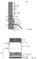
- a first embodiment of the invention is in Fig. 1A and 1B shown.
- a kit 20 for the production of wall closures between installation items such as a bathtub 2, or a shower tray or other sanitary or kitchen utensil and a closure wall. 1 for use.
- the kit 20 includes a separate from the installation item 2 elongated Zargenband 6 for attachment between the installation object 2 and the end wall 1.
- the frame strip 6 in the embodiment shown in the assembled state has an approximately T-shaped cross-section with an angled upper strip 6.1 (in the Fig.
- the roof area in the assembled state extends vertically and parallel to the end wall 1 and its legs (as the foot of the T's T-shaped cross section, which is perpendicular to the roof area) with a horizontal tub Abbordungs area 2.2 of the bathtub. 2 is glued.
- the frame strip 6 comprises a lower strip 6.2, which is more or less an extension of the roof area of the T and runs parallel to the end wall 1.
- the lower strip 6.2 of the Zargenbandes 6 has at least one sealingly attached to the installation object 2 surface.
- Fig. 1A is indicated by a dark gray strip 6.3 between the side facing away from the end wall 1 surface of the lower strip 6.2 and a parallel to the end wall 1 extending vertical surface 2.1 of the bathtub Abbordung that there is an adhesive.
- an adhesive surface is present on the underside of the leg of the upper angled strip 6.1, ie on the horizontal in the example shown underside, which rests on a horizontal surface 2.2 of the bathtub Abbordung.
- the Zargenband 6 further has a connected to the legs of the upper angled strip 6.1 back-feeding section 8, which runs parallel to the horizontal surface 2.2 of the bathtub Abbordung in the example shown.
- the kit 20 additionally comprises a separate from the installation item 2 elongated sealing tape 10 for attachment to the end wall 1.
- This sealing tape 10 has a water-impermeable overlap strip 10.2, the merges into a penetration strip 10.1.
- the overlap strip 10.2 and the penetration strip 10.1 are in the FIGS. 1A to 3 to recognize.
- the sealing tape 10 can be fixed to the end wall 1 after installation of the frame strip 6 (or another frame, such as a rigid frame) on the bath 2 and after placing the bathtub 2 against the end wall 1. Care is taken to ensure that the water-impermeable overlap strip 10.2 partially overlaps the roof area of the upper strip 6.1 of the T-shaped frame 6, as in FIG Fig. 1A and Fig. 1B indicated.
- the penetration strip 10.1 lies flat against the end wall 1 and is covered and impregnated with a coating liquid 13 in this particular embodiment.
- the area 21 of the penetration strip 10.1 is in Fig. 1A illustrates the penetration through a black and white dashed area.
- Fig. 1B shows area 21 as a diamond-shaped area.
- the sealing tape 10 on a back 11 which rests in the assembled state on the end wall 1, an adhesive surface 10.3 or an adhesive in order to fix the sealing tape 10 at least temporarily on the end wall 1 can.
- the entire handling is simplified, since the sealing tape 10 can be easily covered or rolled over after fixing with the coating liquid 13.
- the sealing tape 10 and / or the frame tape 6 may also be temporarily attached to the wall or floor with tape or other fasteners (such as screws, nails, rivets, glue, etc.) to bridge the time until then eg tiles are laid.
- tape or other fasteners such as screws, nails, rivets, glue, etc.
- the sealing tape 10 and / or the frame tape 6 may also be provided with means (e.g., sealing strips) to provide a tight connection to a wall or floor.
- means e.g., sealing strips
- the frame strip 6 may have an adhesive surface or adhesive on the upper strip 6.1 in order to be able to fix the sealing strip 10 at least temporarily to the frame strip 6.
- the kit additionally comprises the suitable brushable or rollable coating liquid 13, which is designed so that it penetrates after fixing the sealing strip 10 on the end wall 1 by sweeping or rolling over the fürdringungsstieifens 10.1 and a sealing connection to the end wall 1 or the floor generated.
- the coating liquid 13 is designed to protect the lightweight wall 1 or the floor from ingress of water.
- the coating liquid 13 fills the pores of the wall 1 or the floor and seals the wall 1 or the floor with a water-repellent protective layer.
- the coating liquid 13 used is a combination of a primer and a paintable liquid film.
- the overlap strip 10.2 is dimensioned so that it overlaps the upper strip 6.1 of the frame strip 6 from above in the assembled state, so that moisture, which runs down the end wall 1, over the fürdringungsstsammlung 10.1 and the overlap strip 10.2 from the end wall 1 away on a side facing away from the end wall 1 outside of the upper strip 6.1 passes.
- the back-feeding section 8 serves, on the one hand, for soundproofing between a wall covering plate 3 (for example a tile or a glass plate) and the rim 2.
- the back-feeding section 8 additionally serves as the basis for a sealing joint and as a spacer for the wall covering plates 3 during their laying.
- the back-feeding section 8 may have an extension which, as a protective strip, protects the tub rim 2 against contamination and damage during assembly. This extension of the back-feeding section 8 can be removed at a pre-perforated position after laying the wall covering plates 3.
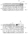
- FIGS. 2 and 3 are sub-steps of the production of a wall termination according to the invention can be seen, wherein Fig. 2 a first embodiment and Fig. 3 shows a second embodiment of the invention. Similarly, a conclusion can be made against a floor.
- the frame strip 6 is glued to the vertical bows 2.1.
- the back-feeding portion 8 is placed or glued with a part of the upper strip 6.1 on the horizontal tub edge 2.2.
- the adhesive bond of a part of the back-feeding section 8 should not be too tight here, if the front part of the back-feeding section 8 is to serve as a protective strip and should later be cut off at the aforementioned pre-perforated point.
- the sealing tape 10 is fixed to the end wall 1. This can be done by peeling off a protective film 10.4 on the rear side 11 of the sealing tape 10 in order to expose an adhesive strip 10.3.
- Fig. 2 are the later to be swept or penetrated fürdringungsstsammlung 10.1 and the overlap strip 10.2 indicated.
- the Penetration tabs 10.1 and overlap tabs 10.2 may both be made of the same material, with at least the overlap tab 10.2 being specifically impregnated to prevent passage of water.
- the penetration strip 10.1 is deliberately unimpregnated in a preferred embodiment, so that the coating liquid 13 reaches through the penetration strip 10.1 through the underlying wall 1 and connects to it.
- Particularly preferred is a penetration strip 10.1, which is porous, absorbent or even holey (for example, reticulated).
- Fig. 3 an embodiment is shown in which the penetration strip 10.1 is in the form of a porous gauze or other porous strip.
- the coating with the coating liquid 13 is in Fig. 3 indicated by a brush 12.
- the wall cover plates are attached.
- the optional front portion of the back-feeding section 8 can be torn off and pulled away.
- the back-feeding section 8 now serves as the basis for a sealing joint as a primary seal, for example of silicone material.
- FIG. 4 Another embodiment of the invention is in Fig. 4 shown. It comes from the installation item 2 separate, elongated Zargenband 6 is used, which is arranged between the installation object 2 and the end wall 1.
- the frame strip 6 In the mounted state, the frame strip 6 has the parallel to the end wall 1 extending lower strip 6.2, which has a sealingly attached to the installation object 2 to be flat.
- an adhesive strip or adhesive material can be used in Fig. 4 marked as dark gray strip 6.3.
- the frame tape 6 can be glued to the tub 2 and there is no water along the tub-Abbordungs-area 2.2 of the bathtub 2 run backwards between frame and wall 1.
- the elongate sealing strip 10 separate from the installation object 2 is used, which can be attached to the end wall 1, as shown schematically in FIG Fig. 4 indicated.
- This sealing tape 10 has the water-impermeable overlap strip 10.2, which merges into the upper area mentioned in the penetration strips 10.1.
- This penetration strip 10.1 is in the in Fig. 4 shown embodiment, which means that even the upper portion of the sealing tape 10 does not pass water.
- the fürdringungsstAIN 10.1 may be glued to the wall 1, screwed, welded, festgetackert or riveted.
- a back-feeding portion 8 is attached, which extends at right angles.
- This back-feeding section 8 can be glued to the horizontal region 2.2 of Abbordung the bathtub 2.
- the tiles 3 are then bonded to the wall 1 and the top of the sealing tape 10 with a conventional tile adhesive not shown in the figures.
- Fig. 4 It is shown that the bottom tile 3 gets up or sits on the back-feeding section 8. If you now tear off the back-feeding section 8 in the region of a perforation 8.1, then a piece of the back-feeding section 8 remains under the tile 3.
- the result is a kind of fillet, which can be filled with a joint material (eg silicone).
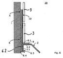
- Fig. 5 Another embodiment of the invention is in Fig. 5 shown. It comes from the installation item 2 separate, elongated Zargenband 6 is used, which is arranged between the installation object 2 and the end wall 1.
- This Zargenband 6 can be rigid or flexible.
- the frame strip 6 is glued in the area designated 6.3 against the installation object 2, where it ensures a watertight Connection.
- the designated 6.2 lower strip of the Zargenbandes 6 extends in height further upwards than in the other embodiments.
- the in Fig. 5 X is designated, the Zargenband 6 may have a fürdringungsstMail, which can be treated as in the sealing strip.
- the Zargenband 6 can also be fixed with the other means mentioned on the wall 1 or on a floor.
- the sealing strip 10 extends parallel to the frame strip 6. Either the frame strip 6 and the sealing strip 10 can be fastened together in the region X, or the sealing strip 10 is fastened, for example by adhering the tiles 3. As with the in Fig. 4 shown embodiment is also in the embodiment according to Fig. 5 the back-feeding section 8 is fastened to the sealing strip 10 and not to the frame strip 6.
- the frame band 6 and the sealing tape 10 are joined together, i.
- the two elements are not supplied individually, to be connected to each other only on site during installation.
- insulating strip 6.4 eg a foam strip
- This insulating strip 6.4 can be arranged on the outside (ie on the wall side) or on the inside (eg between the lower strip 6.2 and the strip 6.3).
- the installation kit 20 comprising at least the frame strip 6 and the sealing strip 10, allows a quick, trouble-free and reliable sealing of all possible sanitary and kitchen installations on an end wall.
- This invention is particularly suitable for use in dry construction in kitchens, bathrooms, swimming pools, but also in industrial environments where moisture may be present in Drywall or soils could penetrate.
- All parts can be pre-assembled or individually assembled and / or assembled on site.
Landscapes
- Health & Medical Sciences (AREA)
- Public Health (AREA)
- Epidemiology (AREA)
- General Health & Medical Sciences (AREA)
- Finishing Walls (AREA)
- Building Environments (AREA)
Claims (12)
- Lot de pose (20) pour la réalisation de finitions murales entre des objets posés (2) et une paroi de finition (1) ou un sol;
où le lot de pose (20) comprend une bande d'encadrement (6) oblongue, séparément de l'objet posé (2), pour être placée entre objet posé (2) et paroi de finition (1) ou sol;
où la bande d'encadrement (6) a dans l'état montée une première bande (6.2) parallèle au paroi de finition (1) ou au sol;
où la première bande (6.2) a une surface pour être fixée étanchée sur l'objet posé (2);
et la bande d'encadrement (6) a une deuxième zone inférieure (6.1) en forme de bande, qui s'étend dans l'état montée parallèlement au paroi de finition (1) ou le sol comme prolongement de la première bande (6.2);- où le lot de pose (20) comprend en outre une bande d'étanchéité allongée (10), séparément de l'objet posé (2), destinée à être fixée à la paroi de finition (1) ou au sol;- où cette bande d'étanchéité (10) a une bande de chevauchement imperméable à l'eau (10.2), qui, dans l'état monté du lot de pose (20) chevauche la deuxième zone (6.1) en forme de bande vers l'objet posé (2) et- que la bande de chevauchement (10.2) passe dans une bande de fixation (10.1) pour la fixation à la paroi de finition (1),caractérisé en ce que- que le lot de pose (20) comprend un segment arrière de remplissage (8), qui à l'état monté, est collé sur un bord de déflexion (2.2) de l'objet posé (2). - Lot de pose (20) conforme à revendication 1, caractérisé en ce que la bande d'encadrement (6) a une bande supérieure (6.1), qui sert comme une deuxième zone en forme de bande, et une première bande (6.2), qui s'étend parallèlement à la paroi de finition (1) comme une bande inférieure, où la bande supérieure (6.1) et la bande inférieure (6.2) ont des surfaces pour la fixation étanchée sur l'objet posé (2), et que le segment arrière de remplissage (8) est partie de la bande d'encadrement (6).
- Lot de pose (20) conforme à revendication 1, caractérisé en ce que le segment arrière de remplissage (8) est partie de la bande d'étanchéité (10).
- Lot de pose (20) conforme à revendication 1, 2 ou 3,
caractérisé en ce que la bande de fixation (10.1) de la bande d'étanchéité (10) est conçu comme une bande de pénétration (10.1). - Lot de pose (20) conforme à revendication 4, caractérisé en ce que la bande d'étanchéité (10) a, sur une côté arrière (11) qui, dans l'état montée, est tangente à la paroi de finition (1), une surface adhésive (10.3) ou un adhésif avec laquelle ou avec lequel la bande d'étanchéité (10) est au moins temporairement fixable sur la paroi de finition (1).
- Lot de pose (20) conforme à revendication 4, caractérisé en ce que- la bande d'étanchéité (10) a, sur une côté arrière (11) qui, dans l'état montée, est tangente à la paroi de finition (1), une surface adhésive ou un adhésifet/ou- la bande d'encadrement (6) a, sur la bande supérieure (6.1) une surface adhésive ou un adhésif avec laquelle ou avec lequel la bande d'étanchéité (10) est au moins temporairement ou permanent étanchée fixable sur la bande d'encadrement (6).
- Lot de pose (20) conforme à revendication 4 ou 5, caractérisé en ce que le lot de pose (20) comprend en outre un liquide de revêtement (13) peindrable ou enroulable, qui est conçu de telle sorte que, après la fixation de la bande d'étanchéité (10) à la paroi de finition (1), on peut le peindre ou enrouler sur la zone de la bande perméable à l'eau (10.1) afin que le liquide de revêtement (13) pénètre la bande perméable (10.1) et produit une liaison étanche au paroi de finition (1).
- Lot de pose (20) conforme à l'une quelconque des revendications précédentes, caractérisé en ce que la bande de chevauchement (10.2) est dimensionnée de telle sorte qu'elle chevauche, à l'état montée, la bande supérieure (6.1) au-dessus, de sorte que humidité ruisselante en bas de la paroi de finition (1) et outre la bande perméable (10.1) et de la bande de chevauchement (10.2), se rend parti de la paroi de finition (1) sur une côté extérieure de la bande d'encadrement (6) opposée à la paroi de finition (1).
- Lot de pose (20) conforme à l'une quelconque des revendications précédentes, caractérisé en ce que la bande d'étanchéité (10) est au moins partiellement réalisée en un matériel flexible.
- Lot de pose (20) conforme à l'une quelconque des revendications précédentes, caractérisé en ce que la bande d'étanchéité (10) est au moins partiellement réalisée en plastique, en matériel textile et/ou en feuille métallique et/ou en tôle métallique.
- Lot de pose (20) conforme à l'une quelconque des revendications précédentes, caractérisé en ce que la bande d'étanchéité (10) et/ou la bande d'encadrement (6) comprend une bande d'isolation (6.4) pour l'isolation acoustique.
- Baignoire ou bac de douche (2), caractérisé en ce qu'il est monté sur une paroi de finition (1) ou sol avec une bande d'encadrement (6) et une bande d'étanchéité (10) conforme à l'une quelconque des revendications précédentes.
Applications Claiming Priority (3)
| Application Number | Priority Date | Filing Date | Title |
|---|---|---|---|
| CH01916/06A CH715223B1 (de) | 2006-11-28 | 2006-11-28 | Einbausatz zur Herstellung von Wandabschlüssen zwischen Einbaugegenständen und einer Abschlusswand. |
| DE202007003943U DE202007003943U1 (de) | 2006-11-28 | 2007-03-17 | Einbausatz zur Herstellung von Wandabschlüssen zwischen Einbaugegenständen und einer Abschlusswand |
| PCT/EP2007/062846 WO2008065096A1 (fr) | 2006-11-28 | 2007-11-27 | Lot de pose pour la réalisation de finitions murales ou au sol entre des objets posés et une paroi de finition ou un sol |
Publications (2)
| Publication Number | Publication Date |
|---|---|
| EP2129272A1 EP2129272A1 (fr) | 2009-12-09 |
| EP2129272B1 true EP2129272B1 (fr) | 2016-03-09 |
Family
ID=38109402
Family Applications (1)
| Application Number | Title | Priority Date | Filing Date |
|---|---|---|---|
| EP07847373.3A Active EP2129272B1 (fr) | 2006-11-28 | 2007-11-27 | Lot de pose pour la réalisation de finitions murales ou au sol entre des objets posés et une paroi de finition ou un sol |
Country Status (4)
| Country | Link |
|---|---|
| EP (1) | EP2129272B1 (fr) |
| CH (1) | CH715223B1 (fr) |
| DE (1) | DE202007003943U1 (fr) |
| WO (1) | WO2008065096A1 (fr) |
Families Citing this family (10)
| Publication number | Priority date | Publication date | Assignee | Title |
|---|---|---|---|---|
| ATE482317T1 (de) | 2007-12-07 | 2010-10-15 | Geberit Int Ag | Verfahren zum einbau eines ablaufs in einen unterlagsboden, ablauf mit einer ablaufwanne sowie gebäudeboden mit einem solchen ablauf |
| DE102008057851A1 (de) * | 2008-11-18 | 2010-06-10 | Bernd Urban und Anna Urban GbR (vertretungsberechtigte Gesellschafter: Anna Urban, 42279 Wuppertal, Bernd Urban, 42279 Wuppertal) | Dichtelement |
| GB2468116A (en) * | 2009-01-26 | 2010-09-01 | Michael Herbert Charles Smith | Sanitary-ware sealing system |
| AT510126B1 (de) * | 2010-03-18 | 2016-01-15 | Urs Gassmann | Eckausgleichs-profil |
| AT510127B1 (de) * | 2010-03-18 | 2016-01-15 | Urs Gassmann | Dicht- und montageband mit einem schnittschutz |
| DE102011101821A1 (de) | 2010-07-09 | 2012-03-08 | Urs Gassmann | Eckausgleich-Profil |
| CH707133B1 (de) * | 2012-10-29 | 2017-05-15 | Sanipat Gmbh | Dichtbandset für Bade- oder Duschwanne. |
| GB2518649B (en) * | 2013-09-27 | 2015-09-02 | Gerard Francis Robinson | Sealing member |
| ES1103858Y (es) * | 2014-02-28 | 2014-06-10 | Estil Guru S L | Banda multiaxial de estanqueidad |
| AT17427U1 (de) * | 2020-09-23 | 2022-03-15 | Edm System Gmbh | Dicht- und Montagevorrichtung für Sanitäreinrichtungen |
Family Cites Families (4)
| Publication number | Priority date | Publication date | Assignee | Title |
|---|---|---|---|---|
| DE3318116A1 (de) * | 1983-05-18 | 1984-11-22 | Engelhard 7500 Karlsruhe Unger | Abdichtprofil fuer sanitaere gebrauchsgegenstaende, insbesondere fuer dusch- und badewannen |
| DE9006767U1 (de) * | 1990-06-16 | 1990-12-13 | Schilling, Siegfried, 7890 Waldshut-Tiengen | Winkelprofilstreifen aus Kunststoff und seine Anwendung zur Abdichtung von Wandanschlüssen |
| CH690162A5 (de) * | 1995-01-08 | 2000-05-31 | Alfred Gassmann | Zarge zur Herstellung von Wandabschlüssen |
| GB2387626B (en) * | 2002-04-18 | 2005-09-21 | Polypipe Building Products Ltd | Sealing member |
-
2006
- 2006-11-28 CH CH01916/06A patent/CH715223B1/de not_active IP Right Cessation
-
2007
- 2007-03-17 DE DE202007003943U patent/DE202007003943U1/de not_active Expired - Lifetime
- 2007-11-27 WO PCT/EP2007/062846 patent/WO2008065096A1/fr not_active Ceased
- 2007-11-27 EP EP07847373.3A patent/EP2129272B1/fr active Active
Also Published As
| Publication number | Publication date |
|---|---|
| CH715223B1 (de) | 2020-01-31 |
| EP2129272A1 (fr) | 2009-12-09 |
| DE202007003943U1 (de) | 2007-05-24 |
| WO2008065096A1 (fr) | 2008-06-05 |
Similar Documents
| Publication | Publication Date | Title |
|---|---|---|
| EP2129272B1 (fr) | Lot de pose pour la réalisation de finitions murales ou au sol entre des objets posés et une paroi de finition ou un sol | |
| EP1967107B1 (fr) | Joint pour des dispositifs sanitaires | |
| EP3548677B1 (fr) | Procédé pour l'assainissement et la construction de pièces humides | |
| EP1038485A2 (fr) | Agencement de joint de la périphérie d'une cuve sanitaire avec un mur ou le sol d'une pièce | |
| EP2425755B1 (fr) | Tablette de douche | |
| EP0748179B1 (fr) | Chassis utilise pour realiser des finitions murales | |
| DE102012105555B4 (de) | Aufnahmeeinheit zur Aufnahme einer Wiegeeinheit und Anordnung zur Ermittlung einer Masse | |
| AT518596B1 (de) | Vorrichtung mit Schnittschutzstreifen und entsprechender Schnittschutzstreifen | |
| DE202008014589U1 (de) | Plattenartiges Bauelement | |
| CH690162A5 (de) | Zarge zur Herstellung von Wandabschlüssen | |
| CH705742B1 (de) | Montagesatz zum Erzielen einer Dichtwirkung und entsprechend ausgestattete Sanitärinstallation. | |
| DE202010010410U1 (de) | Fugenabdichtband | |
| DE19723153A1 (de) | Dusche mit einer bodenebenen Duschtasse | |
| DE102006026708B4 (de) | Duschabtrennung | |
| AT15705U1 (de) | Verwendung eines Schnittschutzstreifens und Verfahren zum Anbringen eines Schnittschutzstreifens | |
| DE102019101502A1 (de) | Vorrichtung zum Abdichten zwischen Wand- und Bodenflächen von Bauwerken | |
| EP3031371B1 (fr) | Unite de douche a l'italienne prete a monter | |
| DE202009002391U1 (de) | Dichtungsband für Randabschlussprofile | |
| DE10119716A1 (de) | Verfahren zur Montage einer Wanne sowie Abdichtvorrichtung | |
| CH713621B1 (de) | Vorrichtung zum Erstellen eines Übergangs zwischen einer Sanitäreinrichtung und einer Vertikalfläche sowie ein Verfahren zum Erstellen eines solchen Übergangs und ein Feucht- oder Nassbereich mit einem solchen Übergang. | |
| CH709695B1 (de) | Anschlussband zum Erstellen eines horizontalen Übergangs im Bereich einer Sanitäreinrichtung. | |
| DE202016006579U1 (de) | Großflächiges Bauelement | |
| DE212020000788U1 (de) | Abdichtwanne | |
| DE202008010991U1 (de) | Abdichtungseinrichtung und Sanitärwanne | |
| AT13997U1 (de) | Montagehilfe und Montagesatz mit einer solchen Montagehilfe zum Erstellen eines Wandanschlusses |
Legal Events
| Date | Code | Title | Description |
|---|---|---|---|
| PUAI | Public reference made under article 153(3) epc to a published international application that has entered the european phase |
Free format text: ORIGINAL CODE: 0009012 |
|
| 17P | Request for examination filed |
Effective date: 20090628 |
|
| AK | Designated contracting states |
Kind code of ref document: A1 Designated state(s): AT BE BG CH CY CZ DE DK EE ES FI FR GB GR HU IE IS IT LI LT LU LV MC MT NL PL PT RO SE SI SK TR |
|
| DAX | Request for extension of the european patent (deleted) | ||
| 17Q | First examination report despatched |
Effective date: 20101027 |
|
| GRAP | Despatch of communication of intention to grant a patent |
Free format text: ORIGINAL CODE: EPIDOSNIGR1 |
|
| INTG | Intention to grant announced |
Effective date: 20150625 |
|
| GRAS | Grant fee paid |
Free format text: ORIGINAL CODE: EPIDOSNIGR3 |
|
| GRAA | (expected) grant |
Free format text: ORIGINAL CODE: 0009210 |
|
| RIN1 | Information on inventor provided before grant (corrected) |
Inventor name: GASSMANN, ALFRED |
|
| AK | Designated contracting states |
Kind code of ref document: B1 Designated state(s): AT BE BG CH CY CZ DE DK EE ES FI FR GB GR HU IE IS IT LI LT LU LV MC MT NL PL PT RO SE SI SK TR |
|
| REG | Reference to a national code |
Ref country code: GB Ref legal event code: FG4D Free format text: NOT ENGLISH |
|
| REG | Reference to a national code |
Ref country code: AT Ref legal event code: REF Ref document number: 778837 Country of ref document: AT Kind code of ref document: T Effective date: 20160315 Ref country code: CH Ref legal event code: EP |
|
| REG | Reference to a national code |
Ref country code: IE Ref legal event code: FG4D Free format text: LANGUAGE OF EP DOCUMENT: GERMAN |
|
| REG | Reference to a national code |
Ref country code: DE Ref legal event code: R096 Ref document number: 502007014613 Country of ref document: DE |
|
| REG | Reference to a national code |
Ref country code: CH Ref legal event code: NV Representative=s name: PATENT- AND MARKENBUERO REB, CH |
|
| REG | Reference to a national code |
Ref country code: LT Ref legal event code: MG4D |
|
| REG | Reference to a national code |
Ref country code: NL Ref legal event code: MP Effective date: 20160309 |
|
| PG25 | Lapsed in a contracting state [announced via postgrant information from national office to epo] |
Ref country code: ES Free format text: LAPSE BECAUSE OF FAILURE TO SUBMIT A TRANSLATION OF THE DESCRIPTION OR TO PAY THE FEE WITHIN THE PRESCRIBED TIME-LIMIT Effective date: 20160309 Ref country code: GR Free format text: LAPSE BECAUSE OF FAILURE TO SUBMIT A TRANSLATION OF THE DESCRIPTION OR TO PAY THE FEE WITHIN THE PRESCRIBED TIME-LIMIT Effective date: 20160610 Ref country code: FI Free format text: LAPSE BECAUSE OF FAILURE TO SUBMIT A TRANSLATION OF THE DESCRIPTION OR TO PAY THE FEE WITHIN THE PRESCRIBED TIME-LIMIT Effective date: 20160309 |
|
| PG25 | Lapsed in a contracting state [announced via postgrant information from national office to epo] |
Ref country code: PL Free format text: LAPSE BECAUSE OF FAILURE TO SUBMIT A TRANSLATION OF THE DESCRIPTION OR TO PAY THE FEE WITHIN THE PRESCRIBED TIME-LIMIT Effective date: 20160309 Ref country code: NL Free format text: LAPSE BECAUSE OF FAILURE TO SUBMIT A TRANSLATION OF THE DESCRIPTION OR TO PAY THE FEE WITHIN THE PRESCRIBED TIME-LIMIT Effective date: 20160309 Ref country code: SE Free format text: LAPSE BECAUSE OF FAILURE TO SUBMIT A TRANSLATION OF THE DESCRIPTION OR TO PAY THE FEE WITHIN THE PRESCRIBED TIME-LIMIT Effective date: 20160309 Ref country code: LV Free format text: LAPSE BECAUSE OF FAILURE TO SUBMIT A TRANSLATION OF THE DESCRIPTION OR TO PAY THE FEE WITHIN THE PRESCRIBED TIME-LIMIT Effective date: 20160309 Ref country code: LT Free format text: LAPSE BECAUSE OF FAILURE TO SUBMIT A TRANSLATION OF THE DESCRIPTION OR TO PAY THE FEE WITHIN THE PRESCRIBED TIME-LIMIT Effective date: 20160309 |
|
| PG25 | Lapsed in a contracting state [announced via postgrant information from national office to epo] |
Ref country code: EE Free format text: LAPSE BECAUSE OF FAILURE TO SUBMIT A TRANSLATION OF THE DESCRIPTION OR TO PAY THE FEE WITHIN THE PRESCRIBED TIME-LIMIT Effective date: 20160309 Ref country code: IS Free format text: LAPSE BECAUSE OF FAILURE TO SUBMIT A TRANSLATION OF THE DESCRIPTION OR TO PAY THE FEE WITHIN THE PRESCRIBED TIME-LIMIT Effective date: 20160709 |
|
| PG25 | Lapsed in a contracting state [announced via postgrant information from national office to epo] |
Ref country code: SK Free format text: LAPSE BECAUSE OF FAILURE TO SUBMIT A TRANSLATION OF THE DESCRIPTION OR TO PAY THE FEE WITHIN THE PRESCRIBED TIME-LIMIT Effective date: 20160309 Ref country code: RO Free format text: LAPSE BECAUSE OF FAILURE TO SUBMIT A TRANSLATION OF THE DESCRIPTION OR TO PAY THE FEE WITHIN THE PRESCRIBED TIME-LIMIT Effective date: 20160309 Ref country code: CZ Free format text: LAPSE BECAUSE OF FAILURE TO SUBMIT A TRANSLATION OF THE DESCRIPTION OR TO PAY THE FEE WITHIN THE PRESCRIBED TIME-LIMIT Effective date: 20160309 Ref country code: PT Free format text: LAPSE BECAUSE OF FAILURE TO SUBMIT A TRANSLATION OF THE DESCRIPTION OR TO PAY THE FEE WITHIN THE PRESCRIBED TIME-LIMIT Effective date: 20160711 |
|
| REG | Reference to a national code |
Ref country code: DE Ref legal event code: R097 Ref document number: 502007014613 Country of ref document: DE |
|
| PG25 | Lapsed in a contracting state [announced via postgrant information from national office to epo] |
Ref country code: IT Free format text: LAPSE BECAUSE OF FAILURE TO SUBMIT A TRANSLATION OF THE DESCRIPTION OR TO PAY THE FEE WITHIN THE PRESCRIBED TIME-LIMIT Effective date: 20160309 |
|
| PLBE | No opposition filed within time limit |
Free format text: ORIGINAL CODE: 0009261 |
|
| STAA | Information on the status of an ep patent application or granted ep patent |
Free format text: STATUS: NO OPPOSITION FILED WITHIN TIME LIMIT |
|
| PG25 | Lapsed in a contracting state [announced via postgrant information from national office to epo] |
Ref country code: DK Free format text: LAPSE BECAUSE OF FAILURE TO SUBMIT A TRANSLATION OF THE DESCRIPTION OR TO PAY THE FEE WITHIN THE PRESCRIBED TIME-LIMIT Effective date: 20160309 |
|
| 26N | No opposition filed |
Effective date: 20161212 |
|
| PG25 | Lapsed in a contracting state [announced via postgrant information from national office to epo] |
Ref country code: BE Free format text: LAPSE BECAUSE OF NON-PAYMENT OF DUE FEES Effective date: 20161130 Ref country code: BG Free format text: LAPSE BECAUSE OF FAILURE TO SUBMIT A TRANSLATION OF THE DESCRIPTION OR TO PAY THE FEE WITHIN THE PRESCRIBED TIME-LIMIT Effective date: 20160609 |
|
| PG25 | Lapsed in a contracting state [announced via postgrant information from national office to epo] |
Ref country code: SI Free format text: LAPSE BECAUSE OF FAILURE TO SUBMIT A TRANSLATION OF THE DESCRIPTION OR TO PAY THE FEE WITHIN THE PRESCRIBED TIME-LIMIT Effective date: 20160309 |
|
| GBPC | Gb: european patent ceased through non-payment of renewal fee |
Effective date: 20161127 |
|
| REG | Reference to a national code |
Ref country code: IE Ref legal event code: MM4A |
|
| REG | Reference to a national code |
Ref country code: FR Ref legal event code: ST Effective date: 20170731 |
|
| PG25 | Lapsed in a contracting state [announced via postgrant information from national office to epo] |
Ref country code: LU Free format text: LAPSE BECAUSE OF NON-PAYMENT OF DUE FEES Effective date: 20161130 |
|
| REG | Reference to a national code |
Ref country code: CH Ref legal event code: PCAR Free format text: NEW ADDRESS: RIGIBLICKSTRASSE 78, 6353 WEGGIS (CH) |
|
| PG25 | Lapsed in a contracting state [announced via postgrant information from national office to epo] |
Ref country code: FR Free format text: LAPSE BECAUSE OF NON-PAYMENT OF DUE FEES Effective date: 20161130 |
|
| PG25 | Lapsed in a contracting state [announced via postgrant information from national office to epo] |
Ref country code: IE Free format text: LAPSE BECAUSE OF NON-PAYMENT OF DUE FEES Effective date: 20161127 Ref country code: GB Free format text: LAPSE BECAUSE OF NON-PAYMENT OF DUE FEES Effective date: 20161127 |
|
| REG | Reference to a national code |
Ref country code: BE Ref legal event code: MM Effective date: 20161130 |
|
| PG25 | Lapsed in a contracting state [announced via postgrant information from national office to epo] |
Ref country code: HU Free format text: LAPSE BECAUSE OF FAILURE TO SUBMIT A TRANSLATION OF THE DESCRIPTION OR TO PAY THE FEE WITHIN THE PRESCRIBED TIME-LIMIT; INVALID AB INITIO Effective date: 20071127 Ref country code: CY Free format text: LAPSE BECAUSE OF FAILURE TO SUBMIT A TRANSLATION OF THE DESCRIPTION OR TO PAY THE FEE WITHIN THE PRESCRIBED TIME-LIMIT Effective date: 20160309 |
|
| PG25 | Lapsed in a contracting state [announced via postgrant information from national office to epo] |
Ref country code: MC Free format text: LAPSE BECAUSE OF FAILURE TO SUBMIT A TRANSLATION OF THE DESCRIPTION OR TO PAY THE FEE WITHIN THE PRESCRIBED TIME-LIMIT Effective date: 20160309 Ref country code: TR Free format text: LAPSE BECAUSE OF FAILURE TO SUBMIT A TRANSLATION OF THE DESCRIPTION OR TO PAY THE FEE WITHIN THE PRESCRIBED TIME-LIMIT Effective date: 20160309 |
|
| PG25 | Lapsed in a contracting state [announced via postgrant information from national office to epo] |
Ref country code: MT Free format text: LAPSE BECAUSE OF FAILURE TO SUBMIT A TRANSLATION OF THE DESCRIPTION OR TO PAY THE FEE WITHIN THE PRESCRIBED TIME-LIMIT Effective date: 20160309 |
|
| REG | Reference to a national code |
Ref country code: DE Ref legal event code: R082 Ref document number: 502007014613 Country of ref document: DE Ref country code: DE Ref legal event code: R081 Ref document number: 502007014613 Country of ref document: DE Owner name: SANIPAT GMBH, CH Free format text: FORMER OWNER: GASSMANN, URS, UDLIGENSWILL, CH |
|
| REG | Reference to a national code |
Ref country code: AT Ref legal event code: PC Ref document number: 778837 Country of ref document: AT Kind code of ref document: T Owner name: SANIPAT GMBH, CH Effective date: 20190403 |
|
| REG | Reference to a national code |
Ref country code: CH Ref legal event code: U11 Free format text: ST27 STATUS EVENT CODE: U-0-0-U10-U11 (AS PROVIDED BY THE NATIONAL OFFICE) Effective date: 20251201 |
|
| PGFP | Annual fee paid to national office [announced via postgrant information from national office to epo] |
Ref country code: DE Payment date: 20251118 Year of fee payment: 19 |
|
| PGFP | Annual fee paid to national office [announced via postgrant information from national office to epo] |
Ref country code: AT Payment date: 20251117 Year of fee payment: 19 |
|
| PGFP | Annual fee paid to national office [announced via postgrant information from national office to epo] |
Ref country code: CH Payment date: 20251201 Year of fee payment: 19 |