EP2130580A2 - Réacteur à lit fluidisé avec une fente annulaire - Google Patents
Réacteur à lit fluidisé avec une fente annulaire Download PDFInfo
- Publication number
- EP2130580A2 EP2130580A2 EP09010587A EP09010587A EP2130580A2 EP 2130580 A2 EP2130580 A2 EP 2130580A2 EP 09010587 A EP09010587 A EP 09010587A EP 09010587 A EP09010587 A EP 09010587A EP 2130580 A2 EP2130580 A2 EP 2130580A2
- Authority
- EP
- European Patent Office
- Prior art keywords
- fluidized bed
- bed reactor
- gas
- annular gap
- reactor according
- Prior art date
- Legal status (The legal status is an assumption and is not a legal conclusion. Google has not performed a legal analysis and makes no representation as to the accuracy of the status listed.)
- Withdrawn
Links
- 239000007787 solid Substances 0.000 claims abstract description 20
- 239000007789 gas Substances 0.000 claims description 60
- 238000009434 installation Methods 0.000 claims description 11
- 238000000034 method Methods 0.000 claims description 9
- 239000000203 mixture Substances 0.000 claims description 2
- 230000000274 adsorptive effect Effects 0.000 claims 1
- 230000003197 catalytic effect Effects 0.000 claims 1
- 238000006243 chemical reaction Methods 0.000 claims 1
- 238000004140 cleaning Methods 0.000 claims 1
- 238000002485 combustion reaction Methods 0.000 claims 1
- 239000003546 flue gas Substances 0.000 claims 1
- 239000012530 fluid Substances 0.000 claims 1
- 239000000446 fuel Substances 0.000 claims 1
- 238000000746 purification Methods 0.000 claims 1
- 239000000126 substance Substances 0.000 claims 1
- 238000006467 substitution reaction Methods 0.000 claims 1
- 239000002699 waste material Substances 0.000 claims 1
- 238000011144 upstream manufacturing Methods 0.000 description 6
- 230000001105 regulatory effect Effects 0.000 description 4
- 239000008247 solid mixture Substances 0.000 description 4
- 230000015572 biosynthetic process Effects 0.000 description 3
- 230000003247 decreasing effect Effects 0.000 description 2
- 230000000694 effects Effects 0.000 description 2
- 230000007704 transition Effects 0.000 description 2
- 238000009825 accumulation Methods 0.000 description 1
- 238000005054 agglomeration Methods 0.000 description 1
- 230000002776 aggregation Effects 0.000 description 1
- 238000001311 chemical methods and process Methods 0.000 description 1
- 238000010276 construction Methods 0.000 description 1
- 230000007423 decrease Effects 0.000 description 1
- 239000007788 liquid Substances 0.000 description 1
- 238000010992 reflux Methods 0.000 description 1
- 238000001179 sorption measurement Methods 0.000 description 1
Images

Classifications
-
- B—PERFORMING OPERATIONS; TRANSPORTING
- B01—PHYSICAL OR CHEMICAL PROCESSES OR APPARATUS IN GENERAL
- B01J—CHEMICAL OR PHYSICAL PROCESSES, e.g. CATALYSIS OR COLLOID CHEMISTRY; THEIR RELEVANT APPARATUS
- B01J8/00—Chemical or physical processes in general, conducted in the presence of fluids and solid particles; Apparatus for such processes
- B01J8/18—Chemical or physical processes in general, conducted in the presence of fluids and solid particles; Apparatus for such processes with fluidised particles
- B01J8/1809—Controlling processes
-
- B—PERFORMING OPERATIONS; TRANSPORTING
- B01—PHYSICAL OR CHEMICAL PROCESSES OR APPARATUS IN GENERAL
- B01J—CHEMICAL OR PHYSICAL PROCESSES, e.g. CATALYSIS OR COLLOID CHEMISTRY; THEIR RELEVANT APPARATUS
- B01J8/00—Chemical or physical processes in general, conducted in the presence of fluids and solid particles; Apparatus for such processes
- B01J8/005—Separating solid material from the gas/liquid stream
-
- B—PERFORMING OPERATIONS; TRANSPORTING
- B01—PHYSICAL OR CHEMICAL PROCESSES OR APPARATUS IN GENERAL
- B01J—CHEMICAL OR PHYSICAL PROCESSES, e.g. CATALYSIS OR COLLOID CHEMISTRY; THEIR RELEVANT APPARATUS
- B01J8/00—Chemical or physical processes in general, conducted in the presence of fluids and solid particles; Apparatus for such processes
- B01J8/18—Chemical or physical processes in general, conducted in the presence of fluids and solid particles; Apparatus for such processes with fluidised particles
- B01J8/1872—Details of the fluidised bed reactor
-
- B—PERFORMING OPERATIONS; TRANSPORTING
- B01—PHYSICAL OR CHEMICAL PROCESSES OR APPARATUS IN GENERAL
- B01J—CHEMICAL OR PHYSICAL PROCESSES, e.g. CATALYSIS OR COLLOID CHEMISTRY; THEIR RELEVANT APPARATUS
- B01J8/00—Chemical or physical processes in general, conducted in the presence of fluids and solid particles; Apparatus for such processes
- B01J8/18—Chemical or physical processes in general, conducted in the presence of fluids and solid particles; Apparatus for such processes with fluidised particles
- B01J8/24—Chemical or physical processes in general, conducted in the presence of fluids and solid particles; Apparatus for such processes with fluidised particles according to "fluidised-bed" technique
- B01J8/44—Fluidisation grids
-
- B—PERFORMING OPERATIONS; TRANSPORTING
- B01—PHYSICAL OR CHEMICAL PROCESSES OR APPARATUS IN GENERAL
- B01J—CHEMICAL OR PHYSICAL PROCESSES, e.g. CATALYSIS OR COLLOID CHEMISTRY; THEIR RELEVANT APPARATUS
- B01J2208/00—Processes carried out in the presence of solid particles; Reactors therefor
- B01J2208/00008—Controlling the process
- B01J2208/00548—Flow
-
- B—PERFORMING OPERATIONS; TRANSPORTING
- B01—PHYSICAL OR CHEMICAL PROCESSES OR APPARATUS IN GENERAL
- B01J—CHEMICAL OR PHYSICAL PROCESSES, e.g. CATALYSIS OR COLLOID CHEMISTRY; THEIR RELEVANT APPARATUS
- B01J2208/00—Processes carried out in the presence of solid particles; Reactors therefor
- B01J2208/00743—Feeding or discharging of solids
- B01J2208/00769—Details of feeding or discharging
-
- B—PERFORMING OPERATIONS; TRANSPORTING
- B01—PHYSICAL OR CHEMICAL PROCESSES OR APPARATUS IN GENERAL
- B01J—CHEMICAL OR PHYSICAL PROCESSES, e.g. CATALYSIS OR COLLOID CHEMISTRY; THEIR RELEVANT APPARATUS
- B01J2208/00—Processes carried out in the presence of solid particles; Reactors therefor
- B01J2208/00796—Details of the reactor or of the particulate material
- B01J2208/00884—Means for supporting the bed of particles, e.g. grids, bars, perforated plates
-
- B—PERFORMING OPERATIONS; TRANSPORTING
- B01—PHYSICAL OR CHEMICAL PROCESSES OR APPARATUS IN GENERAL
- B01J—CHEMICAL OR PHYSICAL PROCESSES, e.g. CATALYSIS OR COLLOID CHEMISTRY; THEIR RELEVANT APPARATUS
- B01J2219/00—Chemical, physical or physico-chemical processes in general; Their relevant apparatus
- B01J2219/19—Details relating to the geometry of the reactor
- B01J2219/194—Details relating to the geometry of the reactor round
- B01J2219/1941—Details relating to the geometry of the reactor round circular or disk-shaped
- B01J2219/1946—Details relating to the geometry of the reactor round circular or disk-shaped conical
Definitions
- the invention relates to a fluidized bed reactor with a swirl chamber and a gas inlet and a gas outlet.
- Gas inlet and gas outlet may be connected to several connecting lines.
- a so-called fluidized bed is formed in the vortex chamber.
- This is understood to mean a gas / solid mixture which is in a turbulent state. Due to the turbulence in the fluidized bed, an optimal mixture between the introduced into the vortex chamber solids, gases and liquids, whereby an optimal mass transfer or adsorption can take place.
- Gas recirculations are provided as countermeasures or admixed additional air to the gas stream, so that the minimum amount of gas flowing through the reactor usually does not fall below 70% - 80% of the full load. Since fluctuations in the gas quantities of 30% to 100% are frequently possible or desired on the part of the connecting plants, a considerable expenditure of energy and equipment is used to stabilize the processes (increase of the gas quantity to 70% -80%).
- a problem with fluidized bed reactors is that in "refluxing circulating fluidized beds" and in fluidized beds which are not operated with a constant gas flow, depending on the load area, agglomerates are formed which generally sink or fall in a downward direction within the cyclone. If the agglomerates get into the area of the constriction, they are torn by the high gas flow, which can lead to significant pressure surges. In particular, at load ranges ⁇ 70% - 80% of the maximum amount of gas, these pressure surges can lead to considerable disruption of the system operation, whereby a proper operation of the system is prevented.
- the invention provides an agglomerate separator 10, which is formed as an annular gap opening 11 or through a multiplicity of offset openings on the circumference of the vortex chamber of a fluidized bed reactor or as a discharge located in the center of the reactor.
- the openings may be located in the conical extension of the vortex chamber, directly at the transition between the conical extension and the cylindrical part, in the cylindrical part of a conventional fluidized bed reactor, at any point of the nozzle plate and at any position of the outer wall or the inner cone of a ring-gap reactor.
- agglomerate the fluidized bed reactors optimized so that agglomerates can not fall within the vortex chamber down to the nozzle bottom, but rather before side z. B. in a ring trough 10a are derived, and a discharge, with which, if necessary, fallen agglomerates on the nozzle bottom can be removed.
- the invention leads to more stable operating conditions, and the influence on the connected systems is considerably reduced.
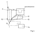
- the function of the agglomerate separator is to remove the backflowing agglomerates and conglomerates from the vortex chamber 2. These solids can then be reintroduced into the fluidized bed with the aid of regulated or uncontrolled distributors.
- Fig. 4 is one such Agglomeratabscheider with an annular gap opening 11 is shown.
- the solids of a float tank 12 are supplied from which they then the fluidized bed reactor again, z. B. evenly distributed on the circumference via a line 13, regulated (control 14) can be supplied.
- the invention By the invention of previously operated effort is reduced. Furthermore, the invention produces more stable operating conditions in wide load ranges, which are normally only possible in a narrower load range (gas flow rates). The influence of the upstream or downstream plants by the use of an agglomerate separator are minimized.
- the discharge of the solids laden gas occurs centrally upwards or laterally in one direction.
- roll flows are formed here which lead to a wall-like backflow within the reactor.
- this roll flow is uniform, but it can lead to an accumulation of solid, which then decreases as an agglomerate wall.
- the enrichment is partly avoided and the roll formation is not so pronounced, but the gas flow is inhomogeneous and it comes locally reinforced agglomeration.
- the constant-ring outlet is protected in conjunction with a gas-conducting cone, which further improves the discharge of the gas / solid mixture.
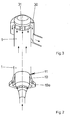
- the invention provides that through annularly arranged outlet openings 30 (see Fig. 3 ), which are preferably distributed uniformly around the circumference of the reactor 1, the product-laden gas is discharged in the radial direction and then optionally downwards. Solids which reach the reactor head in the core flow are discharged evenly in all directions (radially) by the shortest route and, above all, in all directions. As a result, the formation of agglomerates and the size of the forming agglomerates is reduced. For fluidized bed processes, which are operated in particular with different loads (gas flow rates), the invention leads to more stable operating conditions and the influence on the connected systems is considerably reduced.
- the constant-ring outlet may be provided with a Gasleitkegel 31, which further improves the discharge of the gas / solid mixture.
- the vortex chamber of the reactor 1 consists of a conical or parabolic housing 3, in which a likewise conical or parabolic installation 4 is located.
- Such a reactor can therefore also be referred to as a constant annular gap reactor.
- the gas velocity can be increased or reduced. If the amount of gas supplied to the reactor changes, an approximately constant flow velocity in the annular gap 2 can thus be achieved by lowering or raising the installation.
- the annular gap 2 can both be realized in such a way that the cross sections of the vortex chamber increase in size as well as diminish from bottom to top (see FIG Fig. 1a or 1b)
- the previously known complex countermeasures are superfluous. Furthermore, stable operating conditions are produced by the invention in wide load ranges, as they are usually possible only at constant gas flow rates. The influence of the upstream or downstream systems by the use of a constant-annular gap reactor is minimized.
- An annular gap fluidized-bed reactor which makes it possible by its inventive geometry and internals to make the operation of fluidized bed processes in particular with variable amounts of gas that are passed through the fluidized bed reactor, optimally, causing significant negative effects on upstream or downstream equipment parts are avoided , In addition, methods are protected which use the constant fluidized bed reactor according to the invention.
- the vortex chamber of a reactor 1 consists of a conical or parabolic housing 3, in which a likewise conical or parabolic installation 4 is located.
- Such a reactor can therefore also be referred to as a constant annular gap reactor.
- the annular gap geometry is changed and thus increases or reduces the gas velocity in the vortex chamber. If the amount of gas supplied to the reactor changes, an approximately constant flow velocity in the annular gap 2 can thus be achieved by lowering or raising the installation 4.
- the annular gap 2 can both be realized in such a way that the cross sections of the vortex chamber increase in size as well as diminish from bottom to top (see FIG Fig. 1a or 1b).
- the reactor has an agglomerate separator 10 which is designed as an annular gap opening 11 or through a multiplicity of offset openings on the circumference of the vortex chamber of a fluidized-bed reactor or as a discharge located in the center of the reactor.
- the openings of the Agglomeratabscheiders 10 may be located in the conical extension of the vortex chamber, directly at the transition between the conical extension and a cylindrical part, in the cylindrical part of a conventional fluidized bed reactor, at any point of the nozzle plate and at any position of the outer wall or the inner cone of an annular gap reactor ,
- the Agglomeratabscheider ensures that agglomerates do not fall within the vortex chamber down to the nozzle bottom, but rather before lateral z. B. are derived in a ring trough 10a. Remains of the agglomerate, which reach a gas inlet forming the nozzle bottom, are withdrawn by means of a discharge not shown in the nozzle bottom.
- the function of the agglomerate separator is to remove the backflowing agglomerates and conglomerates from the vortex chamber 2. These solids can then be reintroduced into the fluidized bed with the aid of regulated or uncontrolled distributors.
- Such an agglomerate separator is shown with an annular gap opening.
- the solids of a float tank 12 are supplied from which they then the fluidized bed reactor again, z. B. evenly distributed on the circumference via a line 13, regulated (control 14) can be supplied.
- a reactor is shown with annularly arranged outlet openings 30, which are preferably evenly distributed on the circumference of the reactor 1, through which the product-laden gas is discharged in the radial direction and then optionally downwards.
- Solids which reach the reactor head in the core flow are discharged evenly in all directions (radially) by the shortest route and, above all, in all directions.
- the invention leads to more stable operating conditions and the influence on the connected systems is considerably reduced.
- the constant-ring outlet may be provided with a Gasleitkegel 31, which further improves the discharge of the gas / solid mixture.
Landscapes
- Chemical & Material Sciences (AREA)
- Organic Chemistry (AREA)
- Chemical Kinetics & Catalysis (AREA)
- Engineering & Computer Science (AREA)
- Combustion & Propulsion (AREA)
- Devices And Processes Conducted In The Presence Of Fluids And Solid Particles (AREA)
- Fluidized-Bed Combustion And Resonant Combustion (AREA)
Priority Applications (1)
| Application Number | Priority Date | Filing Date | Title |
|---|---|---|---|
| EP10011011A EP2269721A1 (fr) | 2004-03-16 | 2005-03-15 | Réacteur à lit fluidisé avec une fente annulaire |
Applications Claiming Priority (2)
| Application Number | Priority Date | Filing Date | Title |
|---|---|---|---|
| DE102004013019A DE102004013019A1 (de) | 2004-03-16 | 2004-03-16 | Wirbelschichtreaktor |
| EP05005534A EP1577002B1 (fr) | 2004-03-16 | 2005-03-15 | Réacteur à lit fluidisé avec une fente annulaire |
Related Parent Applications (1)
| Application Number | Title | Priority Date | Filing Date |
|---|---|---|---|
| EP05005534A Division EP1577002B1 (fr) | 2004-03-16 | 2005-03-15 | Réacteur à lit fluidisé avec une fente annulaire |
Publications (2)
| Publication Number | Publication Date |
|---|---|
| EP2130580A2 true EP2130580A2 (fr) | 2009-12-09 |
| EP2130580A3 EP2130580A3 (fr) | 2009-12-23 |
Family
ID=34833154
Family Applications (3)
| Application Number | Title | Priority Date | Filing Date |
|---|---|---|---|
| EP10011011A Withdrawn EP2269721A1 (fr) | 2004-03-16 | 2005-03-15 | Réacteur à lit fluidisé avec une fente annulaire |
| EP05005534A Expired - Lifetime EP1577002B1 (fr) | 2004-03-16 | 2005-03-15 | Réacteur à lit fluidisé avec une fente annulaire |
| EP09010587A Withdrawn EP2130580A3 (fr) | 2004-03-16 | 2005-03-15 | Réacteur à lit fluidisé avec une fente annulaire |
Family Applications Before (2)
| Application Number | Title | Priority Date | Filing Date |
|---|---|---|---|
| EP10011011A Withdrawn EP2269721A1 (fr) | 2004-03-16 | 2005-03-15 | Réacteur à lit fluidisé avec une fente annulaire |
| EP05005534A Expired - Lifetime EP1577002B1 (fr) | 2004-03-16 | 2005-03-15 | Réacteur à lit fluidisé avec une fente annulaire |
Country Status (4)
| Country | Link |
|---|---|
| US (1) | US7399450B2 (fr) |
| EP (3) | EP2269721A1 (fr) |
| AT (1) | ATE448016T1 (fr) |
| DE (2) | DE102004013019A1 (fr) |
Families Citing this family (4)
| Publication number | Priority date | Publication date | Assignee | Title |
|---|---|---|---|---|
| US7446156B2 (en) * | 2006-05-16 | 2008-11-04 | Westlake Longview Corporation | Swirling fluidized-bed reactors for olefin polymerization |
| GB2497539B (en) * | 2011-12-13 | 2014-05-14 | Rolls Royce Plc | Apparatus for and method of treatment of a component in a fluidised bed with variable positioning of the treatment chamber |
| WO2014200605A2 (fr) * | 2013-03-15 | 2014-12-18 | Transtar Group, Ltd | Réacteur à noyau et système correspondant |
| CN111151211B (zh) * | 2020-01-20 | 2024-06-07 | 南通海晴医药科技有限公司 | 一种反应器及其使用方法 |
Family Cites Families (23)
| Publication number | Priority date | Publication date | Assignee | Title |
|---|---|---|---|---|
| FR1504435A (fr) * | 1965-11-24 | 1967-12-08 | Siderurgie Fse Inst Rech | Perfectionnements aux procédés de traitement en fluidisation et dispositif de mise en oeuvre |
| BE771545A (nl) * | 1971-08-19 | 1971-12-31 | Studiecentrum Kernenergi | Fluidizatiekolom, (uitv. f. decamps, g. dumont et w. goossens) |
| NL7306293A (fr) * | 1973-05-04 | 1974-11-06 | ||
| US4511434A (en) * | 1981-08-17 | 1985-04-16 | Standard Oil Company (Indiana) | Fluid bed retorting system |
| US4387667A (en) * | 1981-12-14 | 1983-06-14 | Combustion Engineering, Inc. | Fluidized bed distributor plate assembly |
| IT1150650B (it) * | 1982-03-10 | 1986-12-17 | Montedison Spa | Reattore a letto fluido |
| US4555328A (en) * | 1984-01-19 | 1985-11-26 | Mobil Oil Corporation | Method and apparatus for injecting liquid hydrocarbon feed and steam into a catalytic cracking zone |
| AT388806B (de) * | 1987-06-16 | 1989-09-11 | Waagner Biro Ag | Verfahren zur trocknung von schuettgutgemischen im wirbelbett und wirbelbetttrockner zur durchfuehrung des verfahrens |
| US4966101A (en) * | 1988-05-17 | 1990-10-30 | Ube Industries, Ltd. | Fluidized bed apparatus |
| GB9011407D0 (en) * | 1990-05-22 | 1990-07-11 | Shell Int Research | Apparatus and process for producing catalyst particles into a moving bed of catalyst |
| DD296224A5 (de) * | 1990-06-28 | 1991-11-28 | Zementanlagen- Und Maschinenbau Gmbh Dessau,De | Anstroemboden fuer wirbelschichtapparate |
| FR2674766A1 (fr) * | 1991-04-08 | 1992-10-09 | Inst Francais Du Petrole | Procede et dispositif de traitement des effluents gazeux issus d'une unite de craquage catalytique. |
| US5591411A (en) * | 1993-06-21 | 1997-01-07 | Exxon Research And Engineering Company | Catayltic cracking apparatus |
| US5562818A (en) * | 1993-07-16 | 1996-10-08 | Uop | FCC feed injection with non-quiescent mixing |
| BR9303773A (pt) * | 1993-09-13 | 1995-10-10 | Petroleo Brasileiro Sa | Sistema para separar suspensões de partículas de catalisador e mistura reagida de hidrocarbonetos e processo de craqueamento catalítico |
| FR2758277B1 (fr) * | 1997-01-13 | 1999-10-08 | Inst Francais Du Petrole | Separateur a enroulement direct de particules d'un melange gazeux et son utilisation en craquage thermique ou catalytique en lit fluidise |
| KR100584099B1 (ko) * | 1997-09-01 | 2006-05-30 | 앵스띠뛰 프랑세 뒤 뻬뜨롤 | 분리 및 스트리핑 장치와 이 장치를 사용한 유동층에서의 접촉 분해 |
| AU739185B2 (en) * | 1997-09-30 | 2001-10-04 | Mortimer Technology Holdings Ltd. | A process and apparatus for treating particulate matter |
| US7077949B2 (en) * | 2000-07-14 | 2006-07-18 | Shell Oil Company | FCC reactor vessel |
| DE10104184B4 (de) | 2001-01-25 | 2005-03-24 | Hüttlin, Herbert, Dr.h.c. | Verfahren zum Behandeln eines partikelförmigen Guts mit einem Überzugsmedium sowie Vorrichtung zur Durchführung eines derartigen Verfahrens |
| DE10104154C1 (de) | 2001-01-30 | 2002-07-25 | Engelbert Vodermair | Holzschneidevorrichtung |
| DE10146778B4 (de) * | 2001-09-22 | 2009-02-05 | Glatt Ingenieurtechnik Gmbh | Verfahren und Wirbelschichtanlage zur Herstellung von kompakten Feststoffpartikeln |
| US7244400B2 (en) * | 2003-11-25 | 2007-07-17 | Foster Wheeler Energy Corporation | Fluidized bed reactor system having an exhaust gas plenum |
-
2004
- 2004-03-16 DE DE102004013019A patent/DE102004013019A1/de not_active Withdrawn
-
2005
- 2005-03-15 AT AT05005534T patent/ATE448016T1/de not_active IP Right Cessation
- 2005-03-15 DE DE502005008463T patent/DE502005008463D1/de not_active Expired - Lifetime
- 2005-03-15 EP EP10011011A patent/EP2269721A1/fr not_active Withdrawn
- 2005-03-15 EP EP05005534A patent/EP1577002B1/fr not_active Expired - Lifetime
- 2005-03-15 EP EP09010587A patent/EP2130580A3/fr not_active Withdrawn
- 2005-03-16 US US11/080,547 patent/US7399450B2/en not_active Expired - Fee Related
Also Published As
| Publication number | Publication date |
|---|---|
| EP2269721A1 (fr) | 2011-01-05 |
| US7399450B2 (en) | 2008-07-15 |
| EP1577002B1 (fr) | 2009-11-11 |
| DE102004013019A1 (de) | 2005-10-06 |
| DE502005008463D1 (de) | 2009-12-24 |
| US20060002829A1 (en) | 2006-01-05 |
| EP2130580A3 (fr) | 2009-12-23 |
| EP1577002A1 (fr) | 2005-09-21 |
| ATE448016T1 (de) | 2009-11-15 |
Similar Documents
| Publication | Publication Date | Title |
|---|---|---|
| EP2512684B1 (fr) | Ensemble de séparation composé d'un séparateur par gravité suivi d'un séparatuer centrifuge | |
| DE69203664T2 (de) | Abscheidung von in einem Gasstrom suspendierten Feststoffen. | |
| EP2178630B1 (fr) | Système de réacteurs à lit fluidisé | |
| EP1663434B1 (fr) | Reacteur a faisceau tubulaire a distributeur de fluides multiphase | |
| EP1658891B1 (fr) | Procédé pour régler le taux des particules circulant dans un appareil comprenant un cyclone et un réacteur | |
| EP0270531B1 (fr) | Reacteur a lit mobile | |
| EP3077097B1 (fr) | Buse de distribution de gaz et réacteur | |
| EP2201992A1 (fr) | Procédé et dispositif destinés à épaissir de la boue charriée par les eaux usées | |
| DE69925303T2 (de) | Trennungsgerät | |
| DE69319916T2 (de) | Methode und vorrichtung zum austrag von partikelförmigem guss aus einem druckbehälter | |
| DE60314502T2 (de) | Verfahren und vorrichtung zum erleichtern einer gleichmässigeren dampfverteilung in stoff- und wärmeaustauschkolonnen | |
| DE3028293A1 (de) | Entgasungseinrichtung fuer einen fliessbett-abfluss | |
| EP1577002B1 (fr) | Réacteur à lit fluidisé avec une fente annulaire | |
| DE102011052788A1 (de) | Verfahren und Vorrichtung zur Reinigung von Abgasen | |
| CH430397A (de) | Gravimetrische Ausgleichseinrichtung für Schüttgüter | |
| EP4288176B1 (fr) | Séparateur de boues | |
| EP4228821B1 (fr) | Buse de pulvérisation de substances et procédés de contrôle ou de régulation de la buse | |
| DE19521741C2 (de) | Durchlaufabscheider mit zwei Stufen zum Abtrennen von Feststoffteilchen aus einer strömenden Flüssigkeit | |
| DE19700029B4 (de) | Wirbelschichtapparat | |
| EP0665768A1 (fr) | Procede et dispositif d'humidification des cendres volantes des filtres de centrales electriques | |
| DE3017825A1 (de) | Verfahren und vorrichtung zur abfuehrung von festkoerperpartikeln aus einem druckbehaelter | |
| AT505752B1 (de) | Vorrichtung zum verandern des venturikehlenquerschnitts eines venturisystems | |
| DE102004046248B4 (de) | Vorrichtung zur variablen Gaszufuhr für Strahlschichtapparaturen | |
| EP1583605B1 (fr) | Filtre et procédé de lavage à contre-courant du filtre | |
| DE68905473T2 (de) | Verteilerplatte in einem wirbelbettreaktor, wirbelbettreaktor und verfahren zum inbetriebsetzen eines wirbelbettreaktors. |
Legal Events
| Date | Code | Title | Description |
|---|---|---|---|
| PUAI | Public reference made under article 153(3) epc to a published international application that has entered the european phase |
Free format text: ORIGINAL CODE: 0009012 |
|
| PUAL | Search report despatched |
Free format text: ORIGINAL CODE: 0009013 |
|
| AC | Divisional application: reference to earlier application |
Ref document number: 1577002 Country of ref document: EP Kind code of ref document: P |
|
| AK | Designated contracting states |
Kind code of ref document: A2 Designated state(s): AT BE BG CH CY CZ DE DK EE ES FI FR GB GR HU IE IS IT LI LT LU MC NL PL PT RO SE SI SK TR |
|
| AK | Designated contracting states |
Kind code of ref document: A3 Designated state(s): AT BE BG CH CY CZ DE DK EE ES FI FR GB GR HU IE IS IT LI LT LU MC NL PL PT RO SE SI SK TR |
|
| 17P | Request for examination filed |
Effective date: 20100622 |
|
| 17Q | First examination report despatched |
Effective date: 20100720 |
|
| STAA | Information on the status of an ep patent application or granted ep patent |
Free format text: STATUS: THE APPLICATION IS DEEMED TO BE WITHDRAWN |
|
| 18D | Application deemed to be withdrawn |
Effective date: 20121002 |