EP4288176B1 - Séparateur de boues - Google Patents
Séparateur de boues Download PDFInfo
- Publication number
- EP4288176B1 EP4288176B1 EP22711184.6A EP22711184A EP4288176B1 EP 4288176 B1 EP4288176 B1 EP 4288176B1 EP 22711184 A EP22711184 A EP 22711184A EP 4288176 B1 EP4288176 B1 EP 4288176B1
- Authority
- EP
- European Patent Office
- Prior art keywords
- inlet
- outlet
- opening
- sludge separator
- end section
- Prior art date
- Legal status (The legal status is an assumption and is not a legal conclusion. Google has not performed a legal analysis and makes no representation as to the accuracy of the status listed.)
- Active
Links
Images



Classifications
-
- B—PERFORMING OPERATIONS; TRANSPORTING
- B01—PHYSICAL OR CHEMICAL PROCESSES OR APPARATUS IN GENERAL
- B01D—SEPARATION
- B01D21/00—Separation of suspended solid particles from liquids by sedimentation
- B01D21/24—Feed or discharge mechanisms for settling tanks
- B01D21/2405—Feed mechanisms for settling tanks
- B01D21/2411—Feed mechanisms for settling tanks having a tangential inlet
-
- B—PERFORMING OPERATIONS; TRANSPORTING
- B01—PHYSICAL OR CHEMICAL PROCESSES OR APPARATUS IN GENERAL
- B01D—SEPARATION
- B01D21/00—Separation of suspended solid particles from liquids by sedimentation
- B01D21/0024—Inlets or outlets provided with regulating devices, e.g. valves, flaps
-
- B—PERFORMING OPERATIONS; TRANSPORTING
- B01—PHYSICAL OR CHEMICAL PROCESSES OR APPARATUS IN GENERAL
- B01D—SEPARATION
- B01D21/00—Separation of suspended solid particles from liquids by sedimentation
- B01D21/24—Feed or discharge mechanisms for settling tanks
- B01D21/2427—The feed or discharge opening located at a distant position from the side walls
-
- B—PERFORMING OPERATIONS; TRANSPORTING
- B01—PHYSICAL OR CHEMICAL PROCESSES OR APPARATUS IN GENERAL
- B01D—SEPARATION
- B01D21/00—Separation of suspended solid particles from liquids by sedimentation
- B01D21/24—Feed or discharge mechanisms for settling tanks
- B01D21/2444—Discharge mechanisms for the classified liquid
Definitions
- the present invention relates to a sludge separator, in particular for a vehicle washing system, with a sedimentation basin that has a side wall and a base.
- the sedimentation basin is divided vertically into a lower sediment region, an intermediate region and an upper liquid exchange region.
- the sludge separator also has an inlet for supplying a liquid carrying solid particles into the sedimentation basin, which inlet has an end section with an inlet opening, wherein the inlet opening is arranged vertically in the upper liquid exchange region and opens into the sedimentation basin in a horizontal plane in an edge region of the sedimentation basin.
- the sludge separator also has an outlet for discharging liquid from the sedimentation basin, which outlet has an outlet opening that is arranged vertically in the upper liquid exchange region.
- a sludge separator for separating particles contained in a liquid is known.
- the sludge separator has an upper inlet opening, a separator housing and a lower outlet opening.
- the inlet opening and the outlet opening are arranged coaxially to the vertical housing axis.
- the flow through the sludge separator is in a vertical direction from the upper inlet opening to the lower outlet opening.
- the supplied liquid passes through a particle separator with flow deflection elements, which cause a flow deflection between axial and radial directions.
- the substances to be separated are separated by these flow deflection elements. They sediment in a collecting pot and are led out from there via a drain line.
- sludge separators which work according to the cyclone principle.
- the WO 2009/122127 A1 a sludge separator with a pot-shaped separating tank with an inlet arranged in the upper tank area for supplying liquid into the separating tank and an outlet arranged in the upper tank area for discharging the liquid from the separating tank.
- a pipe open at the bottom is arranged coaxially inside the separating tank.
- the outlet is connected in a communicating manner to the interior of the pipe, the inlet opens into an annular space between the tank wall and the pipe.
- the inlet and the outlet are arranged in such a way that liquid introduced into the separating tank is discharged in a cyclone-like movement along the tank wall downwards and then flows upwards through the pipe to the outlet within the cyclone-like downward-flowing liquid. Solid particles separated by the cyclone effect sink down along the tank wall into a sludge settling chamber provided at the lower end of the tank.
- a sludge trap for wastewater that is contaminated with sediment.
- the sludge trap consists of a calming basin that has a lower side inlet and an upper outlet.
- the mouth of the inlet is aligned approximately tangentially to the wall of the calming basin.
- the upper outlet is located approximately in the center of the calming basin.
- the central upper outlet is surrounded at a distance by a hollow body-shaped, permeable insert that is placed vertically around it.
- the geometry of the inlet and outlet creates a spiral flow around the hollow body-shaped insert, which flows in a spiral from bottom to top to the outlet.
- a separation plant with a similar sludge trap is in the DE 94 12 973 U1 described.
- the sludge trap of this separation system is intended to separate, for example, suspended solids in the wastewater of a car wash.
- the DE 92 08 367 U1 A separating tank which can be used either as a sludge trap or as a pre-separator with an inlet and an outlet.
- the inlet and outlet of this separating tank are arranged at approximately the same height in the upper area opposite each other on the edge of the tank.
- impact plates are mounted on the inlet and outlet.
- the dirty water from the washing system should be treated in such a way that solid particles carried along by the protective water settle in the sedimentation basin.
- the separation performance of the sludge separator should be as high as possible.
- the US 2007/0267342 A1 describes a separation system for retaining floating and non-floating particles in a storage chamber of a treatment tank.
- the storage chamber includes an inlet and an outlet.
- the outlet is positioned in the storage chamber to minimally disturb the primary and secondary liquid flow patterns in the storage chamber.
- a circular or rotating flow pattern is created in the storage chamber and an outlet opening of the storage chamber is centered on an axis of the circular flow pattern.
- the EP 0703324 A1 describes a sludge trap for wastewater contaminated with sediment, consisting of a settling tank with an upper lateral inlet and an upper outlet. The mouth of the inlet is aligned at least approximately tangentially to the wall of the settling tank and the upper outlet is located approximately in the center of the settling tank.
- the present invention is therefore based on the object of specifying a sludge separator which has an improved separation performance for solid particles which are fed to the sedimentation tank via the introduced liquid.
- the end section of the sludge separator described above is aligned so that the supplied liquid flows tangentially into the sedimentation basin and the outlet opening is arranged in a horizontal plane in a central region of the sedimentation basin.
- Sludge is understood to mean solid particles carried, e.g. suspended, in a liquid stream.
- a sludge separator in the sense of the invention is therefore understood to be a device for separating solid particles from a liquid stream.
- the edge region of the sedimentation basin is understood to be a radially outer region of the sedimentation basin in a horizontal plane in which the inlet opening is arranged.
- the largest horizontal extension of the sedimentation basin results in at least one horizontal direction.
- this largest horizontal extension is the radius of the circular disk.
- the edge region ranges from the outside 0% to 30%, in particular from 0% to 10%, of the largest horizontal extension in the direction of the geometric center.
- the middle area of the sedimentation basin is understood to mean a central area of the sedimentation basin in a horizontal plane in which the drain opening is arranged. Starting from the geometric center of this horizontal cross section of the sedimentation basin, the middle area extends from the geometric center to 40%, in particular 30%, to the edge of the sedimentation basin in the respective horizontal direction.
- the end section of the inlet is understood to mean the section of the inlet which essentially determines the flow direction of the liquid emerging from the inlet opening.
- the end section is in particular straight. It is essentially tangential in relation to the sedimentation basin and in particular essentially horizontally aligned. A tangential alignment is understood to mean that the flow direction at the inlet opening is essentially parallel to a tangent at the edge of the sedimentation basin.
- the invention is based on the finding that an improved separation performance of the sludge separator can be achieved by the liquid containing solid particles, which is fed to the sedimentation tank, forming a has a decreasing flow velocity so that solid particles can settle.
- Vertical flows should be avoided. Simulations have shown that, depending on the inlet geometry, a liquid roller can form which transports already sedimented material back into the upper liquid layers. On the other hand, it has been found that flows can form through which the liquid carrying solid particles is led directly from the inlet to the outlet. This is disadvantageous because no solid particles can be separated.
- a substantially tangential and/or substantially horizontal orientation of the end section is thus understood to mean that the end section is aligned in such a way that a peripheral, circulating flow is formed.
- the geometry and arrangement of the inlet and outlet according to the invention thus advantageously ensures that the residence time of the newly supplied liquid in the sedimentation basin is sufficiently long so that solid particles can be separated.
- a flow that leads directly from the inlet opening to the outlet opening is prevented.
- vertical flows are prevented, which are detrimental to the separation performance of the sludge separator.
- the sludge separator according to the invention can provide improved separation performance.
- the inner wall of the side wall of the sedimentation tank is particularly cylindrical in shape. In a horizontal cross-section, the inner wall thus forms a circle.
- the tangential inflow of the liquid at the outer edge of the sedimentation tank creates a slow horizontal flow in the upper liquid exchange area, which causes a very small flow in the vertical direction, so that no particles that have already sedimented are transported upwards.
- the liquid volume remains in the sedimentation tank for a long time, so that solid particles can be separated particularly well.
- the inner wall of the sedimentation basin can also have a different geometry.
- it can be semicircular or rectangular.
- the liquid introduced via the inlet has essentially no rotation of its own due to the lamellae in the end section of the inlet.
- the flow circles the sedimentation basin essentially in the horizontal plane of the inlet opening and is slowed down in the process.
- the downward component of the flow is very small throughout the sedimentation basin. Simulations have shown that the downward component of the flow is about an order of magnitude lower than the flow velocity along the main component, i.e. in particular in the tangential direction.
- the flow formed by the lamellae in the end section of the inlet is advantageous in conjunction with an outlet opening located in the middle area of the sedimentation basin.
- a substantially flow-free zone is formed because the self-rotation of the supplied liquid is prevented by the lamellae.
- the geometry of the inlet and outlet according to the invention thus ensures that the residence time of the liquid in the sedimentation basin is sufficiently long so that solid particles can be separated. In this way, the sludge separator according to the invention can provide improved separation performance.
- the lamellae are arranged in particular parallel to one another and in the flow direction of the supplied liquid in the end section.
- the lamellae extend in particular in the axial direction of the end section of the inlet.
- the lamellae have flat flow guide surfaces, the normals of which are each aligned orthogonally to the axial direction of the end section.
- the flow guide surfaces enable the lamellae to generate a self-rotation-free flow in the direction of the inlet opening, where the liquid is then guided into the sedimentation basin.
- the lamellae can divide the end section into several separate flow channels, particularly in a cross-section.
- the lamellae can form flow channels next to each other.
- the lamellae are aligned vertically. It has been found that in this case a particularly uniform horizontal flow can be formed in the upper liquid exchange area of the sedimentation basin, which prevents particles that have already settled from being transported upwards by vertical flows. The normals of the flow guide surfaces of the lamellae are therefore aligned horizontally in this case.
- the extension of the lamellae in the axial direction of the end section is in particular greater than the extension in a cross-sectional direction of the end section.
- the lamellae are thus elongated in the axial direction of the end section. This can prevent the supplied liquid from rotating in a particularly effective way.
- one or more further inlet openings are provided in addition to the said inlet opening, the end section of this further inlet opening or the end sections of these further inlet openings are aligned in the same way as the end section of the one mentioned inlet opening, i.e. the supplied liquid also flows in via the further inlet opening or the further inlet openings tangentially to the side wall of the sedimentation basin.
- the sludge separator according to the invention has in particular only the one mentioned inlet opening. Thus, in particular, no further inlet opening is provided.
- the ratio of the entire cross-sectional area of the inlet to the smallest cross-sectional area of the outlet is in a range from 2 to 10, in particular in a range from 4 to 8 and preferably in a range from 5 to 7.
- the outlet geometry thus has a smaller cross-section than the inlet geometry. This leads to the liquid flow being dammed up in the basin. This is particularly advantageous when liquid is supplied intermittently, as in a gantry washing system, for example.
- the pulse-shaped inflow of the liquid is then stretched on the outlet side to a longer time interval for the outlet. This increases the average residence time of the liquid in the sedimentation basin, which in turn improves the separation performance of the sludge separator.
- the drain opening of the sludge separator according to the invention can be directed downwards or upwards.
- An upwards orientation of the drain opening is advantageous because the proportion of solid particles that still flows slightly upwards in this case reaches the drain opening less frequently.
- a downwards orientation However, a drain opening can be advantageous if the drain is to be more easily integrated into an existing sedimentation tank.
- the outlet has an overflow opening which is arranged above the outlet opening.
- an overflow opening is provided in order to be able to drain off an excessive amount of liquid introduced into the sedimentation basin.
- the overflow opening is particularly important when the outlet cross-section of the outlet is smaller than the inlet cross-section of the inlet.
- the drain has a vertically aligned first drain pipe section, on one side of which the drain opening is formed, and which on the other side merges into a horizontally aligned second drain pipe section, which in turn opens into a third drain pipe section, which has a larger cross-section.
- the third drain pipe section can have a weir with an overflow edge and the overflow opening above the mouth of the second drain pipe section. This advantageously allows the overflow opening to be compactly integrated into the pipe sections of the drain.
- overflowing liquid can be combined with the liquid that is drained via the drain opening.
- the upper liquid exchange area in the vertical direction takes up at most the upper 0% to 30%, in particular the upper 0% to 10%, of the height of the sedimentation basin. This prevents vertically oriented flows in the sedimentation basin, which can lead to particles of the sediment being transported upwards to the discharge opening. In this way, the separation performance of the sludge separator can be improved.
- the sediment area occupies, for example, at most the lower 0% to 50%, in particular the lower 0% to 30%, of the height of the sedimentation basin.
- the inlet opening is arranged above the outlet opening. Due to the vertical distance between the inlet opening and the outlet opening, the sludge separator can be adapted to an intermittent inflow of liquid. However, if the inlet opening is above the If the overflow edge is arranged, the liquid level can only rise to the overflow edge. The liquid is then drained through the overflow opening. In addition, since both the inlet opening and the outlet opening are arranged in the upper area of the sedimentation basin, horizontal flows are encouraged. In particular, the formation of vertical vortices is avoided.
- the inlet opening is arranged at approximately the same height as the outlet opening.
- the height of the inlet opening differs in particular by less than 15%, in particular less than 10%, of the total height of the sedimentation tank from the height of the outlet opening.
- the inlet opening is arranged vertically in the area of the liquid level of the sedimentation tank, which can, however, fluctuate due to different inflow and outflow rates.
- the inlet opening can also be arranged temporarily at least partially above the liquid level.
- the drain comprises a suction line which is connected to the drain opening in a gas-tight manner.
- the suction line opens into an outlet opening on the outlet side, which is arranged below the drain opening.
- the suction line and the height of the drain opening can be used to define the liquid level in the sedimentation basin when no liquid is supplied via the inlet.
- the siphon effect is used to empty the sludge separator to a defined volume so that it can then absorb a predetermined amount of liquid again.
- the design of the sludge separator with the suction line is particularly advantageous when an existing installation of a drain in a sludge separator is replaced by the geometry of the drain according to the invention.
- the height of the drain may not be able to be lowered in order to create the corresponding volume for the dirty water supplied.
- the suction line it is sufficient to lower the height of the drain opening to ensure that liquid is drained up to the height of the drain opening. This requires that the liquid level in any collecting basin provided outside the sedimentation basin, into which the outlet opening of the suction line flows, is lower than the height of the outlet opening.
- the suction line can also prevent a blockage in the inlet if not enough liquid can be drained via the outlet, since at least a defined volume of liquid can be supplied without it having to be drained away. On the other hand, such a blockage can be prevented by the overflow opening if it is arranged approximately at the height of the inlet opening.
- the following effects which are achieved by the geometry of the inlet and the outlet, are combined with one another:
- the path that the flow takes from the inlet opening to the outlet opening is extended. This results in an extended residence time of the liquid in the sedimentation tank.
- the flow is prevented from hitting the inner walls of the sedimentation tank.
- the inner walls of the sedimentation tank are only approached at a very acute angle.
- an opposite flow is reduced. This ensures that no fast currents form in a vertical direction, which in turn prevents sedimented particles from being transported upwards.
- a throttling in the outlet geometry causes the liquid to accumulate in the sedimentation tank. This extends the residence time of the liquid in the sedimentation tank, which improves the separation performance of the sludge separator.
- the invention further relates to a vehicle washing system with a sludge separator as described above.
- vehicle washing system is in particular a gantry washing system in which dirty water is intermittently fed to the sludge separator.
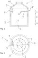
- the basic structure of the sludge separator 1 according to the invention is described below with reference to the Figures 1 to 3 explained.
- the sludge separator 1 is part of a water circuit of a gantry washing system.
- the liquid carrying solid particles fed to the sludge separator 1 is therefore also referred to below as dirty water.
- the sludge separator 1 comprises a cylindrical side wall 2, which is closed at the bottom by a circular disk-shaped base 3, so that a sedimentation basin 4 is formed inside the sludge separator 1.
- the sludge separator 1 is closed at the top of the cylindrical side wall 4 by a conical cover 18.
- the sedimentation basin 4 is divided into a lower sediment region A, an intermediate region B and an upper liquid exchange region C.
- the upper liquid exchange region C occupies, for example, the upper 0% to 30%, in particular the upper 0% to 10%, of the height of the sedimentation basin 4.
- the sediment region A occupies, for example, the lower 0% to 50%, in particular the lower 0% to 30%, of the height of the sedimentation basin 4.
- An inlet 5 and an outlet 7 are provided in the upper liquid exchange area C.
- a first opening 6 for the inlet 5 and a second opening 8 for the outlet 7 are arranged in the side wall 2.
- the inlet 5 has an inlet opening 9 through which dirty water containing solid particles can be fed to the sedimentation basin 4.
- the outlet 7 has an outlet opening 11 through which liquid can be led out of the sedimentation basin 4. Further details of the inlet 5 and the outlet 7 will be explained later.
- the inlet opening 9 is located approximately at the height of the outlet opening 11. In a state of equilibrium for the supplied waste water and the discharged liquid, the inlet opening 9 is thus arranged at the height of the liquid level in the sedimentation basin 4. However, both the inlet opening 9 and the outlet opening 11 are located in the upper part of the sludge separator 1, ie in the upper liquid exchange area C.
- an edge region D and a central region E are formed in a horizontal plane in which the inlet opening 9 and the outlet opening 11 are arranged.
- the edge region D extends from the outside 0% to 30%, in particular from 0% to 10%, of the radius R in the direction of the center point Z and the central region E extends from the center point Z to 40%, in particular 30%, of the radius R in the direction of the edge at the side wall 2 of the sedimentation basin 4.
- the radius R of the sedimentation basin 4 is 1 m.
- the inlet 5 has a first inlet pipe section 5-1.
- This first inlet pipe section 5-1 is inserted with an opening into the first opening 6 of the side wall 2. It is aligned horizontally.
- a second inlet pipe section 5-2 which is aligned vertically.
- This second inlet pipe section is followed by a third inlet pipe section 5-3 which is also referred to as the end section 5-3 of the inlet 5.
- This end section 5-3 is aligned such that the waste water supplied via the inlet 5 flows tangentially into the sedimentation basin 4. It is also aligned horizontally.
- the inlet pipe sections 5-1 to 5-3 have a diameter of 150 mm.
- the inlet opening 9 is located in the outer edge area D of the sedimentation basin 4. The normal of the area formed by the inlet opening 9 is tangential to the side wall 2 of the sedimentation basin 4 and aligned horizontally.
- the sludge separator 1 has only one inlet opening 9 for supplying dirty water into the sedimentation tank 4.
- slats 10 are arranged, which are aligned parallel to one another.
- the end section 5-3 is cylindrical, so that an axial direction of the end section 5-3 is defined. This axial direction is aligned horizontally and tangentially to the cylindrical side wall 2.
- the slats 10 are aligned vertically. They divide the end section 5-3 into a cross section perpendicular to the axial direction of the end section 5-3 into several separate flow channels.
- the slats 10 have flat flow guide surfaces, the normals of which are each aligned orthogonally to the axial direction of the end section 5-3. The normals of the flow guide surfaces of the slats 10 are thus aligned horizontally.
- the end section 5-3 opens into the inlet opening 9.
- the inlet opening 9 is divided into the openings which are formed by the flow channels formed by the slats 10.
- the total area of the inlet opening 9 has the radius Rz.
- the normal of the area of the inlet opening 9 is aligned horizontally and tangential with respect to the cylindrical side wall 2.
- the slats 10 are designed as thin, flat plates that are inserted vertically into the third inlet pipe section 5-3, with their extension in the axial direction of the third inlet pipe section 5-3 being greater than in the cross-sectional direction of the inlet pipe section 5-3.
- the slats 10 ensure that the supplied dirty water, which tends to rotate due to the angular arrangement of the three inlet pipe sections 5-1 to 5-3, is guided in the end section 5-3 in such a way that this rotation is lost and the dirty water enters the sedimentation basin 4 tangentially and horizontally at the inlet opening 9, whereby any vertical velocity component of the incoming dirty water is minimized.
- the drain 7 has a first drain pipe section 7-1, at one end of which the drain opening 11 is formed.
- the first drain pipe section 7-1 is aligned vertically.
- the normal of the surface formed by the drain opening 11 is aligned vertically. In the embodiment described here, the normal of the surface of the drain opening 11 points downwards. Alternatively, the normal of the surface of the drain opening 11 can also point upwards.
- the first drain pipe section 7-1 merges into a longer second drain pipe section, which is aligned horizontally.
- the second drain pipe section 7-2 merges in turn into a third drain pipe section 7-3, which has a larger cross-section. The downstream end of the third drain pipe section 7-3 is inserted into the second opening 8 of the side wall 2.
- the inner diameter of the third drain pipe section 7-3 is 140 mm, the inner diameter of the drain opening 11, the first drain pipe section 7-1 and the second drain pipe section 7-2 is 25 mm each, and the overflow edge 13 is arranged 72 mm above the lower junction of the second drain pipe section 7-2 into the third drain pipe section 7-3.
- the drain 7 is inserted into the sludge separator 1 in such a way that the drain opening 11 is located in the middle area E of the sedimentation tank 4. Liquid is thus drained from the middle of the sedimentation tank 4 via the drain 7.
- the outlet 7 has a smaller cross-section than the inlet 5, so that the dirty water 5 can be supplied via the inlet 5 at a higher volume rate than the liquid is discharged from the sedimentation tank 4 via the outlet 7.
- the ratio of the smallest cross-sectional area of the inlet 5 to the smallest cross-sectional area of the outlet 7 is six.
- an overflow opening 14 is provided in the outlet 7, which is arranged above the outlet opening 11.
- the overflow opening 14 is limited at the bottom by a weir 12, which forms an overflow edge 13.
- the weir 12 is located at the junction of the second outlet pipe section 7-2 and the third outlet pipe section 7-3, as shown in the Figures 6 and 7 shown.
- the upper fluid exchange area C (see Figure 2 ) can be defined so that it extends upwards to overflow edge 13.
- a suction line 15 is provided.
- This suction line 15 is connected in a gas-tight manner to the drain opening 11.
- the suction line 15 can, for example, be connected to the opening of the second drain pipe section 7-2 at the junction of the second drain pipe section 7-2 and the third drain pipe section 7-3 (see Figure 7 ).
- the suction line 15 is then led downwards outside the side wall 2, for example into a collecting basin.
- the suction line 15 has an outlet opening 16 outside the side wall 2, which is arranged below the drain opening 11.
- the liquid level in the sedimentation basin 4 can be set by the height of the drain opening 11 independently of the highest point of the drain 7 due to the siphon effect when no more dirty water is fed in via the inlet 5.
- This liquid level is then at the level of the drain opening 11, provided that the liquid level in a collecting basin into which the outlet opening 16 opens is below the height of the drain opening 11.
- dirty water for example from a gantry washing system
- the liquid level rises.
- the flow behavior in the sedimentation basin 4 which was observed during the simulation, can be summarized as follows:
- the inflow of liquid causes the liquid level to rise.
- a rotational flow is created.
- At the beginning of the inflow process in addition to the tangential flow direction in the sedimentation basin 4, there is a slight vertical flow direction downwards, which, however, decreases again as soon as the rotational flow has stabilized. If a volume of liquid has circumferentially circled the sedimentation basin 4, a slight downward flow occurs when this volume of liquid meets the inflowing liquid again.
Landscapes
- Chemical & Material Sciences (AREA)
- Chemical Kinetics & Catalysis (AREA)
- Sewage (AREA)
- Cyclones (AREA)
- Sink And Installation For Waste Water (AREA)
Claims (15)
- Décanteur de boues (1), comprenant :une cuve de décantation (4), présentant une paroi latérale (2) et un fond (3), ladite cuve de décantation (4) étant verticalement divisée en une zone de décantation en partie basse (A), une zone intermédiaire (B) et une zone d'échange de liquides en partie haute (C),une arrivée (5) destinée à amener un liquide transportant des particules solides dans la cuve de décantation (4), ladite arrivée présentant une partie terminale (5-3) munie d'un orifice d'alimentation (9),l'orifice d'alimentation (9) étant disposé verticalement dans la zone d'échange de liquides en partie haute (C) et débouchant dans un plan horizontal dans une zone périphérique de la cuve de décantation (4) à l'intérieur de la cuve de décantation (4), la partie terminale (5-3) étant orientée de sorte que le liquide transporté pénètre tangentiellement dans la cuve de décantation (4),et, pour permettre au liquide d'être évacué de la cuve de décantation (4), une évacuation (7) présentant un orifice d'évacuation (11) disposé verticalement dans la zone d'échange de liquides en partie haute (C), l'orifice d'évacuation (11) étant disposé dans un plan horizontal dans une zone médiane de la cuve de décantation (4),
caractérisé en ce queplusieurs lamelles (10) sont disposées dans la partie terminale (5-3) de l'arrivée (5). - Décanteur de boues (1) selon la revendication 1,
caractérisé en ce que
la partie terminale (5-3) de l'arrivée (5) est de forme rectiligne. - Décanteur de boues (1) selon l'une quelconque des revendications 1 ou 2,
caractérisé en ce que
la partie terminale (5-3) de l'arrivée (5) est orientée à peu près tangentiellement à la cuve de décantation (4). - Décanteur de boues (1) selon l'une quelconque des revendications précédentes, caractérisé en ce que
la partie terminale (5-3) de l'arrivée (5) est orientée à peu près horizontalement. - Décanteur de boues (1) selon l'une quelconque des revendications précédentes, caractérisé en ce que
les lamelles (10) sont parallèles les unes aux autres. - Décanteur de boues (1) selon l'une quelconque des revendications précédentes, caractérisé en ce que
les lamelles (10) sont chacune disposées dans la direction d'écoulement du liquide à amener dans la partie terminale (5-3). - Décanteur de boues (1) selon l'une quelconque des revendications précédentes, caractérisé en ce que
les lamelles (10) présentent des surfaces de guidage d'écoulement planes dont la normale est orientée orthogonalement par rapport à la direction axiale de la partie terminale (5-3). - Décanteur de boues (1) selon l'une quelconque des revendications précédentes, caractérisé en ce que
les lamelles (10) divisent une section transversale de la partie terminale (5-3) en plusieurs canaux d'écoulement distincts. - Décanteur de boues (1) selon l'une quelconque des revendications précédentes, caractérisé en ce que
les lamelles (10) sont orientées verticalement. - Décanteur de boues (1) selon l'une quelconque des revendications précédentes, caractérisé en ce que
l'étendue des lamelles (10) dans la direction axiale de la partie terminale (5-3) est plus grande que dans la direction de la section transversale de la partie terminale (5-3). - Décanteur de boues (1) selon l'une quelconque des revendications précédentes, caractérisé en ce que
le rapport entre la plus petite aire de la section transversale de l'arrivée (5) et la plus petite aire de la section transversale de l'évacuation (7) se situe dans une plage de 2 à 10 et en particulier dans une plage de 4 à 8. - Décanteur de boues (1) selon l'une quelconque des revendications précédentes, caractérisé en ce que
l'évacuation (7) présente un orifice de trop-plein (14) disposé au-dessus de l'orifice d'évacuation (11). - Décanteur de boues (1) selon la revendication 12,
caractérisé en ce quel'évacuation (7) présente un premier tronçon de tube d'évacuation (7-1) orienté verticalement qui, d'un côté, constitue l'orifice d'évacuation (11) et, de l'autre, se poursuit sous la forme d'un deuxième tronçon de tube d'évacuation (7-2) orienté horizontalement, lequel débouche à son tour dans un troisième tronçon de tube d'évacuation (7-3) de section transversale plus grandeet en ce que le troisième tronçon de tube d'évacuation (7-3) présente, au-dessus de la jonction avec le deuxième tronçon de tube d'évacuation (7-2), présente un déversoir (12) muni d'un bord-déversoir (13) et d'un orifice de trop-plein (14). - Décanteur de boues (1) selon l'une quelconque des revendications précédentes, caractérisé en ce quel'évacuation (7) comprend une conduite d'aspiration (15) qui est reliée à l'orifice d'évacuation (11) de manière étanche au gazet en ce que, du côté évacuation, la conduite d'aspiration (15) débouche dans un orifice d'évacuation (16) qui est disposé en dessous de l'orifice d'évacuation (11) et au-dessus d'un fond de la cuve de décantation (2).
- Installation de lavage des véhicules comportant un décanteur de boues (1) selon l'une quelconque des revendications précédentes.
Applications Claiming Priority (2)
| Application Number | Priority Date | Filing Date | Title |
|---|---|---|---|
| DE102021105798.1A DE102021105798A1 (de) | 2021-03-10 | 2021-03-10 | Schlammabscheider |
| PCT/EP2022/054849 WO2022189173A2 (fr) | 2021-03-10 | 2022-02-25 | Séparateur de boues |
Publications (2)
| Publication Number | Publication Date |
|---|---|
| EP4288176A2 EP4288176A2 (fr) | 2023-12-13 |
| EP4288176B1 true EP4288176B1 (fr) | 2024-12-25 |
Family
ID=80786818
Family Applications (1)
| Application Number | Title | Priority Date | Filing Date |
|---|---|---|---|
| EP22711184.6A Active EP4288176B1 (fr) | 2021-03-10 | 2022-02-25 | Séparateur de boues |
Country Status (7)
| Country | Link |
|---|---|
| US (1) | US20240216836A1 (fr) |
| EP (1) | EP4288176B1 (fr) |
| CN (1) | CN117177802A (fr) |
| DE (1) | DE102021105798A1 (fr) |
| ES (1) | ES3020532T3 (fr) |
| FI (1) | FI4288176T3 (fr) |
| WO (1) | WO2022189173A2 (fr) |
Families Citing this family (1)
| Publication number | Priority date | Publication date | Assignee | Title |
|---|---|---|---|---|
| CN119258607B (zh) * | 2024-10-31 | 2025-10-21 | 四川兴蔚蓝科技有限公司 | 一种矿浆浓密槽 |
Family Cites Families (19)
| Publication number | Priority date | Publication date | Assignee | Title |
|---|---|---|---|---|
| FR2536672B1 (fr) * | 1982-11-26 | 1994-07-08 | Chaudrofrance Sa | Decanteur lamellaire centrifuge |
| US5180407A (en) * | 1991-11-14 | 1993-01-19 | Demarco Thomas M | Vacuum loader with vaned and short tangential separator |
| DE9208367U1 (de) | 1992-06-23 | 1992-09-03 | Buderus Guss GmbH, 6330 Wetzlar | Abscheidebehälter |
| DE4400712A1 (de) * | 1994-01-13 | 1995-07-20 | Passavant Werke | Verfahren und Einrichtung zum Abtrennen von fetthaltigen Speiseresten aus diese enthaltenden Spülwässern |
| DE9412973U1 (de) | 1994-08-11 | 1994-10-20 | Passavant-Werke Ag, 65326 Aarbergen | Abscheideanlage für mit Leichtstoffen verschmutzte Abwässer |
| DE9414562U1 (de) * | 1994-09-08 | 1994-11-17 | Passavant-Werke Ag, 65326 Aarbergen | Schlammfang für mit Sinkstoffen verschmutzte Abwässer |
| JP2001276898A (ja) * | 2000-03-31 | 2001-10-09 | Kumagai Gumi Co Ltd | 浚渫土砂の処理装置 |
| PL362278A1 (en) | 2000-10-04 | 2004-10-18 | Great Circle Technologies, Inc. | Process and apparatus for treating wastewater |
| US6919033B2 (en) * | 2003-10-13 | 2005-07-19 | Royal Environmental Systems, Inc. | Stormwater treatment system for eliminating solid debris |
| US7182874B2 (en) * | 2004-02-20 | 2007-02-27 | Kristar Enterprises, Inc. | Storm water treatment apparatus employing dual vortex separators |
| US8746463B2 (en) * | 2006-05-22 | 2014-06-10 | Contech Engineered Solutions LLC | Apparatus for separating particulate from stormwater |
| JP4455631B2 (ja) * | 2007-09-03 | 2010-04-21 | 株式会社東芝 | 固液分離装置 |
| GB2448232B (en) | 2008-04-03 | 2012-07-11 | Alpha Fry Ltd | Particle separator |
| PL2463444T3 (pl) | 2010-12-08 | 2013-11-29 | Afriso Euro Index Gmbh | Oddzielacz osadu |
| CH709137A2 (de) | 2014-01-09 | 2015-07-15 | Imi Hydronic Engineering Switzerland Ag | Schlammabscheider. |
| DE102016000596A1 (de) * | 2016-01-22 | 2017-08-17 | Washtec Holding Gmbh | Vorrichtung zum Erzeugen einer gebrauchsfertigen Lösung aus einem Konzentrat |
| EP3222357B2 (fr) | 2016-03-22 | 2022-02-23 | IMI Hydronic Engineering International SA | Separateur de boue |
| US11395981B2 (en) * | 2017-10-24 | 2022-07-26 | Sabic Global Technologies B.V. | Systems and methods for optimizing the performance of olefin plant quench water separators |
| EP3608007B1 (fr) * | 2018-08-06 | 2021-02-24 | AFRISO-EURO-INDEX GmbH | Séparateur d'air / de boue |
-
2021
- 2021-03-10 DE DE102021105798.1A patent/DE102021105798A1/de active Pending
-
2022
- 2022-02-25 EP EP22711184.6A patent/EP4288176B1/fr active Active
- 2022-02-25 ES ES22711184T patent/ES3020532T3/es active Active
- 2022-02-25 CN CN202280019748.9A patent/CN117177802A/zh active Pending
- 2022-02-25 FI FIEP22711184.6T patent/FI4288176T3/fi active
- 2022-02-25 WO PCT/EP2022/054849 patent/WO2022189173A2/fr not_active Ceased
- 2022-02-25 US US18/281,178 patent/US20240216836A1/en active Pending
Also Published As
| Publication number | Publication date |
|---|---|
| DE102021105798A1 (de) | 2022-09-15 |
| EP4288176A2 (fr) | 2023-12-13 |
| WO2022189173A3 (fr) | 2022-11-24 |
| ES3020532T3 (en) | 2025-05-22 |
| CN117177802A (zh) | 2023-12-05 |
| WO2022189173A2 (fr) | 2022-09-15 |
| US20240216836A1 (en) | 2024-07-04 |
| FI4288176T3 (fi) | 2025-03-21 |
Similar Documents
| Publication | Publication Date | Title |
|---|---|---|
| DE68913120T2 (de) | Separator. | |
| DE19811090A1 (de) | Zyklonabscheider | |
| EP1607127B1 (fr) | Bassin de sédimentation | |
| WO1993020918A1 (fr) | Procede et dispositif d'entree pour l'alimentation de dessableurs plats ou de bassins de decantation | |
| EP3610936B1 (fr) | Bassin de sédimentation et procédé de guidage de courants partiels dans une zone d'admission du bassin de sédimentation | |
| EP0037886B1 (fr) | Séparateur de liquides légers | |
| DE60218791T2 (de) | Dreiphasenabscheider und anlage für biologische abwasserreinigung | |
| DE3143548A1 (de) | Schaumabscheider | |
| DE69100360T2 (de) | Vorrichtung zur kontinuierlichen Reinigung von Flüssigkeiten. | |
| WO1995008717A1 (fr) | Systeme permettant de limiter l'ecoulement d'eaux usees et simultanement de les retenir et de les decanter | |
| WO2022189173A2 (fr) | Séparateur de boues | |
| DE9209739U1 (de) | Vorrichtung zur Entnahme von geklärtem Abwasser aus Rundbecken | |
| CH384485A (de) | Verfahren und Vorrichtung zur Klärung von Flüssigkeiten, insbesondere Abwasser | |
| EP0398864B1 (fr) | Procédé et dispositif de séparation de matières d'un milieu | |
| DE19850320C2 (de) | Kompaktanlage für die mechanische Reinigung von Abwasser | |
| EP1927388A1 (fr) | Système de filtre de réservoir des eaux pluviales | |
| DE19902148C2 (de) | Tangentiale Feststoffabtrenn-Vorrichtung | |
| AT395410B (de) | Klaervorrichtung | |
| DE3040670C2 (de) | Luftabscheider für Flüssigkeitsmengen-Meßeinrichtungen, insbesondere in Einrichtungen zur Übernahme oder Übergabe von Milch | |
| DE19820259C2 (de) | Vorrichtung zum Reinigen, Spülen und Waschen eines Abwasserstromes in einem Zulaufgerinne einer Kläranlage | |
| DE20018715U1 (de) | Sandfanganlage | |
| WO2014020002A1 (fr) | Filtre-presse à plateaux | |
| DE102022102477B4 (de) | Behandlungsvorrichtung sowie Verfahren | |
| EP0953370B1 (fr) | Procédé d'opérer un bassin de sédimentation à fond rectangulaire des boues des eaux usées | |
| DE102017128560B3 (de) | Vorrichtung zum Abscheiden von Sinkstoffen aus Flüssigkeiten, Reinigungseinrichtung und Verfahren zum Abscheiden von Sinkstoffen |
Legal Events
| Date | Code | Title | Description |
|---|---|---|---|
| STAA | Information on the status of an ep patent application or granted ep patent |
Free format text: STATUS: UNKNOWN |
|
| STAA | Information on the status of an ep patent application or granted ep patent |
Free format text: STATUS: THE INTERNATIONAL PUBLICATION HAS BEEN MADE |
|
| PUAI | Public reference made under article 153(3) epc to a published international application that has entered the european phase |
Free format text: ORIGINAL CODE: 0009012 |
|
| STAA | Information on the status of an ep patent application or granted ep patent |
Free format text: STATUS: REQUEST FOR EXAMINATION WAS MADE |
|
| 17P | Request for examination filed |
Effective date: 20230907 |
|
| AK | Designated contracting states |
Kind code of ref document: A2 Designated state(s): AL AT BE BG CH CY CZ DE DK EE ES FI FR GB GR HR HU IE IS IT LI LT LU LV MC MK MT NL NO PL PT RO RS SE SI SK SM TR |
|
| DAV | Request for validation of the european patent (deleted) | ||
| DAX | Request for extension of the european patent (deleted) | ||
| GRAP | Despatch of communication of intention to grant a patent |
Free format text: ORIGINAL CODE: EPIDOSNIGR1 |
|
| STAA | Information on the status of an ep patent application or granted ep patent |
Free format text: STATUS: GRANT OF PATENT IS INTENDED |
|
| INTG | Intention to grant announced |
Effective date: 20240717 |
|
| GRAS | Grant fee paid |
Free format text: ORIGINAL CODE: EPIDOSNIGR3 |
|
| GRAA | (expected) grant |
Free format text: ORIGINAL CODE: 0009210 |
|
| STAA | Information on the status of an ep patent application or granted ep patent |
Free format text: STATUS: THE PATENT HAS BEEN GRANTED |
|
| AK | Designated contracting states |
Kind code of ref document: B1 Designated state(s): AL AT BE BG CH CY CZ DE DK EE ES FI FR GB GR HR HU IE IS IT LI LT LU LV MC MK MT NL NO PL PT RO RS SE SI SK SM TR |
|
| REG | Reference to a national code |
Ref country code: GB Ref legal event code: FG4D Free format text: NOT ENGLISH |
|
| REG | Reference to a national code |
Ref country code: CH Ref legal event code: EP |
|
| P01 | Opt-out of the competence of the unified patent court (upc) registered |
Free format text: CASE NUMBER: APP_64111/2024 Effective date: 20241203 |
|
| REG | Reference to a national code |
Ref country code: DE Ref legal event code: R096 Ref document number: 502022002513 Country of ref document: DE |
|
| REG | Reference to a national code |
Ref country code: IE Ref legal event code: FG4D Free format text: LANGUAGE OF EP DOCUMENT: GERMAN |
|
| REG | Reference to a national code |
Ref country code: FI Ref legal event code: FGE |
|
| REG | Reference to a national code |
Ref country code: LT Ref legal event code: MG9D |
|
| PG25 | Lapsed in a contracting state [announced via postgrant information from national office to epo] |
Ref country code: HR Free format text: LAPSE BECAUSE OF FAILURE TO SUBMIT A TRANSLATION OF THE DESCRIPTION OR TO PAY THE FEE WITHIN THE PRESCRIBED TIME-LIMIT Effective date: 20241225 |
|
| PG25 | Lapsed in a contracting state [announced via postgrant information from national office to epo] |
Ref country code: BG Free format text: LAPSE BECAUSE OF FAILURE TO SUBMIT A TRANSLATION OF THE DESCRIPTION OR TO PAY THE FEE WITHIN THE PRESCRIBED TIME-LIMIT Effective date: 20241225 |
|
| PG25 | Lapsed in a contracting state [announced via postgrant information from national office to epo] |
Ref country code: NO Free format text: LAPSE BECAUSE OF FAILURE TO SUBMIT A TRANSLATION OF THE DESCRIPTION OR TO PAY THE FEE WITHIN THE PRESCRIBED TIME-LIMIT Effective date: 20250325 |
|
| PG25 | Lapsed in a contracting state [announced via postgrant information from national office to epo] |
Ref country code: LV Free format text: LAPSE BECAUSE OF FAILURE TO SUBMIT A TRANSLATION OF THE DESCRIPTION OR TO PAY THE FEE WITHIN THE PRESCRIBED TIME-LIMIT Effective date: 20241225 Ref country code: GR Free format text: LAPSE BECAUSE OF FAILURE TO SUBMIT A TRANSLATION OF THE DESCRIPTION OR TO PAY THE FEE WITHIN THE PRESCRIBED TIME-LIMIT Effective date: 20250326 |
|
| PG25 | Lapsed in a contracting state [announced via postgrant information from national office to epo] |
Ref country code: RS Free format text: LAPSE BECAUSE OF FAILURE TO SUBMIT A TRANSLATION OF THE DESCRIPTION OR TO PAY THE FEE WITHIN THE PRESCRIBED TIME-LIMIT Effective date: 20250325 |
|
| REG | Reference to a national code |
Ref country code: NL Ref legal event code: MP Effective date: 20241225 |
|
| PG25 | Lapsed in a contracting state [announced via postgrant information from national office to epo] |
Ref country code: NL Free format text: LAPSE BECAUSE OF FAILURE TO SUBMIT A TRANSLATION OF THE DESCRIPTION OR TO PAY THE FEE WITHIN THE PRESCRIBED TIME-LIMIT Effective date: 20241225 |
|
| REG | Reference to a national code |
Ref country code: ES Ref legal event code: FG2A Ref document number: 3020532 Country of ref document: ES Kind code of ref document: T3 Effective date: 20250522 |
|
| PG25 | Lapsed in a contracting state [announced via postgrant information from national office to epo] |
Ref country code: SM Free format text: LAPSE BECAUSE OF FAILURE TO SUBMIT A TRANSLATION OF THE DESCRIPTION OR TO PAY THE FEE WITHIN THE PRESCRIBED TIME-LIMIT Effective date: 20241225 |
|
| PG25 | Lapsed in a contracting state [announced via postgrant information from national office to epo] |
Ref country code: PL Free format text: LAPSE BECAUSE OF FAILURE TO SUBMIT A TRANSLATION OF THE DESCRIPTION OR TO PAY THE FEE WITHIN THE PRESCRIBED TIME-LIMIT Effective date: 20241225 |
|
| PG25 | Lapsed in a contracting state [announced via postgrant information from national office to epo] |
Ref country code: IS Free format text: LAPSE BECAUSE OF FAILURE TO SUBMIT A TRANSLATION OF THE DESCRIPTION OR TO PAY THE FEE WITHIN THE PRESCRIBED TIME-LIMIT Effective date: 20250425 |
|
| PG25 | Lapsed in a contracting state [announced via postgrant information from national office to epo] |
Ref country code: PT Free format text: LAPSE BECAUSE OF FAILURE TO SUBMIT A TRANSLATION OF THE DESCRIPTION OR TO PAY THE FEE WITHIN THE PRESCRIBED TIME-LIMIT Effective date: 20250428 |
|
| PG25 | Lapsed in a contracting state [announced via postgrant information from national office to epo] |
Ref country code: EE Free format text: LAPSE BECAUSE OF FAILURE TO SUBMIT A TRANSLATION OF THE DESCRIPTION OR TO PAY THE FEE WITHIN THE PRESCRIBED TIME-LIMIT Effective date: 20241225 |
|
| PG25 | Lapsed in a contracting state [announced via postgrant information from national office to epo] |
Ref country code: RO Free format text: LAPSE BECAUSE OF FAILURE TO SUBMIT A TRANSLATION OF THE DESCRIPTION OR TO PAY THE FEE WITHIN THE PRESCRIBED TIME-LIMIT Effective date: 20241225 |
|
| PG25 | Lapsed in a contracting state [announced via postgrant information from national office to epo] |
Ref country code: SK Free format text: LAPSE BECAUSE OF FAILURE TO SUBMIT A TRANSLATION OF THE DESCRIPTION OR TO PAY THE FEE WITHIN THE PRESCRIBED TIME-LIMIT Effective date: 20241225 |
|
| PG25 | Lapsed in a contracting state [announced via postgrant information from national office to epo] |
Ref country code: SE Free format text: LAPSE BECAUSE OF FAILURE TO SUBMIT A TRANSLATION OF THE DESCRIPTION OR TO PAY THE FEE WITHIN THE PRESCRIBED TIME-LIMIT Effective date: 20241225 |
|
| PG25 | Lapsed in a contracting state [announced via postgrant information from national office to epo] |
Ref country code: MC Free format text: LAPSE BECAUSE OF FAILURE TO SUBMIT A TRANSLATION OF THE DESCRIPTION OR TO PAY THE FEE WITHIN THE PRESCRIBED TIME-LIMIT Effective date: 20241225 |
|
| REG | Reference to a national code |
Ref country code: DE Ref legal event code: R097 Ref document number: 502022002513 Country of ref document: DE |
|
| REG | Reference to a national code |
Ref country code: CH Ref legal event code: PL |
|
| PG25 | Lapsed in a contracting state [announced via postgrant information from national office to epo] |
Ref country code: DK Free format text: LAPSE BECAUSE OF FAILURE TO SUBMIT A TRANSLATION OF THE DESCRIPTION OR TO PAY THE FEE WITHIN THE PRESCRIBED TIME-LIMIT Effective date: 20241225 |
|
| PG25 | Lapsed in a contracting state [announced via postgrant information from national office to epo] |
Ref country code: LU Free format text: LAPSE BECAUSE OF NON-PAYMENT OF DUE FEES Effective date: 20250225 |
|
| PG25 | Lapsed in a contracting state [announced via postgrant information from national office to epo] |
Ref country code: CH Free format text: LAPSE BECAUSE OF NON-PAYMENT OF DUE FEES Effective date: 20250228 |
|
| PLBE | No opposition filed within time limit |
Free format text: ORIGINAL CODE: 0009261 |
|
| STAA | Information on the status of an ep patent application or granted ep patent |
Free format text: STATUS: NO OPPOSITION FILED WITHIN TIME LIMIT |
|
| 26N | No opposition filed |
Effective date: 20250926 |
|
| REG | Reference to a national code |
Ref country code: BE Ref legal event code: MM Effective date: 20250228 |
|
| PG25 | Lapsed in a contracting state [announced via postgrant information from national office to epo] |
Ref country code: FR Free format text: LAPSE BECAUSE OF NON-PAYMENT OF DUE FEES Effective date: 20250225 |
|
| PG25 | Lapsed in a contracting state [announced via postgrant information from national office to epo] |
Ref country code: BE Free format text: LAPSE BECAUSE OF NON-PAYMENT OF DUE FEES Effective date: 20250228 |
|
| PG25 | Lapsed in a contracting state [announced via postgrant information from national office to epo] |
Ref country code: IE Free format text: LAPSE BECAUSE OF NON-PAYMENT OF DUE FEES Effective date: 20250225 |
|
| PGFP | Annual fee paid to national office [announced via postgrant information from national office to epo] |
Ref country code: ES Payment date: 20260319 Year of fee payment: 5 |
|
| PGFP | Annual fee paid to national office [announced via postgrant information from national office to epo] |
Ref country code: DE Payment date: 20260217 Year of fee payment: 5 |
|
| PGFP | Annual fee paid to national office [announced via postgrant information from national office to epo] |
Ref country code: AT Payment date: 20260301 Year of fee payment: 5 |
|
| PGFP | Annual fee paid to national office [announced via postgrant information from national office to epo] |
Ref country code: FI Payment date: 20260217 Year of fee payment: 5 Ref country code: IT Payment date: 20260227 Year of fee payment: 5 |
|
| PGFP | Annual fee paid to national office [announced via postgrant information from national office to epo] |
Ref country code: CZ Payment date: 20260212 Year of fee payment: 5 |