EP2130704A2 - Trägerelement für bewegliche Elemente eines Nutzfahrzeugaufbaus und Nutzfahrzeugaufbau mit einem derartigen Trägerelement - Google Patents
Trägerelement für bewegliche Elemente eines Nutzfahrzeugaufbaus und Nutzfahrzeugaufbau mit einem derartigen Trägerelement Download PDFInfo
- Publication number
- EP2130704A2 EP2130704A2 EP09007243A EP09007243A EP2130704A2 EP 2130704 A2 EP2130704 A2 EP 2130704A2 EP 09007243 A EP09007243 A EP 09007243A EP 09007243 A EP09007243 A EP 09007243A EP 2130704 A2 EP2130704 A2 EP 2130704A2
- Authority
- EP
- European Patent Office
- Prior art keywords
- opening
- tarpaulin
- carrier element
- tarpaulin roller
- roller
- Prior art date
- Legal status (The legal status is an assumption and is not a legal conclusion. Google has not performed a legal analysis and makes no representation as to the accuracy of the status listed.)
- Granted
Links
Images





Classifications
-
- B—PERFORMING OPERATIONS; TRANSPORTING
- B60—VEHICLES IN GENERAL
- B60J—WINDOWS, WINDSCREENS, NON-FIXED ROOFS, DOORS, OR SIMILAR DEVICES FOR VEHICLES; REMOVABLE EXTERNAL PROTECTIVE COVERINGS SPECIALLY ADAPTED FOR VEHICLES
- B60J5/00—Doors
- B60J5/04—Doors arranged at the vehicle sides
- B60J5/06—Doors arranged at the vehicle sides slidable; foldable
- B60J5/062—Doors arranged at the vehicle sides slidable; foldable for utility vehicles or public transport
- B60J5/065—Doors arranged at the vehicle sides slidable; foldable for utility vehicles or public transport with non-rigid elements, e.g. side curtains
Definitions
- the invention relates to a support element for movable elements of a commercial vehicle body and in particular to a tarpaulin roller for sliding tarpaulins.
- a tarpaulin roller with the features of the preamble of claim 1 is used by the applicant in the commercial vehicle structures manufactured by it and is known.
- This tarpaulin scooter is in Fig. 7 shown and has two rollers A, which are fixed to a plate F. On the underside of the plate F, an opening B is provided, through which a belt loop C is passed. The belt loop C forms the end of a belt E, which is sewn to a sliding tarpaulin D and glued. In this way, the sliding tarpaulin D is connected to the plate F of the tarpaulin roller and can be moved along the structure for opening and closing.
- Fig. 8 Replacing the tarpaulin skid according to Fig. 7 for repair purposes, for example, if one of the two rollers A fails, is difficult.
- Fig. 8 One possible repair solution is in Fig. 8 shown.
- a new tarpaulin roller is provided, the plate F is connected directly to the belt E and the sliding tarpaulin D by rivets G. Due to the rivet connection, the power transmission from the sliding tarpaulin D via the belt E on the tarpaulin roller is unfavorable.
- the invention is based on the object, a support element for movable elements of a commercial vehicle body, in particular a tarpaulin roller for sliding tarpaulins which, in particular for repair purposes, is easily replaceable and / or adaptable to different tarpaulins or tolerance deviations. Furthermore, a commercial vehicle body to be specified with such a support element.
- this object is achieved by the carrier element, in particular the tarpaulin roller according to claim 1 or by the commercial vehicle structure according to claim 14.
- the invention is based on the idea to provide a carrier element for movable elements of a commercial vehicle body, in particular a tarpaulin roller for sliding tarpaulins, which has at least one roller which is connected to a mounting plate.
- the mounting plate has an opening for holding a belt loop and is divisible or divided in the region of the opening. This has the advantage that the belt loop can be easily separated from or connected to the carrier element or the tarpaulin roller due to the separable in the region of the opening mounting plate without destroying the belt loop.
- the invention can be used as a repair solution for original winder according to Fig. 7 be used.
- the mounting plate has an upper part and a lower part, wherein the at least one roller is fastened to the upper part and the lower part together with the upper part forms the opening for the belt loop.
- the lower part may be bow-shaped, whereby a simple handling of the support element is made possible during repair.
- the lower part can be connected in a further embodiment by mechanical connection means with the upper part, in particular be detachably connected.
- the belt loop is connected to the divided in the region of the opening mounting plate, wherein the lower part and the upper part are assembled in engagement with the belt loop and connected by the mechanical connection means.
- the mechanical connection means are released and the lower part removed from the upper part.
- the opening is accessible and the belt loop can be removed from the opening.
- a first longitudinal end of the lower part is fixedly connected to the upper part.
- a second longitudinal end forms a gap with the upper part.
- the lower part in particular by bending in an open position and a closed position is movable. As a result, the opening is accessible when replacing the carrier element or planlaufrollers.
- a closure is advantageously provided which connects the upper part and the lower part in the region of the second longitudinal end.
- the closure may comprise a closure plate connectable or connected to the longitudinal end of the base and to the top. To open the carrier element or the tarpaulin roller the closure plate is removed, whereby the opening is accessible. After the exchange, the opening is closed again by means of the closure plate, so that the belt loop is securely held in the opening of the mounting plate.
- the closure may comprise latching elements which are arranged on the lower part and on the upper part and in the closed position in engagement.
- This embodiment is particularly suitable in connection with the lower part, which is movable in a closed and open position, such that in the open position results in an opening angle which is sufficient to remove the belt loop. In the closed position, the angle is returned to 0 degrees, so that the parts are positively connected again.
- the second longitudinal end of the lower part may have a latching nose, which engages in the closed position in a latching opening which is formed in an extension which is connected to the upper part.
- the latching connection between the upper part and the lower part is realized in a simple manner. It can be provided that the locking elements in the closed position with a securing means, in particular a rivet, can be fixed. This prevents that the locking connection is released unintentionally.
- the opening for holding the belt loop is adjustable, in particular height-adjustable. Due to the adjustability, in particular the height adjustability of the opening, a change of the location of the belt loop is achieved, which is passed through the opening.
- the opening or generally the carrier element are thus adaptable to different tarpaulins. For example, it is possible with the adjustable opening to compensate for tolerance deviations in tarpaulins that go beyond the adjustment of the clamping elements on the lower edge of the tarpaulin.
- the adjustable opening allows the readjustment of the tarpaulin when the respective belt lengthens in use. By adjusting the opening, the elongation of the belt can be compensated later.
- the lower part is connectable to the upper part at different altitudes.
- This embodiment provides a simple way to realize the adjustability of the opening for holding the belt loop.
- the altitude of the lower part determines the altitude of the belt loop and thus the distance between the belt loop and the outer frame of the structure.
- the invention further comprises a commercial vehicle body with a carrier element or with a tarpaulin roller according to one of the aforementioned embodiments or according to a combination of the aforementioned embodiments.
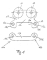
- Fig. 1 is an example of a tarpaulin roller used for moving sliding tarpaulins in curtainsiders.
- the invention is not limited to tarpaulin rollers, but generally includes support members for the storage of movable elements of a commercial vehicle body, the invention is particularly advantageous in tarpaulin rollers.
- the tarpaulin roller two rollers 10 (tandem roller) on. It is possible to equip the tarpaulin roller with only one roller or with more than two roles.
- a double tandem roller with four rollers is possible.
- the two rollers 10 are connected to a mounting plate 11 and rotatably supported.
- the two rollers 10 are arranged in a mounting position in the upper region of the mounting plate 11.
- the mounting plate 11 has an opening 12 in a lower position in the installed position.
- the opening 12 serves as in Fig. 2 shown for holding a belt loop 13, which is pulled through the opening 12.
- the opening 12 is arranged substantially horizontally and elongated, wherein the length of the opening 12 corresponds approximately to the width of the belt loop 13 and is slightly longer.
- the mounting plate 11 in the region of the opening 12 is divisible, in particular horizontally divisible. This means that the opening 12 in the split state ( Fig. 1 ) is accessible for removing or attaching the belt loop.
- this has an upper part 11a and a lower part 11b.
- the two rollers 10 are attached to the upper part 11a and protrude slightly beyond the circumference of the upper part 11a addition. Another arrangement of the rollers 10 or a single roller on the upper part 11a is possible.
- the lower part 11b forms together with the upper part 11a an opening 12 for the belt loop 13 (FIG. Fig. 2 ).
- the upper limit of the opening 12 in the installation position is formed by the upper part 11a and the lower boundary of the opening 12 through the lower part 11b.
- the upper part 11a has for this purpose an elongate, substantially in the vehicle longitudinal direction extending recess 12a, which is open at the bottom (in the disassembled state). Laterally, the recess 12a is bounded by two eye-shaped projections or two eyes, which extend in the installed position downwards. In the two eye-shaped projections 12b, 12c each have a bore 12d is provided, which serves for fastening of the lower part 11b.
- the lower part 11b extends parallel to the upper part 11a.
- two eyes 11c, 11d are provided with corresponding bores, which are in the assembled state with the two holes 12d of the eye-shaped projections 12b, 12c on the upper part 11a are aligned.
- the lower part is detachably connected by mechanical connecting means 19 with the upper part 11a.
- the connecting means 19 are rivets, in particular countersunk rivets, which are arranged in the bores of the eyes 11c, 11d or the bores 12d of the eye-shaped extensions 12b, 12c.
- Other mechanical connection means are possible.
- Fig. 2 It can also be seen that the lower part is arranged on the outer side of the tarpaulin roller in the installation position, so that the tarpaulin roller can be moved along the structure unhindered.
- the rollers 10 are attached to the inner side of the tarpaulin roller in the installation position and are in the mounted state of the tarpaulin roller in rails provided therefor, which are formed on the longitudinal beams of the structure (not shown).
- Another arrangement of the lower part 11b on the upper part 11a is possible, depending on the space requirement and execution of the longitudinal spar, in which the guide rail is designed for the scooter.
- the belt loop 13 passes through the opening 12 in the mounting plate 11 and is held securely in this.
- the belt loop 13 forms the end of a belt 13b, which is sewn to the side tarpaulin 13a.
- the side tarpaulin 13a or sliding tarpaulin over the belt 13b is securely connected to the mounting plate 11 of the tarpaulin roller.
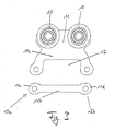
- FIGS. 3 to 6b Other embodiments, all based on the principle that the mounting plate 11 in the region of the opening 12 is divisible, are in the FIGS. 3 to 6b shown.
- the tarpaulin roller according to Fig. 3 As well as the tarpaulin scooter according to the FIGS. 1 . 2 a removable lower part, which is connected in the mounted state by mechanical connection means 19, in particular by riveting, with the upper part.
- the eyes 11c, 11d provided at the longitudinal ends 15a, 15b are formed to be axially symmetrical, whereas the eyes 11c, 11d are designed to be axially symmetrical Fig. 1 something upwards.
- the lower part according to Fig. 1 a U-shaped profile.
- the lower part according to Fig. 3 on the other hand has a bone-shaped profile.
- the tarpaulin roller according to Fig. 5 differs from the two plan scooters according to FIGS. 1 to 4 in that the lower part 11b is firmly connected to the upper part 11a. Specifically, the first longitudinal end 15a of the lower part 15b is fixedly connected to the upper part 11a. In this case, the lower part 11b and the upper part 11a in the region of the connection point form a curved connecting arm which delimits the opening 12 laterally. Another embodiment of the connection point is possible.
- the second other longitudinal end 15b of the lower part 11b, together with the upper part 11a, forms a gap 15c, which opens laterally into the opening 12.
- the gap 15c is like the opening 12 also arranged horizontally and forms an extension of the opening 12 in the horizontal direction.
- the opening for removing or for attaching the belt loop 13 is accessible.
- the lower part 11b is connected to the upper part 11a by a closure 14 which is arranged in the region of the second longitudinal end 15b of the lower part 11b.
- the closure 14 thus forms a lateral boundary of the opening 12, which is arranged opposite the connection point between the lower part 11b and the upper part 11a in the region of the first longitudinal end 15a.
- the closure is designed as a closure plate 14a, which connects the second (free) longitudinal end 15b of the lower part 11b with the upper part 11a.
- the connection of the closure plate with the lower part 11b and the upper part 11a takes place mechanically, for example by riveting 19th
- the closure plate 14a is designed so that it covers the eyes, in which the holes for the rivets 19 are provided, flush.
- FIGS. 6a, 6b are based on a similar principle as the embodiment according to Fig. 5 inasmuch as these likewise have respective lower parts 11b connected to the upper part 11a.
- connection of the lower part 11b on the upper part 11a is on the tarpaulin roller according to Fig. 5 directed.
- the lower part 11b is adapted so that it can be pivoted into an open position by the lower part 11b is bent to the side.
- the connection point in the region of the first longitudinal end 15a is designed accordingly. Due to the lateral bending of the lower part 11b, the locking elements 16 described below are decoupled, whereby the gap 15c is formed or enlarged, so that the opening 12 is easily accessible.
- the lower part 11 b is bent back so that this in the Fig. 6a, 6b shown position and latch the locking elements 16 and the upper part 11a and the lower part 11b are positively connected.
- the connection point can also be designed as a joint.
- the tarpaulin roller according to Fig. 6a differs from the tarpaulin scooter according to Fig. 5 further by the shape of the closure 14.
- the closure 14 according to Fig. 6a is designed as latching connection with locking elements 16.
- the latching elements 16 are arranged on the one hand on the lower part 11 b and on the other hand on the upper part 11 a and are in the closed position in engagement, as in Fig. 6a shown.
- the division in the region of the opening 12 takes place in accordance with the exemplary embodiment Fig. 6a in the vertical direction between an end surface of the lower part 11b and a projection 17 which is connected to the upper part 11a.
- the extension 17 forms the lateral boundary of the opening 12.
- the locking connection according to Fig. 6a a locking lug 16a, which is provided on the lower part 11b, in particular on the second free longitudinal end 15b of the lower part 11b.
- the locking lug 16a extends substantially in the horizontal direction and forms an extension of the lower part 11b.
- the detent 16a is associated with a detent opening 16b, which is formed in the extension 17 and the lower part 11b is open.
- latching elements 16 are formed so that the latching lug on the extension 17 and the latching opening in the lower part 11 b is formed. Another arrangement of the locking elements 16 is also possible.
- the tarpaulin roller according to Fig. 6b based on the tarpaulin scooter according to Fig. 6a and additionally has a securing means 18 which fixes the two locking elements 16 in the closed position.
- the securing means 18 is designed as a rivet, which is arranged in the region of the latching lug 16a and connects the lower part 11b with the upper part 11a. To open the locking connection, the rivet 18 is removed with a suitable tool, the latching connection is released and the lower part 11 b bent to the side. For mounting the lower part 11 b, after the belt loop is retracted, bent into the closed position until the latching connection locked, which is then secured by means of the rivet 18.
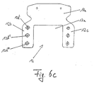
- FIG. 6c Another embodiment of a tarpaulin roller according to the invention is in Fig. 6c shown.
- This embodiment is based on the divisible tarpaulin roller according to Fig. 1 or according to Fig. 3 , This means that, as with the plan scooters according to FIGS. 1 . 3 the attachment plate 11 is completely divisible or divided in the region of the opening 12 such that the upper part 11a and the lower part 11b (in FIG Fig. 6c not shown) are separable from each other.
- the tarpaulin roller is suitable according to Fig. 6c also as a repair solution.
- the tarpaulin roller according to Fig. 6c yet another function and is designed so that the opening 12 is adjustable.
- the adjustability of the opening is achieved in that the two eye-shaped projections 12b, 12c are extended downward, ie in the vertical direction in the installed position.
- adjustment means 12 are provided for the adjustability of the opening, which in the embodiment according to Fig. 6c a plurality of superimposed holes 12d ', 12d'',12d'' include.
- the bores 12d ', 12d'',12d''' are provided symmetrically in both extensions 12b, 12c. In this case, the respectively associated holes in the extensions 12b, 12c are arranged at the same height or horizontally.
- Other adjusting means for example, vertically extending slots, in particular with different locking options, are conceivable.
- the eye-shaped extensions 12b, 12c extended such that at least two, in particular three or more holes 12d ', 12d'',12d''' are provided one above the other, in particular vertically one above the other.
- the extensions 12b, 12c limit laterally, as in the embodiments according to Fig. 1 . 3 the recess 12a and the opening 12th
- the lower part 11b (not shown) can be connected to the various holes 12d ', 12d' ', 12d' '' at different altitudes.
- the lower boundary of the opening 12 is adjustable in different positions, so that the height position of the belt loop 13 (not shown) which has passed through the opening 12 is adjustable.
- rollers in the tarpaulin roller according to Fig. 6c not shown for the sake of simplicity.
- the tarpaulin scooters according to the Figures 1 to 6b allow easy replacement without having to destroy the belt loop.
- no special repair scooters are required, which are riveted to the belt or with the side tarpaulin, but a uniform horizontally or vertically divisible tarpaulin roller is used, which can be replaced if necessary.
- the power transmission from the side tarp over the belt 13b on the tarpaulin roller is not affected by the interchangeability of the scooter.
- the tarpaulin roller according to Fig. 6c is also adaptable to different plans or tolerance deviations of tarpaulins, since the opening 12 of the tarpaulin roller is height adjustable.
- the invention also includes a commercial vehicle body and a utility vehicle with such a tarpaulin roller.
Landscapes
- Engineering & Computer Science (AREA)
- Mechanical Engineering (AREA)
- Tents Or Canopies (AREA)
- Automotive Seat Belt Assembly (AREA)
- Motorcycle And Bicycle Frame (AREA)
- Operating, Guiding And Securing Of Roll- Type Closing Members (AREA)
Abstract
Description
- Die Erfindung bezieht sich auf ein Trägerelement für bewegliche Elemente eines Nutzfahrzeugaufbaus und insbesondere auf einen Planenlaufroller für Schiebeplanen. Ein Planenlaufroller mit den Merkmalen des Oberbegriffs des Anspruchs 1 wird von der Anmelderin in den von ihr hergestellten Nutzfahrzeugaufbauten benutzt und ist bekannt.
- Dieser Planenlaufroller ist in
Fig. 7 dargestellt und weist zwei Laufrollen A auf, die an einer Platte F befestigt sind. An der Unterseite der Platte F ist eine Öffnung B vorgesehen, durch die eine Gurtschlaufe C hindurchgeführt ist. Die Gurtschlaufe C bildet das Ende eines Gurtes E, der mit einer Schiebeplane D vernäht und verklebt ist. Auf diese Weise ist die Schiebeplane D mit der Platte F des Planenlaufrollers verbunden und kann entlang des Aufbaus zum Öffnen und Schließen bewegt werden. - Der Austausch des Planenlaufrollers gemäß
Fig. 7 zu Reparaturzwecken, beispielsweise wenn eine der beiden Laufrollen A versagt, ist schwierig. Eine mögliche Reparaturlösung ist inFig. 8 dargestellt. Dabei wird ein neuer Planenlaufroller vorgesehen, dessen Platte F direkt mit dem Gurt E und der Schiebeplane D durch Nieten G verbunden wird. Aufgrund der Nietverbindung ist die Kraftübertragung von der Schiebeplane D über den Gurt E auf den Planenlaufroller ungünstig. - Der Erfindung liegt die Aufgabe zugrunde, ein Trägerelement für bewegliche Elemente eines Nutzfahrzeugaufbaus, insbesondere einen Planenlaufroller für Schiebeplanen anzugeben, der, insbesondere zu Reparaturzwecken, einfach austauschbar und/oder an verschiedene Planen bzw. an Toleranzabweichungen anpassbar ist. Ferner soll ein Nutzfahrzeugaufbau mit einem derartigen Trägerelement angegeben werden.
- Erfindungsgemäß wird diese Aufgabe durch das Trägerelement, insbesondere den Planenlaufroller gemäß Anspruch 1 bzw. durch den Nutzfahrzeugaufbau gemäß Anspruch 14 gelöst.
- Die Erfindung beruht auf dem Gedanken, ein Trägerelement für bewegliche Elemente eines Nutzfahrzeugaufbaus, insbesondere einen Planenlaufroller für Schiebeplanen anzugeben, der wenigstens eine Rolle aufweist, die mit einer Befestigungsplatte verbunden ist. Die Befestigungsplatte weist eine Öffnung zur Halterung einer Gurtschlaufe auf und ist im Bereich der Öffnung teilbar bzw. geteilt. Dies hat den Vorteil, dass die Gurtschlaufe aufgrund der im Bereich der Öffnung teilbaren Befestigungsplatte einfach vom Trägerelement bzw. vom Planenlaufroller getrennt bzw. mit diesem verbunden werden kann, ohne die Gurtschlaufe zu zerstören. Die Erfindung kann dabei als Reparaturlösung für Originallaufroller gemäß
Fig. 7 eingesetzt werden. Zum Austausch eines solchen Originallaufrollers wird dessen Befestigungsplatte aufgeschnitten und die Gurtaufnahme aus der Gurtschlaufe herausgezogen, so dass die Gurtschlaufe und der Originallaufroller voneinander getrennt werden. Die Gurtschlaufe wird dabei nicht zerstört, sondern bleibt erhalten. Dann wird der erfindungsgemäße Planenlaufroller mittels der im Bereich der Öffnung teilbaren bzw. geteilten Befestigungsplatte in die Gurtschlaufe eingezogen und befestigt. Die Gurtschlaufe bleibt somit nach erfolgter Reparatur im Originalzustand erhalten. - Die günstige Kraftübertragung von der Schiebeplane über den Gurt bzw. allgemein vom beweglichen Element des Aufbaus auf den Planenlaufroller bzw. das Trägerelement wird bei der Erfindung beibehalten, da sich an der Halterung der Gurtschlaufe, zumindest was die Kontaktfläche zwischen der Befestigungsplatte und der Gurtschlaufe angeht, nichts ändert.
- Evt. nachfolgende Reparaturmaßnahmen am erfindungsgemäßen Planenlaufroller erleichtern sich aufgrund der teilbaren Befestigungsplatte, da der erfindungsgemäße Planenlaufroller im Gegensatz zum Originallaufroller für den Austausch nicht aufgeschnitten werden muss. Es ist auch denkbar, den erfindungsgemäßen Planenlaufroller im Neuzustand der Plane als Originalteil einzusetzen, um die Reparaturfreundlichkeit zu verbessern.
- Bei einer bevorzugten Ausführungsform weist die Befestigungsplatte ein Oberteil und ein Unterteil auf, wobei die wenigstens eine Rolle am Oberteil befestigt ist und das Unterteil zusammen mit dem Oberteil die Öffnung für die Gurtschlaufe bildet. Mittels des Oberteils und des Unterteils wird auf besonders einfache Weise die im Bereich der Öffnung teilbare Befestigungsplatte realisiert.
- Das Unterteil kann bügelförmig ausgebildet sein, wodurch eine einfache Handhabung des Trägerelementes bei der Reparatur ermöglicht wird.
- Das Unterteil kann bei einer weiteren Ausführungsform durch mechanische Verbindungsmittel mit dem Oberteil verbunden sein, insbesondere abnehmbar verbunden sein. Wenn ein Originalteil durch das Trägerelement bzw. den Planenlaufroller ausgetauscht werden soll, wird die Gurtschlaufe mit der im Bereich der Öffnung geteilten Befestigungsplatte verbunden, wobei das Unterteil und das Oberteil im Eingriff mit der Gurtschlaufe zusammengefügt und durch die mechanischen Verbindungsmittel verbunden werden. Für einen nachfolgenden Austausch des Planenlaufrollers werden die mechanischen Verbindungsmittel gelöst und das Unterteil vom Oberteil abgenommen. Damit ist die Öffnung zugänglich und die Gurtschlaufe kann aus der Öffnung entfernt werden. Diese Ausführungsform zeichnet sich durch eine einfache Bedienbarkeit aus und ist robust.
- Bei einer alternativen Ausführungsform ist ein erstes Längsende des Unterteils fest mit dem Oberteil verbunden. Ein zweites Längsende bildet mit dem Oberteil einen Spalt. Dies hat den Vorteil, dass das Unterteil bei der Montage und Demontage des Trägerelements bzw. Planenlaufrollers am Oberteil verbleibt, so dass das Bauteil einfach zu handhaben ist. Die Entfernung bzw. Anbringung der Gurtschlaufe erfolgt durch den Spalt zwischen dem zweiten Längsende des Unterteils und dem Oberteil, wodurch die Öffnung in der Befestigungsplatte für die Gurtschlaufe zugänglich ist.
- Dabei kann vorgesehen sein, dass das Unterteil, insbesondere durch Biegen in eine Offenstellung und eine Schließstellung bewegbar ist. Dadurch wird beim Austauschen des Trägerelements bzw. Planlaufrollers die Öffnung zugänglich.
- Zur Sicherung der Gurtschlaufe in der Öffnung der Befestigungsplatte ist vorteilhafterweise ein Verschluss vorgesehen, der das Oberteil und das Unterteil im Bereich des zweiten Längsendes verbindet.
- Der Verschluss kann eine Verschlussplatte aufweisen, die mit dem Längsende des Unterteils und mit dem Oberteil verbindbar oder verbunden ist. Zum Öffnen des Trägerelements bzw. des Planenlaufrollers wird die Verschlussplatte entfernt, wodurch die Öffnung zugänglich wird. Nach erfolgtem Austausch wird die Öffnung mittels der Verschlussplatte wieder verschlossen, so dass die Gurtschlaufe in der Öffnung der Befestigungsplatte sicher gehalten ist.
- Der Verschluss kann Rastelemente umfassen, die am Unterteil und am Oberteil angeordnet und in der Schließstellung im Eingriff sind. Diese Ausführungsform ist besonders geeignet im Zusammenhang mit dem Unterteil, das in eine Schließ- und Offenstellung bewegbar ist, derart, dass sich in der Offenstellung ein Öffnungswinkel ergibt, der ausreicht, um die Gurtschlaufe zu entfernen. In der Schließstellung wird der Winkel wieder auf 0 Grad zurückgeführt, so dass die Teile wieder formschlüssig verbunden sind.
- Dabei kann das zweite Längsende des Unterteils eine Rastnase aufweisen, die in der Schließstellung in eine Rastöffnung eingreift, die in einem Fortsatz ausgebildet ist, der mit dem Oberteil verbunden ist. Dadurch wird auf einfache Weise die Rastverbindung zwischen dem Oberteil und dem Unterteil realisiert. Dabei kann vorgesehen sein, dass die Rastelemente in der Schließstellung mit einem Sicherungsmittel, insbesondere einem Niet, fixierbar sind. Dadurch wird verhindert, dass die Rastverbindung ungewollt gelöst wird.
- Bei einer weiteren bevorzugten Ausführungsform ist die Öffnung zur Halterung der Gurtschlaufe verstellbar, insbesondere höhenverstellbar. Durch die Verstellbarkeit, insbesondere die Höhenverstellbarkeit der Öffnung wird eine Änderung der Ortslage der Gurtschlaufe erreicht, die durch die Öffnung hindurchgeschlauft ist. Die Öffnung bzw. allgemein das Trägerelement sind somit an verschiedene Planen anpassbar. Beispielsweise ist es mit der verstellbaren Öffnung möglich, Toleranzabweichungen bei Planen zu kompensieren, die über die Verstellmöglichkeiten der Spannelemente an der Planenunterkante hinausgehen. Außerdem wird durch die verstellbare Öffnung das Nachjustieren der Plane ermöglicht, wenn sich der jeweilige Gurt im Gebrauch längt. Durch Verstellen der Öffnung kann die Längung des Gurtes nachträglich kompensiert werden.
- Dabei kann vorgesehen sein, dass das Unterteil mit dem Oberteil in verschiedenen Höhenlagen verbindbar ist. Diese Ausführungsform bietet eine einfache Möglichkeit, die Verstellbarkeit der Öffnung zur Halterung der Gurtschlaufe zu realisieren. Die Höhenlage des Unterteils bestimmt dabei die Höhenlage der Gurtschlaufe und somit den Abstand zwischen der Gurtschlaufe und dem Außenrahmen des Aufbaus.
- Die Erfindung umfasst ferner einen Nutzfahrzeugaufbau mit einem Trägerelement bzw. mit einem Planenlaufroller gemäß einem der vorstehend genannten Ausführungsbeispiele bzw. gemäß einer Kombination der vorstehend genannten Ausführungsbeispiele.
- Die Erfindung wird nachfolgend anhand von Ausführungsbeispielen unter Bezug auf die beigefügten schematischen Zeichnungen näher erläutert. In diesen zeigen:
- Fig. 1
- eine Seitenansicht eines Planenlaufrollers nach einem erfindungsgemäßen Ausführungsbeispiel mit abnehmbarem Unterteil;
- Fig. 2
- eine Seitenansicht des Planenlaufrollers gemäß
Fig. 1 , der mit einer Schiebeplane verbunden ist; - Fig. 3
- eine Seitenansicht eines Planenlaufrollers nach einem weiteren erfindungsgemäßen Ausführungsbeispiel mit abnehmbarem Unterteil;
- Fig. 4
- eine perspektivische Ansicht des Planenlaufrollers gemäß
Fig. 3 ; - Fig. 5
- eine Seitenansicht eines Planenlaufrollers nach einem weiteren erfindungsgemäßen Ausführungsbeispiel, bei dem das Unterteil einseitig fest mit dem Oberteil verbunden ist;
- Fig. 6a
- eine Seitenansicht eines Planenlaufrollers nach einem weiteren erfindungsgemäßen Ausführungsbeispiel, bei dem das Unterteil mit dem Oberteil durch eine Rastverbindung verschließbar ist;
- Fig. 6b
- eine Seitenansicht eines Planenlaufrollers nach einem weiteren erfindungsgemäßen Ausführungsbeispiel mit einem modifizierten Rastverschluss;
- Fig. 6c
- eine Seitenansicht eines Planenlaufrollers nach einem weiteren erfindungsgemäßen Ausführungsbeispiel, bei dem die Öffnung zur Halterung der Gurtschlaufe verstellbar ist;
- Fig. 7
- eine Seitenansicht eines Planenlaufrollers nach dem Stand der Technik; und
- Fig. 8
- eine Seitenansicht eines Planenlaufrollers gemäß einer bekannten Reparaturlösung.
-
Fig. 1 stellt ein Beispiel für einen Planenlaufroller dar, der zum Verschieben von Schiebeplanen bei Seitenplanenfahrzeugen bzw. Curtainsidern zum Einsatz kommt. Die Erfindung ist nicht auf Planenlaufroller beschränkt, sondern umfasst allgemein Trägerelemente zur Lagerung von beweglichen Elementen eines Nutzfahrzeugaufbaus, wobei die Erfindung bei Planenlaufrollern besonders vorteilhaft ist. Wie inFig. 1 zu erkennen, weist der Planenlaufroller zwei Rollen 10 (Tandemroller) auf. Es ist möglich, den Planenlaufroller mit nur einer Rolle oder auch mit mehr als zwei Rollen auszustatten. Je nach Ausführung des Holms, in dem der Planenlaufroller geführt ist, ist bspw. ein Doppeltandemroller mit vier Rollen möglich. - Die beiden Rollen 10 sind mit einer Befestigungsplatte 11 verbunden und drehbar gelagert. Dabei sind die beiden Rollen 10 in einem in der Einbaulage oberen Bereich der Befestigungsplatte 11 angeordnet. Die Befestigungsplatte 11 weist in einem in der Einbaulage unteren Bereich eine Öffnung 12 auf. Die Öffnung 12 dient, wie in
Fig. 2 dargestellt, zur Halterung einer Gurtschlaufe 13, die durch die Öffnung 12 hindurchgezogen ist. Für die Aufnahme der Gurtschlaufe 13 ist die Öffnung 12 im Wesentlichen horizontal angeordnet und länglich ausgebildet, wobei die Länge der Öffnung 12 in etwa der Breite der Gurtschlaufe 13 entspricht bzw. etwas länger ist. - Wie in
Fig. 1 gut zu erkennen, ist die Befestigungsplatte 11 im Bereich der Öffnung 12 teilbar, insbesondere horizontal teilbar. Dies bedeutet, dass die Öffnung 12 im geteilten Zustand (Fig. 1 ) zum Entfernen bzw. Anbringen der Gurtschlaufe zugänglich ist. Für die Teilbarkeit der Befestigungsplatte 11 im Bereich der Öffnung 12 weist diese ein Oberteil 11a und ein Unterteil 11b auf. Die beiden Rollen 10 sind am Oberteil 11a befestigt und ragen dabei etwas über den Umfang des Oberteils 11a hinaus. Eine andere Anordnung der Rollen 10 bzw. einer einzigen Rolle am Oberteil 11a ist möglich. Im montierten Zustand bildet das Unterteil 11b zusammen mit dem Oberteil 11a eine Öffnung 12 für die Gurtschlaufe 13 (Fig. 2 ). Dabei wird die in der Einbaulage obere Begrenzung der Öffnung 12 durch das Oberteil 11a und die untere Begrenzung der Öffnung 12 durch das Unterteil 11b gebildet. Das Oberteil 11a weist dazu eine längliche, sich im Wesentlichen in Fahrzeuglängsrichtung erstreckende Ausnehmung 12a auf, die nach unten hin (im demontierten Zustand) offen ist. Seitlich ist die Ausnehmung 12a durch zwei ösenförmige Fortsätze bzw. zwei Augen begrenzt, die sich in der Einbaulage nach unten erstrecken. In den beiden ösenförmigen Fortsätzen 12b, 12c ist jeweils eine Bohrung 12d vorgesehen, die zur Befestigung des Unterteils 11b dient. - Das Unterteil 11b erstreckt sich parallel zum Oberteil 11a. Wie in
Fig. 1 zu erkennen, ist das Unterteil 11b bügelförmig bzw. in Form eines Bügels ausgebildet und dient als Längsabschlussteil der Befestigungsplatte 11. An den beiden Längsenden 15a, 15b des Unterteils 11b bzw. des Längsabschlussteils sind zwei Augen 11c, 11d mit entsprechenden Bohrungen vorgesehen, die im montierten Zustand mit den beiden Bohrungen 12d der ösenförmigen Fortsätze 12b, 12c am Oberteil 11a fluchten. - Wie in
Fig. 2 dargestellt, ist das Unterteil durch mechanische Verbindungsmittel 19 mit dem Oberteil 11a abnehmbar verbunden. Bei den Verbindungsmitteln 19 handelt es sich um Nieten, insbesondere um Senknieten, die in den Bohrungen der Augen 11c, 11d bzw. den Bohrungen 12d der ösenförmigen Fortsätze 12b, 12c angeordnet sind. Andere mechanische Verbindungsmittel sind möglich. - In
Fig. 2 ist ferner zu erkennen, dass das Unterteil auf der in Einbaulage äußeren Seite des Planenlaufrollers angeordnet ist, damit der Planenlaufroller ungehindert am Aufbau entlang bewegt werden kann. Die Rollen 10 sind an der in der Einbaulage inneren Seite des Planenlaufrollers befestigt und befinden sich im montierten Zustand des Planenlaufrollers in dafür vorgesehenen Schienen, die an den Längsholmen des Aufbaus ausgebildet sind (nicht dargestellt). Eine andere Anordnung des Unterteils 11b am Oberteil 11a ist möglich, je nach Platzbedarf und Ausführung des Längsholmes, in dem die Führungsschiene für den Roller ausgebildet ist. - Im verbundenen Zustand (
Fig. 2 ) durchgreift die Gurtschlaufe 13 die Öffnung 12 in der Befestigungsplatte 11 und ist in dieser sicher gehalten. Die Gurtschlaufe 13 bildet dabei das Ende eines Gurtes 13b, der mit der Seitenplane 13a vernäht ist. Auf diese Weise ist die Seitenplane 13a bzw. Schiebeplane über den Gurt 13b sicher mit der Befestigungsplatte 11 des Planenlaufrollers verbunden. - Der Austausch des Planenlaufrollers gemäß
Fig. 7 erfolgt dadurch, dass die Gurtschlaufe 13 freigeschnitten, bzw. anderweitig vom Planenlaufroller entfernt wird, ohne dabei die Gurtschlaufe zu zerstören. Die freie Gurtschlaufe 13 wird dann mit der geteilten Befestigungsplatte 11 des Planenlaufrollers gemäßFig. 2 verbunden. Dazu wird das Unterteil 11b in die Gurtschlaufe 13 eingeführt und mit dem Oberteil 11a durch die mechanischen Verbindungsmittel 19 bzw. Nieten verbunden. Die inFig. 2 dargestellte Nietverbindung ermöglicht eine sichere und feste Verbindung des Unterteils 11b mit dem Oberteil 11a, die überdies zu nachfolgenden Reparaturzwecken relativ einfach mittels geeigneter, an sich bekannter Werkzeuge gelöst werden kann, so dass das Unterteil 11b vom Oberteil 11a bei Bedarf wieder abgenommen werden kann. - Weitere Ausführungsbeispiele, die alle auf dem Prinzip beruhen, dass die Befestigungsplatte 11 im Bereich der Öffnung 12 teilbar ist, sind in den
Figuren 3 bis 6b dargestellt. - Der Planenlaufroller gemäß
Fig. 3 weist ebenso wie der Planenlaufroller gemäß denFiguren 1 ,2 ein abnehmbares Unterteil auf, das im montierten Zustand durch mechanische Verbindungsmittel 19, insbesondere durch Nieten, mit dem Oberteil verbunden ist. Im Unterschied zu dem Unterteil gemäßFig. 1 sind die an den Längsenden 15a, 15b vorgesehenen Augen 11c, 11d achsensymmetrisch ausgebildet, wohingegen die Augen 11c, 11d gemäßFig. 1 etwas nach oben gerichtet sind. Dadurch weist das Unterteil gemäßFig. 1 ein U-förmiges Profil auf. Das Unterteil gemäßFig. 3 weist dagegen ein knochenförmiges Profil auf. - Der Planenlaufroller gemäß
Fig. 5 unterscheidet sich von den beiden Planenlaufrollern gemäßFiguren 1 bis 4 dadurch, dass das Unterteil 11b fest mit dem Oberteil 11a verbunden ist. Konkret ist das erste Längsende 15a des Unterteils 15b fest mit dem Oberteil 11a verbunden. Dabei bilden das Unterteil 11b und das Oberteil 11a im Bereich der Verbindungsstelle einen gekrümmten Verbindungsarm, der die Öffnung 12 seitlich begrenzt. Eine andere Ausgestaltung der Verbindungsstelle ist möglich. Das zweite andere Längsende 15b des Unterteils 11b bildet zusammen mit dem Oberteil 11a einen Spalt 15c, der in die Öffnung 12 seitlich mündet. Der Spalt 15c ist wie die Öffnung 12 ebenfalls horizontal angeordnet und bildet eine Verlängerung der Öffnung 12 in horizontaler Richtung. - Dadurch ist die Öffnung zum Entfernen bzw. zum Anbringen der Gurtschlaufe 13 zugänglich.
- Das Unterteil 11b ist mit dem Oberteil 11a durch einen Verschluss 14 verbunden, der im Bereich des zweiten Längsendes 15b des Unterteils 11b angeordnet ist. Der Verschluss 14 bildet somit eine seitliche Begrenzung der Öffnung 12, die der Verbindungsstelle zwischen dem Unterteil 11b und dem Oberteil 11a im Bereich des ersten Längsendes 15a gegenüber angeordnet ist.
- Bei dem Ausführungsbeispiel gemäß
Fig. 5 ist der Verschluss als Verschlussplatte 14a ausgeführt, die das zweite (freie) Längsende 15b des Unterteils 11b mit dem Oberteil 11a verbindet. Die Verbindung der Verschlussplatte mit dem Unterteil 11b und dem Oberteil 11a erfolgt mechanisch, beispielsweise durch Nieten 19. - Die Verschlussplatte 14a ist dabei so gestaltet, dass diese die Augen, in denen die Bohrungen für die Nieten 19 vorgesehen sind, bündig überdeckt.
- Die beiden Ausführungsbeispiele gemäß
Figuren 6a, 6b basieren auf einem ähnlichen Prinzip, wie das Ausführungsbeispiel gemäßFig. 5 , insofern als diese ebenfalls jeweils fest mit dem Oberteil 11a verbundene Unterteile 11b aufweisen. Im Hinblick auf die Beschreibung der Anbindung des Unterteils 11b am Oberteil 11a wird auf den Planenlaufroller gemäßFig. 5 verwiesen. - Um die Öffnung 12 für die Gurtschlaufe 13 zugänglich zu machen, ist das Unterteil 11b so angepasst, dass dieses in eine Offenstellung verschwenkt werden kann, indem das Unterteil 11b zur Seite hin aufgebogen wird. Dazu ist die Verbindungsstelle im Bereich des ersten Längsendes 15a entsprechend ausgelegt. Durch das seitliche Verbiegen des Unterteils 11b werden die nachfolgend beschriebenen Rastelemente 16 entkoppelt, wodurch der Spalt 15c gebildet bzw. vergrößert wird, so dass die Öffnung 12 gut zugänglich ist. Zum Verschließen der Öffnung 12 wird das Unterteil 11b wieder zurück gebogen, so dass dieses die in den
Fig. 6a, 6b dargestellte Stellung einnimmt und die Rastelemente 16 verrasten bzw. das Oberteil 11a und das Unterteil 11b formschlüssig verbunden sind. Die Verbindungsstelle kann auch als Gelenk ausgeführt sein. - Der Planenlaufroller gemäß
Fig. 6a unterscheidet sich vom Planenlaufroller gemäßFig. 5 ferner durch die Form des Verschlusses 14. Der Verschluss 14 gemäßFig. 6a ist als Rastverbindung mit Rastelementen 16 ausgeführt. Die Rastelemente 16 sind einerseits am Unterteil 11b und andererseits am Oberteil 11a angeordnet und befinden sich in der Schließstellung im Eingriff, wie inFig. 6a dargestellt. Die Teilung im Bereich der Öffnung 12 erfolgt bei dem Ausführungsbeispiel gemäßFig. 6a in vertikaler Richtung zwischen einer Stirnfläche des Unterteils 11b und einem Fortsatz 17, der mit dem Oberteil 11a verbunden ist. Der Fortsatz 17 bildet dabei die seitliche Begrenzung der Öffnung 12. Konkret umfasst die Rastverbindung gemäßFig. 6a eine Rastnase 16a, die am Unterteil 11b, insbesondere am zweiten freien Längsende 15b des Unterteils 11b vorgesehen ist. - Die Rastnase 16a erstreckt sich im Wesentlichen in horizontaler Richtung und bildet eine Verlängerung des Unterteils 11b. Der Rastnase 16a ist eine Rastöffnung 16b zugeordnet, die im Fortsatz 17 ausgebildet und zum Unterteil 11b hin geöffnet ist.
- Es ist auch möglich, dass die Rastelemente 16 so ausgebildet sind, dass die Rastnase am Fortsatz 17 und die Rastöffnung im Unterteil 11b ausgebildet ist. Eine andere Anordnung der Rastelemente 16 ist ebenfalls möglich.
- Der Planenlaufroller gemäß
Fig. 6b basiert auf dem Planenlaufroller gemäßFig. 6a und weist zusätzlich ein Sicherungsmittel 18 auf, das die beiden Rastelemente 16 in der Schließstellung fixiert. Das Sicherungsmittel 18 ist als Niet ausgeführt, der im Bereich der Rastnase 16a angeordnet ist und das Unterteil 11b mit dem Oberteil 11a verbindet. Zum Öffnen der Rastverbindung, wird der Niet 18 mit einem geeigneten Werkzeug entfernt, die Rastverbindung gelöst und das Unterteil 11b zur Seite hin gebogen. Zum Montieren wird das Unterteil 11b, nachdem die Gurtschlaufe eingezogen ist, in die Schließstellung gebogen, bis die Rastverbindung verrastet, die dann mittels des Niet 18 gesichert wird. - Ein weiteres Ausführungsbeispiel eines erfindungsgemäßen Planenlaufrollers ist in
Fig. 6c dargestellt. Dieses Ausführungsbeispiel basiert auf dem teilbaren Planenlaufroller gemäßFig. 1 bzw. gemäßFig. 3 . Das bedeutet, dass, wie bei den Planenlaufrollern gemäßFiguren 1 ,3 die Befestigungsplatte 11 im Bereich der Öffnung 12 vollständig teilbar bzw. geteilt ist derart, dass das Oberteil 11a und das Unterteil 11b (inFig. 6c nicht dargestellt) voneinander trennbar sind. Insofern eignet sich der Planenlaufroller gemäßFig. 6c ebenfalls als Reparaturlösung. Darüber hinaus weist der Planenlaufroller gemäßFig. 6c noch eine weitere Funktion auf und ist so ausgestaltet, dass die Öffnung 12 verstellbar ist. Die Verstellbarkeit der Öffnung wird dadurch erreicht, dass die beiden ösenförmigen Fortsätze 12b, 12c nach unten, d.h. in vertikaler Richtung in der Einbaulage verlängert sind. Im Bereich der Öffnung 12 bzw. der Ausnehmung 12a im Oberteil 11a sind für die Verstellbarkeit der Öffnung 12 Verstellmittel vorgesehen, die bei dem Ausführungsbeispiel gemäßFig. 6c mehrere übereinander angeordnete Bohrungen 12d', 12d'', 12d''' umfassen. Die Bohrungen 12d', 12d'', 12d''' sind symmetrisch in beiden Fortsätze 12b, 12c vorgesehen. Dabei sind die jeweils zugehörigen Bohrungen in den Fortsätze 12b, 12c auf gleicher Höhe bzw. horizontal angeordnet. Andere Verstellmittel, beispielsweise vertikal sich erstreckende Langlöcher, insbesondere mit verschiedenen Rastmöglichkeiten, sind denkbar. - Bei dem Planenlaufroller gemäß
Fig. 6c sind die ösenförmigen Fortsätze 12b, 12c derart verlängert, dass wenigstens zwei, insbesondere drei oder mehr Bohrungen 12d', 12d'', 12d''' übereinander, insbesondere vertikal übereinander vorgesehen sind. Die Fortsätze 12b, 12c begrenzen seitlich dabei, wie bei den Ausführungsbeispielen gemäßFig. 1 ,3 die Ausnehmung 12a bzw. die Öffnung 12. - Das Unterteil 11b (nicht dargestellt) kann mit den verschiedenen Bohrungen 12d', 12d'', 12d''' in verschiedenen Höhenlagen verbunden werden. Dadurch ist die untere Begrenzung der Öffnung 12 in verschiedenen Positionen einstellbar, so dass die Höhenlage der durch die Öffnung 12 hindurchgeschlauften Gurtschlaufe 13 (nicht dargestellt) verstellbar ist.
- Dies hat den Vorteil, dass beispielsweise Toleranzabweichungen in der Planenhöhe durch Verstellen der Öffnung 12 kompensiert werden können. Der Planenlaufroller gemäß
Fig. 6c eignet sich für den Einbau als Originalroller. Wenn einzelne Gurte durch den Gebrauch übermäßig gelängt werden, kann der Planenlaufroller gemäßFig. 6c auch als Reparaturlösung eingesetzt werden, um die Längung des jeweiligen Gurtes auszugleichen. - Ergänzend ist anzumerken, dass die Rollen bei dem Planenlaufroller gemäß
Fig. 6c aus Gründen der Einfachheit nicht dargestellt sind. - Die Planenlaufroller gemäß den
Figuren 1 bis 6b ermöglichen einen einfachen Austausch, ohne dass dabei die Gurtschlaufe zerstört werden muss. Außerdem sind keine speziellen Reparaturlaufroller erforderlich, die mit dem Gurt bzw. mit der Seitenplane vernietet werden, sondern ein einheitlicher horizontal oder vertikal teilbarer Planenlaufroller wird eingesetzt, der bei Bedarf ausgetauscht werden kann. Die Kraftübertragung von der Seitenplane über den Gurt 13b auf den Planenlaufroller wird durch die Austauschbarkeit des Rollers nicht beeinträchtigt. Der Planenlaufroller gemäßFig. 6c ist überdies an verschiedene Planen bzw. Toleranzabweichungen von Planen anpassbar, da die Öffnung 12 des Planenlaufrollers höhenverstellbar ist. - Die Erfindung umfasst auch einen Nutzfahrzeugaufbau und ein Nutzfahrzeug mit einem derartigen Planenlaufroller.
-
- 10
- Rolle
- 11
- Befestigungsplatte
- 11a
- Oberteil
- 11b
- Unterteil
- 11c, 11d
- Augen
- 12
- Öffnung
- 12a
- Ausnehmung
- 12b, 12c
- ösenförmige Fortsätze
- 12d
- Bohrung
- 13
- Gurtschlaufe
- 13a
- Seitenplane
- 13b
- Gurt
- 14
- Verschluss
- 14a
- Verschlussplatte
- 15a, 15b
- Längsenden
- 15c
- Spalt
- 16
- Rastelemente
- 16a
- Rastnase
- 16b
- Rastöffnung
- 17
- Fortsatz
- 18
- Sicherungsteil
- 19
- Verbindungsmittel
Claims (14)
- Trägerelement für bewegliche Elemente eines Nutzfahrzeugaufbaus, insbesondere Planenlaufroller für Schiebeplanen (13a) mit wenigstens einer Rolle (10), die mit einer Befestigungsplatte (11) verbunden ist, wobei die Befestigungsplatte (11) eine Öffnung (12) zur Halterung einer Gurtschlaufe (13) aufweist,
dadurch gekennzeichnet, dass
die Befestigungsplatte (11) im Bereich der Öffnung (12) teilbar oder geteilt ist. - Trägerelement, insbesondere Planenlaufroller nach Anspruch 1,
dadurch gekennzeichnet, dass
die Befestigungsplatte (11) ein Oberteil (11a) und ein Unterteil (11b) aufweist, wobei die wenigstens eine Rolle (10) am Oberteil (11a) befestigt ist und das Unterteil (11b) zusammen mit dem Oberteil (11a) die Öffnung (12) für die Gurtschlaufe (13) bildet. - Trägerelement, insbesondere Planenlaufroller nach Anspruch 2,
dadurch gekennzeichnet, dass
das Unterteil (11b) bügelförmig ausgebildet ist. - Trägerelement, insbesondere Planenlaufroller nach Anspruch 2 oder 3,
dadurch gekennzeichnet, dass
das Unterteil (11b) durch mechanische Verbindungsmittel (19) mit dem Oberteil (11a) verbunden, insbesondere abnehmbar verbunden ist. - Trägerelement, insbesondere Planenlaufroller nach Anspruch 2 oder 3,
dadurch gekennzeichnet, dass
ein erstes Längsende (15a) des Unterteils (11b) fest mit dem Oberteil (11a) verbunden ist und ein zweites Längsende (15b) einen Spalt (15c) mit dem Oberteil (11a) bildet. - Trägerelement, insbesondere Planenlaufroller nach Anspruch 2 oder 3,
dadurch gekennzeichnet, dass
das Unterteil (11b), insbesondere durch Aufbiegen, in eine Offenstellung und in eine Schließstellung bewegbar ist. - Trägerelement, insbesondere Planenlaufroller nach Anspruch 5 oder 6,
dadurch gekennzeichnet, dass
ein Verschluss (14) das Oberteil (11a) und das Unterteil (11b) im Bereich des zweiten Längsendes (15b) verbindet. - Trägerelement, insbesondere Planenlaufroller nach Anspruch 7,
dadurch gekennzeichnet, dass
der Verschluss (14) eine Verschlussplatte (14a) aufweist, die mit dem zweiten Längsende (15b) des Unterteils (11b) und mit dem Oberteil (11a) verbindbar oder verbunden ist. - Trägerelement, insbesondere Planenlaufroller nach Anspruch 7,
dadurch gekennzeichnet, dass
der Verschluss (14) Rastelemente (16) umfasst, die am Unterteil (11b) und am Oberteil (11a) angeordnet und in der Schließstellung im Eingriff sind. - Trägerelement, insbesondere Planenlaufroller nach Anspruch 9,
dadurch gekennzeichnet, dass
das zweite Längsende (15b) des Unterteils (11b) eine Rastnase (16a) aufweist, die in der Schließstellung in eine Rastöffnung (16b) eingreift, die in einem Fortsatz (16) ausgebildet ist, der mit dem Oberteil (11a) verbunden ist. - Trägerelement, insbesondere Planenlaufroller nach Anspruch 9 oder 10,
dadurch gekennzeichnet, dass
die Rastelemente (16) in der Schließstellung mit einem Sicherungsmittel (18), insbesondere einem Niet, fixierbar sind. - Trägerelement, insbesondere Planenlaufroller nach wenigstens einem der Ansprüche 1 bis 9,
dadurch gekennzeichnet, dass
die Öffnung (12) zur Halterung der Gurtschlaufe (13) verstellbar, insbesondere höhenverstellbar ist. - Trägerelement, insbesondere Planenlaufroller nach Anspruch 12,
dadurch gekennzeichnet, dass
das Unterteil (11b) mit dem Oberteil (11a) in verschiedenen Höhenlagen verbindbar ist. - Nutzfahrzeugaufbau mit einem Trägerelement, insbesondere einem Planenlaufroller, gemäß einem der Ansprüche 1 bis 13.
Priority Applications (1)
| Application Number | Priority Date | Filing Date | Title |
|---|---|---|---|
| PL09007243T PL2130704T3 (pl) | 2008-06-06 | 2009-05-29 | Element nośny do ruchomych elementów nadwozia pojazdu użytkowego i nadwozie pojazdu użytkowego z tego rodzaju elementem nośnym |
Applications Claiming Priority (2)
| Application Number | Priority Date | Filing Date | Title |
|---|---|---|---|
| DE202008007592 | 2008-06-06 | ||
| DE202008007930U DE202008007930U1 (de) | 2008-06-06 | 2008-06-13 | Trägerelement für bewegliche Elemente eines Nutzfahrzeugaufbaus und Nutzfahrzeugaufbau mit einem derartigen Trägerelement |
Publications (3)
| Publication Number | Publication Date |
|---|---|
| EP2130704A2 true EP2130704A2 (de) | 2009-12-09 |
| EP2130704A3 EP2130704A3 (de) | 2010-08-18 |
| EP2130704B1 EP2130704B1 (de) | 2014-07-02 |
Family
ID=41254283
Family Applications (1)
| Application Number | Title | Priority Date | Filing Date |
|---|---|---|---|
| EP09007243.0A Active EP2130704B1 (de) | 2008-06-06 | 2009-05-29 | Trägerelement für bewegliche Elemente eines Nutzfahrzeugaufbaus und Nutzfahrzeugaufbau mit einem derartigen Trägerelement |
Country Status (3)
| Country | Link |
|---|---|
| EP (1) | EP2130704B1 (de) |
| DE (1) | DE202008007930U1 (de) |
| PL (1) | PL2130704T3 (de) |
Families Citing this family (1)
| Publication number | Priority date | Publication date | Assignee | Title |
|---|---|---|---|---|
| AU2014253657B2 (en) * | 2013-04-18 | 2017-08-31 | Mile STANKOVIC | Collision bearing |
Family Cites Families (6)
| Publication number | Priority date | Publication date | Assignee | Title |
|---|---|---|---|---|
| GB2093099B (en) * | 1981-02-12 | 1984-08-01 | Southfields Coachworks Ltd | Side curtain assembly for goods vehicles |
| DE4436238A1 (de) * | 1994-10-11 | 1996-04-18 | Miederhoff Franz Fa | Vorrichtung zur rollbaren Aufhängung insbesondere von Seitenspannplanen von Lkw-Aufbauten |
| DE19720525C2 (de) * | 1997-02-15 | 1999-10-28 | Schmitz Anhaenger Fahrzeugbau | Plane für Lastfahrzeuge |
| DE29815741U1 (de) * | 1998-09-01 | 2000-01-05 | Edscha LKW-Schiebeverdecke GmbH, 94491 Hengersberg | Seitenplanenaufhängung an Verdecken für Nutzfahrzeuge |
| DE20022003U1 (de) * | 2000-12-27 | 2001-05-10 | Roland International B.V., Tegelen | Verdeck aus Planen für ein Fahrzeug zur Beförderung von Lasten |
| FR2842464B1 (fr) * | 2002-07-17 | 2004-10-15 | Fair Internat | Latte de renfort pour paroi souple de vehicule du genre fourgon, procede d'elaboration d'une telle paroi lattee et paroi obtenue par le procede |
-
2008
- 2008-06-13 DE DE202008007930U patent/DE202008007930U1/de not_active Expired - Lifetime
-
2009
- 2009-05-29 EP EP09007243.0A patent/EP2130704B1/de active Active
- 2009-05-29 PL PL09007243T patent/PL2130704T3/pl unknown
Non-Patent Citations (1)
| Title |
|---|
| None |
Also Published As
| Publication number | Publication date |
|---|---|
| PL2130704T3 (pl) | 2014-11-28 |
| DE202008007930U1 (de) | 2009-10-29 |
| EP2130704A3 (de) | 2010-08-18 |
| EP2130704B1 (de) | 2014-07-02 |
Similar Documents
| Publication | Publication Date | Title |
|---|---|---|
| EP2943376B1 (de) | Dachgrundträger für ein kraftfahrzeug | |
| EP1780354B1 (de) | Schiebetüranordnung für ein Kraftfahrzeug | |
| DE2532187A1 (de) | Schiebedach fuer kraftfahrzeuge | |
| EP2736762B1 (de) | Fahrzeugsitz, insbesondere kraftfahrzeugsitz | |
| DE60017190T2 (de) | Fahrzeugmontierter gepäckträger | |
| DE602005002201T2 (de) | Teleskopführung für Schubladen | |
| DE2936051C2 (de) | Hebevorrichtung für ein Kraftfahrzeug-Schiebedach | |
| EP0359962A1 (de) | Sitz, insbesondere Kraftfahrzeugsitz | |
| AT518211A2 (de) | Runge für einen nutzfahrzeug- oder anhängeraufbau | |
| DE10333781A1 (de) | Öffnungsfähiges Fahrzeugdach | |
| DE202020006041U1 (de) | Anordnung zur Führung einer Schiebetür oder Falt-Schiebetür | |
| DE102008008747A1 (de) | Schließsystem | |
| DE202021100270U1 (de) | Adaptersystem zum lösbaren Ankoppeln von Zubehör an einem Fahrzeug-Gepäckträger | |
| WO2020173990A1 (de) | Öffnungsfähiges fahrzeugdach mit einem deckel | |
| DE102017204494B4 (de) | Schiebedachsystem für ein Kraftfahrzeug | |
| EP2130704B1 (de) | Trägerelement für bewegliche Elemente eines Nutzfahrzeugaufbaus und Nutzfahrzeugaufbau mit einem derartigen Trägerelement | |
| DE102010043022A1 (de) | Sicherungsvorrichtung für ein Kraftfahrzeug | |
| EP0383003A2 (de) | Feststellvorrichtung für die Flügel von Festern, Türen od. dgl. | |
| DE10254774B4 (de) | Fahrzeugdach | |
| DE19719644C2 (de) | Windabweiseranordnung für ein Fahrzeugdach | |
| DE102017117042A1 (de) | Verschlussvorrichtung mit Verstellhebel | |
| EP1764138A1 (de) | Vorrichtung zum Positionieren einer zwei Skibindungsteile aufweisenden Skibindung auf einem Ski | |
| DE60304742T2 (de) | Spannungsvorrichtung für ein öffnungsfähiges dach eines kraftfahrzeugs | |
| DE102006061505B4 (de) | Rolloeinheit sowie korrespondierende Tragvorrichtung | |
| DE2249718C3 (de) | Schiebedach für Kraftfahrzeuge |
Legal Events
| Date | Code | Title | Description |
|---|---|---|---|
| PUAI | Public reference made under article 153(3) epc to a published international application that has entered the european phase |
Free format text: ORIGINAL CODE: 0009012 |
|
| AK | Designated contracting states |
Kind code of ref document: A2 Designated state(s): AT BE BG CH CY CZ DE DK EE ES FI FR GB GR HR HU IE IS IT LI LT LU LV MC MK MT NL NO PL PT RO SE SI SK TR |
|
| PUAL | Search report despatched |
Free format text: ORIGINAL CODE: 0009013 |
|
| AK | Designated contracting states |
Kind code of ref document: A3 Designated state(s): AT BE BG CH CY CZ DE DK EE ES FI FR GB GR HR HU IE IS IT LI LT LU LV MC MK MT NL NO PL PT RO SE SI SK TR |
|
| AX | Request for extension of the european patent |
Extension state: AL BA RS |
|
| 19U | Interruption of proceedings before grant |
Effective date: 20091030 |
|
| 19W | Proceedings resumed before grant after interruption of proceedings |
Effective date: 20101201 |
|
| 17P | Request for examination filed |
Effective date: 20110203 |
|
| RAP1 | Party data changed (applicant data changed or rights of an application transferred) |
Owner name: KOEGEL TRAILER GMBH & CO. KG |
|
| RAP1 | Party data changed (applicant data changed or rights of an application transferred) |
Owner name: KOEGEL TRAILER GMBH & CO. KG |
|
| 17Q | First examination report despatched |
Effective date: 20120703 |
|
| GRAP | Despatch of communication of intention to grant a patent |
Free format text: ORIGINAL CODE: EPIDOSNIGR1 |
|
| INTG | Intention to grant announced |
Effective date: 20131211 |
|
| GRAP | Despatch of communication of intention to grant a patent |
Free format text: ORIGINAL CODE: EPIDOSNIGR1 |
|
| GRAS | Grant fee paid |
Free format text: ORIGINAL CODE: EPIDOSNIGR3 |
|
| INTG | Intention to grant announced |
Effective date: 20140506 |
|
| GRAA | (expected) grant |
Free format text: ORIGINAL CODE: 0009210 |
|
| AK | Designated contracting states |
Kind code of ref document: B1 Designated state(s): AT BE BG CH CY CZ DE DK EE ES FI FR GB GR HR HU IE IS IT LI LT LU LV MC MK MT NL NO PL PT RO SE SI SK TR |
|
| REG | Reference to a national code |
Ref country code: GB Ref legal event code: FG4D Free format text: NOT ENGLISH |
|
| REG | Reference to a national code |
Ref country code: CH Ref legal event code: EP Ref country code: AT Ref legal event code: REF Ref document number: 675713 Country of ref document: AT Kind code of ref document: T Effective date: 20140715 |
|
| REG | Reference to a national code |
Ref country code: IE Ref legal event code: FG4D Free format text: LANGUAGE OF EP DOCUMENT: GERMAN |
|
| REG | Reference to a national code |
Ref country code: DE Ref legal event code: R096 Ref document number: 502009009596 Country of ref document: DE Effective date: 20140814 |
|
| REG | Reference to a national code |
Ref country code: NL Ref legal event code: T3 |
|
| REG | Reference to a national code |
Ref country code: PL Ref legal event code: T3 |
|
| REG | Reference to a national code |
Ref country code: LT Ref legal event code: MG4D |
|
| PG25 | Lapsed in a contracting state [announced via postgrant information from national office to epo] |
Ref country code: ES Free format text: LAPSE BECAUSE OF FAILURE TO SUBMIT A TRANSLATION OF THE DESCRIPTION OR TO PAY THE FEE WITHIN THE PRESCRIBED TIME-LIMIT Effective date: 20140702 Ref country code: PT Free format text: LAPSE BECAUSE OF FAILURE TO SUBMIT A TRANSLATION OF THE DESCRIPTION OR TO PAY THE FEE WITHIN THE PRESCRIBED TIME-LIMIT Effective date: 20141103 Ref country code: NO Free format text: LAPSE BECAUSE OF FAILURE TO SUBMIT A TRANSLATION OF THE DESCRIPTION OR TO PAY THE FEE WITHIN THE PRESCRIBED TIME-LIMIT Effective date: 20141002 Ref country code: FI Free format text: LAPSE BECAUSE OF FAILURE TO SUBMIT A TRANSLATION OF THE DESCRIPTION OR TO PAY THE FEE WITHIN THE PRESCRIBED TIME-LIMIT Effective date: 20140702 Ref country code: BG Free format text: LAPSE BECAUSE OF FAILURE TO SUBMIT A TRANSLATION OF THE DESCRIPTION OR TO PAY THE FEE WITHIN THE PRESCRIBED TIME-LIMIT Effective date: 20141002 Ref country code: LT Free format text: LAPSE BECAUSE OF FAILURE TO SUBMIT A TRANSLATION OF THE DESCRIPTION OR TO PAY THE FEE WITHIN THE PRESCRIBED TIME-LIMIT Effective date: 20140702 Ref country code: GR Free format text: LAPSE BECAUSE OF FAILURE TO SUBMIT A TRANSLATION OF THE DESCRIPTION OR TO PAY THE FEE WITHIN THE PRESCRIBED TIME-LIMIT Effective date: 20141003 Ref country code: SE Free format text: LAPSE BECAUSE OF FAILURE TO SUBMIT A TRANSLATION OF THE DESCRIPTION OR TO PAY THE FEE WITHIN THE PRESCRIBED TIME-LIMIT Effective date: 20140702 |
|
| PG25 | Lapsed in a contracting state [announced via postgrant information from national office to epo] |
Ref country code: CY Free format text: LAPSE BECAUSE OF FAILURE TO SUBMIT A TRANSLATION OF THE DESCRIPTION OR TO PAY THE FEE WITHIN THE PRESCRIBED TIME-LIMIT Effective date: 20140702 Ref country code: HR Free format text: LAPSE BECAUSE OF FAILURE TO SUBMIT A TRANSLATION OF THE DESCRIPTION OR TO PAY THE FEE WITHIN THE PRESCRIBED TIME-LIMIT Effective date: 20140702 Ref country code: LV Free format text: LAPSE BECAUSE OF FAILURE TO SUBMIT A TRANSLATION OF THE DESCRIPTION OR TO PAY THE FEE WITHIN THE PRESCRIBED TIME-LIMIT Effective date: 20140702 Ref country code: IS Free format text: LAPSE BECAUSE OF FAILURE TO SUBMIT A TRANSLATION OF THE DESCRIPTION OR TO PAY THE FEE WITHIN THE PRESCRIBED TIME-LIMIT Effective date: 20141102 |
|
| REG | Reference to a national code |
Ref country code: DE Ref legal event code: R097 Ref document number: 502009009596 Country of ref document: DE |
|
| PG25 | Lapsed in a contracting state [announced via postgrant information from national office to epo] |
Ref country code: EE Free format text: LAPSE BECAUSE OF FAILURE TO SUBMIT A TRANSLATION OF THE DESCRIPTION OR TO PAY THE FEE WITHIN THE PRESCRIBED TIME-LIMIT Effective date: 20140702 Ref country code: SK Free format text: LAPSE BECAUSE OF FAILURE TO SUBMIT A TRANSLATION OF THE DESCRIPTION OR TO PAY THE FEE WITHIN THE PRESCRIBED TIME-LIMIT Effective date: 20140702 Ref country code: IT Free format text: LAPSE BECAUSE OF FAILURE TO SUBMIT A TRANSLATION OF THE DESCRIPTION OR TO PAY THE FEE WITHIN THE PRESCRIBED TIME-LIMIT Effective date: 20140702 Ref country code: DK Free format text: LAPSE BECAUSE OF FAILURE TO SUBMIT A TRANSLATION OF THE DESCRIPTION OR TO PAY THE FEE WITHIN THE PRESCRIBED TIME-LIMIT Effective date: 20140702 Ref country code: RO Free format text: LAPSE BECAUSE OF FAILURE TO SUBMIT A TRANSLATION OF THE DESCRIPTION OR TO PAY THE FEE WITHIN THE PRESCRIBED TIME-LIMIT Effective date: 20140702 |
|
| PLBE | No opposition filed within time limit |
Free format text: ORIGINAL CODE: 0009261 |
|
| STAA | Information on the status of an ep patent application or granted ep patent |
Free format text: STATUS: NO OPPOSITION FILED WITHIN TIME LIMIT |
|
| 26N | No opposition filed |
Effective date: 20150407 |
|
| PG25 | Lapsed in a contracting state [announced via postgrant information from national office to epo] |
Ref country code: SI Free format text: LAPSE BECAUSE OF FAILURE TO SUBMIT A TRANSLATION OF THE DESCRIPTION OR TO PAY THE FEE WITHIN THE PRESCRIBED TIME-LIMIT Effective date: 20140702 |
|
| REG | Reference to a national code |
Ref country code: CH Ref legal event code: PL |
|
| GBPC | Gb: european patent ceased through non-payment of renewal fee |
Effective date: 20150529 |
|
| PG25 | Lapsed in a contracting state [announced via postgrant information from national office to epo] |
Ref country code: LU Free format text: LAPSE BECAUSE OF FAILURE TO SUBMIT A TRANSLATION OF THE DESCRIPTION OR TO PAY THE FEE WITHIN THE PRESCRIBED TIME-LIMIT Effective date: 20150529 Ref country code: LI Free format text: LAPSE BECAUSE OF NON-PAYMENT OF DUE FEES Effective date: 20150531 Ref country code: MC Free format text: LAPSE BECAUSE OF FAILURE TO SUBMIT A TRANSLATION OF THE DESCRIPTION OR TO PAY THE FEE WITHIN THE PRESCRIBED TIME-LIMIT Effective date: 20140702 Ref country code: CH Free format text: LAPSE BECAUSE OF NON-PAYMENT OF DUE FEES Effective date: 20150531 |
|
| REG | Reference to a national code |
Ref country code: IE Ref legal event code: MM4A |
|
| PG25 | Lapsed in a contracting state [announced via postgrant information from national office to epo] |
Ref country code: GB Free format text: LAPSE BECAUSE OF NON-PAYMENT OF DUE FEES Effective date: 20150529 Ref country code: IE Free format text: LAPSE BECAUSE OF NON-PAYMENT OF DUE FEES Effective date: 20150529 |
|
| REG | Reference to a national code |
Ref country code: FR Ref legal event code: PLFP Year of fee payment: 8 |
|
| PG25 | Lapsed in a contracting state [announced via postgrant information from national office to epo] |
Ref country code: MT Free format text: LAPSE BECAUSE OF FAILURE TO SUBMIT A TRANSLATION OF THE DESCRIPTION OR TO PAY THE FEE WITHIN THE PRESCRIBED TIME-LIMIT Effective date: 20140702 |
|
| REG | Reference to a national code |
Ref country code: FR Ref legal event code: PLFP Year of fee payment: 9 |
|
| PG25 | Lapsed in a contracting state [announced via postgrant information from national office to epo] |
Ref country code: HU Free format text: LAPSE BECAUSE OF FAILURE TO SUBMIT A TRANSLATION OF THE DESCRIPTION OR TO PAY THE FEE WITHIN THE PRESCRIBED TIME-LIMIT; INVALID AB INITIO Effective date: 20090529 |
|
| PG25 | Lapsed in a contracting state [announced via postgrant information from national office to epo] |
Ref country code: BE Free format text: LAPSE BECAUSE OF NON-PAYMENT OF DUE FEES Effective date: 20150531 |
|
| REG | Reference to a national code |
Ref country code: FR Ref legal event code: PLFP Year of fee payment: 10 |
|
| PG25 | Lapsed in a contracting state [announced via postgrant information from national office to epo] |
Ref country code: MK Free format text: LAPSE BECAUSE OF FAILURE TO SUBMIT A TRANSLATION OF THE DESCRIPTION OR TO PAY THE FEE WITHIN THE PRESCRIBED TIME-LIMIT Effective date: 20140702 |
|
| REG | Reference to a national code |
Ref country code: DE Ref legal event code: R082 Ref document number: 502009009596 Country of ref document: DE Representative=s name: MEISSNER BOLTE PATENTANWAELTE RECHTSANWAELTE P, DE Ref country code: DE Ref legal event code: R081 Ref document number: 502009009596 Country of ref document: DE Owner name: KOEGEL TRAILER GMBH, DE Free format text: FORMER OWNER: KOEGEL TRAILER GMBH & CO. KG, 89349 BURTENBACH, DE |
|
| REG | Reference to a national code |
Ref country code: GB Ref legal event code: 732E Free format text: REGISTERED BETWEEN 20200917 AND 20200923 |
|
| REG | Reference to a national code |
Ref country code: AT Ref legal event code: PC Ref document number: 675713 Country of ref document: AT Kind code of ref document: T Owner name: KOEGEL TRAILER GMBH, DE Effective date: 20200831 |
|
| REG | Reference to a national code |
Ref country code: NL Ref legal event code: PD Owner name: KOEGEL TRAILER GMBH; DE Free format text: DETAILS ASSIGNMENT: CHANGE OF OWNER(S), ASSIGNMENT; FORMER OWNER NAME: KOEGEL TRAILER GMBH & CO. KG Effective date: 20201217 |
|
| PGFP | Annual fee paid to national office [announced via postgrant information from national office to epo] |
Ref country code: NL Payment date: 20250526 Year of fee payment: 17 |
|
| PGFP | Annual fee paid to national office [announced via postgrant information from national office to epo] |
Ref country code: PL Payment date: 20250509 Year of fee payment: 17 |
|
| PGFP | Annual fee paid to national office [announced via postgrant information from national office to epo] |
Ref country code: FR Payment date: 20250526 Year of fee payment: 17 |
|
| PGFP | Annual fee paid to national office [announced via postgrant information from national office to epo] |
Ref country code: AT Payment date: 20250520 Year of fee payment: 17 |
|
| PGFP | Annual fee paid to national office [announced via postgrant information from national office to epo] |
Ref country code: TR Payment date: 20250509 Year of fee payment: 17 |
|
| PGFP | Annual fee paid to national office [announced via postgrant information from national office to epo] |
Ref country code: CZ Payment date: 20250520 Year of fee payment: 17 |
|
| PGFP | Annual fee paid to national office [announced via postgrant information from national office to epo] |
Ref country code: DE Payment date: 20260529 Year of fee payment: 18 |