EP2130704A2 - Elément de support pour éléments mobiles d'une structure de véhicule utilitaire et structure de véhicule utilitaire dotée d'un tel élément de support - Google Patents
Elément de support pour éléments mobiles d'une structure de véhicule utilitaire et structure de véhicule utilitaire dotée d'un tel élément de support Download PDFInfo
- Publication number
- EP2130704A2 EP2130704A2 EP09007243A EP09007243A EP2130704A2 EP 2130704 A2 EP2130704 A2 EP 2130704A2 EP 09007243 A EP09007243 A EP 09007243A EP 09007243 A EP09007243 A EP 09007243A EP 2130704 A2 EP2130704 A2 EP 2130704A2
- Authority
- EP
- European Patent Office
- Prior art keywords
- opening
- tarpaulin
- carrier element
- tarpaulin roller
- roller
- Prior art date
- Legal status (The legal status is an assumption and is not a legal conclusion. Google has not performed a legal analysis and makes no representation as to the accuracy of the status listed.)
- Granted
Links
Images





Classifications
-
- B—PERFORMING OPERATIONS; TRANSPORTING
- B60—VEHICLES IN GENERAL
- B60J—WINDOWS, WINDSCREENS, NON-FIXED ROOFS, DOORS, OR SIMILAR DEVICES FOR VEHICLES; REMOVABLE EXTERNAL PROTECTIVE COVERINGS SPECIALLY ADAPTED FOR VEHICLES
- B60J5/00—Doors
- B60J5/04—Doors arranged at the vehicle sides
- B60J5/06—Doors arranged at the vehicle sides slidable; foldable
- B60J5/062—Doors arranged at the vehicle sides slidable; foldable for utility vehicles or public transport
- B60J5/065—Doors arranged at the vehicle sides slidable; foldable for utility vehicles or public transport with non-rigid elements, e.g. side curtains
Definitions
- the invention relates to a support element for movable elements of a commercial vehicle body and in particular to a tarpaulin roller for sliding tarpaulins.
- a tarpaulin roller with the features of the preamble of claim 1 is used by the applicant in the commercial vehicle structures manufactured by it and is known.
- This tarpaulin scooter is in Fig. 7 shown and has two rollers A, which are fixed to a plate F. On the underside of the plate F, an opening B is provided, through which a belt loop C is passed. The belt loop C forms the end of a belt E, which is sewn to a sliding tarpaulin D and glued. In this way, the sliding tarpaulin D is connected to the plate F of the tarpaulin roller and can be moved along the structure for opening and closing.
- Fig. 8 Replacing the tarpaulin skid according to Fig. 7 for repair purposes, for example, if one of the two rollers A fails, is difficult.
- Fig. 8 One possible repair solution is in Fig. 8 shown.
- a new tarpaulin roller is provided, the plate F is connected directly to the belt E and the sliding tarpaulin D by rivets G. Due to the rivet connection, the power transmission from the sliding tarpaulin D via the belt E on the tarpaulin roller is unfavorable.
- the invention is based on the object, a support element for movable elements of a commercial vehicle body, in particular a tarpaulin roller for sliding tarpaulins which, in particular for repair purposes, is easily replaceable and / or adaptable to different tarpaulins or tolerance deviations. Furthermore, a commercial vehicle body to be specified with such a support element.
- this object is achieved by the carrier element, in particular the tarpaulin roller according to claim 1 or by the commercial vehicle structure according to claim 14.
- the invention is based on the idea to provide a carrier element for movable elements of a commercial vehicle body, in particular a tarpaulin roller for sliding tarpaulins, which has at least one roller which is connected to a mounting plate.
- the mounting plate has an opening for holding a belt loop and is divisible or divided in the region of the opening. This has the advantage that the belt loop can be easily separated from or connected to the carrier element or the tarpaulin roller due to the separable in the region of the opening mounting plate without destroying the belt loop.
- the invention can be used as a repair solution for original winder according to Fig. 7 be used.
- the mounting plate has an upper part and a lower part, wherein the at least one roller is fastened to the upper part and the lower part together with the upper part forms the opening for the belt loop.
- the lower part may be bow-shaped, whereby a simple handling of the support element is made possible during repair.
- the lower part can be connected in a further embodiment by mechanical connection means with the upper part, in particular be detachably connected.
- the belt loop is connected to the divided in the region of the opening mounting plate, wherein the lower part and the upper part are assembled in engagement with the belt loop and connected by the mechanical connection means.
- the mechanical connection means are released and the lower part removed from the upper part.
- the opening is accessible and the belt loop can be removed from the opening.
- a first longitudinal end of the lower part is fixedly connected to the upper part.
- a second longitudinal end forms a gap with the upper part.
- the lower part in particular by bending in an open position and a closed position is movable. As a result, the opening is accessible when replacing the carrier element or planlaufrollers.
- a closure is advantageously provided which connects the upper part and the lower part in the region of the second longitudinal end.
- the closure may comprise a closure plate connectable or connected to the longitudinal end of the base and to the top. To open the carrier element or the tarpaulin roller the closure plate is removed, whereby the opening is accessible. After the exchange, the opening is closed again by means of the closure plate, so that the belt loop is securely held in the opening of the mounting plate.
- the closure may comprise latching elements which are arranged on the lower part and on the upper part and in the closed position in engagement.
- This embodiment is particularly suitable in connection with the lower part, which is movable in a closed and open position, such that in the open position results in an opening angle which is sufficient to remove the belt loop. In the closed position, the angle is returned to 0 degrees, so that the parts are positively connected again.
- the second longitudinal end of the lower part may have a latching nose, which engages in the closed position in a latching opening which is formed in an extension which is connected to the upper part.
- the latching connection between the upper part and the lower part is realized in a simple manner. It can be provided that the locking elements in the closed position with a securing means, in particular a rivet, can be fixed. This prevents that the locking connection is released unintentionally.
- the opening for holding the belt loop is adjustable, in particular height-adjustable. Due to the adjustability, in particular the height adjustability of the opening, a change of the location of the belt loop is achieved, which is passed through the opening.
- the opening or generally the carrier element are thus adaptable to different tarpaulins. For example, it is possible with the adjustable opening to compensate for tolerance deviations in tarpaulins that go beyond the adjustment of the clamping elements on the lower edge of the tarpaulin.
- the adjustable opening allows the readjustment of the tarpaulin when the respective belt lengthens in use. By adjusting the opening, the elongation of the belt can be compensated later.
- the lower part is connectable to the upper part at different altitudes.
- This embodiment provides a simple way to realize the adjustability of the opening for holding the belt loop.
- the altitude of the lower part determines the altitude of the belt loop and thus the distance between the belt loop and the outer frame of the structure.
- the invention further comprises a commercial vehicle body with a carrier element or with a tarpaulin roller according to one of the aforementioned embodiments or according to a combination of the aforementioned embodiments.
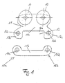
- Fig. 1 is an example of a tarpaulin roller used for moving sliding tarpaulins in curtainsiders.
- the invention is not limited to tarpaulin rollers, but generally includes support members for the storage of movable elements of a commercial vehicle body, the invention is particularly advantageous in tarpaulin rollers.
- the tarpaulin roller two rollers 10 (tandem roller) on. It is possible to equip the tarpaulin roller with only one roller or with more than two roles.
- a double tandem roller with four rollers is possible.
- the two rollers 10 are connected to a mounting plate 11 and rotatably supported.
- the two rollers 10 are arranged in a mounting position in the upper region of the mounting plate 11.
- the mounting plate 11 has an opening 12 in a lower position in the installed position.
- the opening 12 serves as in Fig. 2 shown for holding a belt loop 13, which is pulled through the opening 12.
- the opening 12 is arranged substantially horizontally and elongated, wherein the length of the opening 12 corresponds approximately to the width of the belt loop 13 and is slightly longer.
- the mounting plate 11 in the region of the opening 12 is divisible, in particular horizontally divisible. This means that the opening 12 in the split state ( Fig. 1 ) is accessible for removing or attaching the belt loop.
- this has an upper part 11a and a lower part 11b.
- the two rollers 10 are attached to the upper part 11a and protrude slightly beyond the circumference of the upper part 11a addition. Another arrangement of the rollers 10 or a single roller on the upper part 11a is possible.
- the lower part 11b forms together with the upper part 11a an opening 12 for the belt loop 13 (FIG. Fig. 2 ).
- the upper limit of the opening 12 in the installation position is formed by the upper part 11a and the lower boundary of the opening 12 through the lower part 11b.
- the upper part 11a has for this purpose an elongate, substantially in the vehicle longitudinal direction extending recess 12a, which is open at the bottom (in the disassembled state). Laterally, the recess 12a is bounded by two eye-shaped projections or two eyes, which extend in the installed position downwards. In the two eye-shaped projections 12b, 12c each have a bore 12d is provided, which serves for fastening of the lower part 11b.
- the lower part 11b extends parallel to the upper part 11a.
- two eyes 11c, 11d are provided with corresponding bores, which are in the assembled state with the two holes 12d of the eye-shaped projections 12b, 12c on the upper part 11a are aligned.
- the lower part is detachably connected by mechanical connecting means 19 with the upper part 11a.
- the connecting means 19 are rivets, in particular countersunk rivets, which are arranged in the bores of the eyes 11c, 11d or the bores 12d of the eye-shaped extensions 12b, 12c.
- Other mechanical connection means are possible.
- Fig. 2 It can also be seen that the lower part is arranged on the outer side of the tarpaulin roller in the installation position, so that the tarpaulin roller can be moved along the structure unhindered.
- the rollers 10 are attached to the inner side of the tarpaulin roller in the installation position and are in the mounted state of the tarpaulin roller in rails provided therefor, which are formed on the longitudinal beams of the structure (not shown).
- Another arrangement of the lower part 11b on the upper part 11a is possible, depending on the space requirement and execution of the longitudinal spar, in which the guide rail is designed for the scooter.
- the belt loop 13 passes through the opening 12 in the mounting plate 11 and is held securely in this.
- the belt loop 13 forms the end of a belt 13b, which is sewn to the side tarpaulin 13a.
- the side tarpaulin 13a or sliding tarpaulin over the belt 13b is securely connected to the mounting plate 11 of the tarpaulin roller.
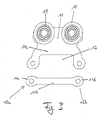
- FIGS. 3 to 6b Other embodiments, all based on the principle that the mounting plate 11 in the region of the opening 12 is divisible, are in the FIGS. 3 to 6b shown.
- the tarpaulin roller according to Fig. 3 As well as the tarpaulin scooter according to the FIGS. 1 . 2 a removable lower part, which is connected in the mounted state by mechanical connection means 19, in particular by riveting, with the upper part.
- the eyes 11c, 11d provided at the longitudinal ends 15a, 15b are formed to be axially symmetrical, whereas the eyes 11c, 11d are designed to be axially symmetrical Fig. 1 something upwards.
- the lower part according to Fig. 1 a U-shaped profile.
- the lower part according to Fig. 3 on the other hand has a bone-shaped profile.
- the tarpaulin roller according to Fig. 5 differs from the two plan scooters according to FIGS. 1 to 4 in that the lower part 11b is firmly connected to the upper part 11a. Specifically, the first longitudinal end 15a of the lower part 15b is fixedly connected to the upper part 11a. In this case, the lower part 11b and the upper part 11a in the region of the connection point form a curved connecting arm which delimits the opening 12 laterally. Another embodiment of the connection point is possible.
- the second other longitudinal end 15b of the lower part 11b, together with the upper part 11a, forms a gap 15c, which opens laterally into the opening 12.
- the gap 15c is like the opening 12 also arranged horizontally and forms an extension of the opening 12 in the horizontal direction.
- the opening for removing or for attaching the belt loop 13 is accessible.
- the lower part 11b is connected to the upper part 11a by a closure 14 which is arranged in the region of the second longitudinal end 15b of the lower part 11b.
- the closure 14 thus forms a lateral boundary of the opening 12, which is arranged opposite the connection point between the lower part 11b and the upper part 11a in the region of the first longitudinal end 15a.
- the closure is designed as a closure plate 14a, which connects the second (free) longitudinal end 15b of the lower part 11b with the upper part 11a.
- the connection of the closure plate with the lower part 11b and the upper part 11a takes place mechanically, for example by riveting 19th
- the closure plate 14a is designed so that it covers the eyes, in which the holes for the rivets 19 are provided, flush.
- FIGS. 6a, 6b are based on a similar principle as the embodiment according to Fig. 5 inasmuch as these likewise have respective lower parts 11b connected to the upper part 11a.
- connection of the lower part 11b on the upper part 11a is on the tarpaulin roller according to Fig. 5 directed.
- the lower part 11b is adapted so that it can be pivoted into an open position by the lower part 11b is bent to the side.
- the connection point in the region of the first longitudinal end 15a is designed accordingly. Due to the lateral bending of the lower part 11b, the locking elements 16 described below are decoupled, whereby the gap 15c is formed or enlarged, so that the opening 12 is easily accessible.
- the lower part 11 b is bent back so that this in the Fig. 6a, 6b shown position and latch the locking elements 16 and the upper part 11a and the lower part 11b are positively connected.
- the connection point can also be designed as a joint.
- the tarpaulin roller according to Fig. 6a differs from the tarpaulin scooter according to Fig. 5 further by the shape of the closure 14.
- the closure 14 according to Fig. 6a is designed as latching connection with locking elements 16.
- the latching elements 16 are arranged on the one hand on the lower part 11 b and on the other hand on the upper part 11 a and are in the closed position in engagement, as in Fig. 6a shown.
- the division in the region of the opening 12 takes place in accordance with the exemplary embodiment Fig. 6a in the vertical direction between an end surface of the lower part 11b and a projection 17 which is connected to the upper part 11a.
- the extension 17 forms the lateral boundary of the opening 12.
- the locking connection according to Fig. 6a a locking lug 16a, which is provided on the lower part 11b, in particular on the second free longitudinal end 15b of the lower part 11b.
- the locking lug 16a extends substantially in the horizontal direction and forms an extension of the lower part 11b.
- the detent 16a is associated with a detent opening 16b, which is formed in the extension 17 and the lower part 11b is open.
- latching elements 16 are formed so that the latching lug on the extension 17 and the latching opening in the lower part 11 b is formed. Another arrangement of the locking elements 16 is also possible.
- the tarpaulin roller according to Fig. 6b based on the tarpaulin scooter according to Fig. 6a and additionally has a securing means 18 which fixes the two locking elements 16 in the closed position.
- the securing means 18 is designed as a rivet, which is arranged in the region of the latching lug 16a and connects the lower part 11b with the upper part 11a. To open the locking connection, the rivet 18 is removed with a suitable tool, the latching connection is released and the lower part 11 b bent to the side. For mounting the lower part 11 b, after the belt loop is retracted, bent into the closed position until the latching connection locked, which is then secured by means of the rivet 18.
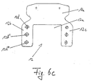
- FIG. 6c Another embodiment of a tarpaulin roller according to the invention is in Fig. 6c shown.
- This embodiment is based on the divisible tarpaulin roller according to Fig. 1 or according to Fig. 3 , This means that, as with the plan scooters according to FIGS. 1 . 3 the attachment plate 11 is completely divisible or divided in the region of the opening 12 such that the upper part 11a and the lower part 11b (in FIG Fig. 6c not shown) are separable from each other.
- the tarpaulin roller is suitable according to Fig. 6c also as a repair solution.
- the tarpaulin roller according to Fig. 6c yet another function and is designed so that the opening 12 is adjustable.
- the adjustability of the opening is achieved in that the two eye-shaped projections 12b, 12c are extended downward, ie in the vertical direction in the installed position.
- adjustment means 12 are provided for the adjustability of the opening, which in the embodiment according to Fig. 6c a plurality of superimposed holes 12d ', 12d'',12d'' include.
- the bores 12d ', 12d'',12d''' are provided symmetrically in both extensions 12b, 12c. In this case, the respectively associated holes in the extensions 12b, 12c are arranged at the same height or horizontally.
- Other adjusting means for example, vertically extending slots, in particular with different locking options, are conceivable.
- the eye-shaped extensions 12b, 12c extended such that at least two, in particular three or more holes 12d ', 12d'',12d''' are provided one above the other, in particular vertically one above the other.
- the extensions 12b, 12c limit laterally, as in the embodiments according to Fig. 1 . 3 the recess 12a and the opening 12th
- the lower part 11b (not shown) can be connected to the various holes 12d ', 12d' ', 12d' '' at different altitudes.
- the lower boundary of the opening 12 is adjustable in different positions, so that the height position of the belt loop 13 (not shown) which has passed through the opening 12 is adjustable.
- rollers in the tarpaulin roller according to Fig. 6c not shown for the sake of simplicity.
- the tarpaulin scooters according to the Figures 1 to 6b allow easy replacement without having to destroy the belt loop.
- no special repair scooters are required, which are riveted to the belt or with the side tarpaulin, but a uniform horizontally or vertically divisible tarpaulin roller is used, which can be replaced if necessary.
- the power transmission from the side tarp over the belt 13b on the tarpaulin roller is not affected by the interchangeability of the scooter.
- the tarpaulin roller according to Fig. 6c is also adaptable to different plans or tolerance deviations of tarpaulins, since the opening 12 of the tarpaulin roller is height adjustable.
- the invention also includes a commercial vehicle body and a utility vehicle with such a tarpaulin roller.
Landscapes
- Engineering & Computer Science (AREA)
- Mechanical Engineering (AREA)
- Tents Or Canopies (AREA)
- Automotive Seat Belt Assembly (AREA)
- Motorcycle And Bicycle Frame (AREA)
- Operating, Guiding And Securing Of Roll- Type Closing Members (AREA)
Priority Applications (1)
| Application Number | Priority Date | Filing Date | Title |
|---|---|---|---|
| PL09007243T PL2130704T3 (pl) | 2008-06-06 | 2009-05-29 | Element nośny do ruchomych elementów nadwozia pojazdu użytkowego i nadwozie pojazdu użytkowego z tego rodzaju elementem nośnym |
Applications Claiming Priority (2)
| Application Number | Priority Date | Filing Date | Title |
|---|---|---|---|
| DE202008007592 | 2008-06-06 | ||
| DE202008007930U DE202008007930U1 (de) | 2008-06-06 | 2008-06-13 | Trägerelement für bewegliche Elemente eines Nutzfahrzeugaufbaus und Nutzfahrzeugaufbau mit einem derartigen Trägerelement |
Publications (3)
| Publication Number | Publication Date |
|---|---|
| EP2130704A2 true EP2130704A2 (fr) | 2009-12-09 |
| EP2130704A3 EP2130704A3 (fr) | 2010-08-18 |
| EP2130704B1 EP2130704B1 (fr) | 2014-07-02 |
Family
ID=41254283
Family Applications (1)
| Application Number | Title | Priority Date | Filing Date |
|---|---|---|---|
| EP09007243.0A Active EP2130704B1 (fr) | 2008-06-06 | 2009-05-29 | Elément de support pour éléments mobiles d'une structure de véhicule utilitaire et structure de véhicule utilitaire dotée d'un tel élément de support |
Country Status (3)
| Country | Link |
|---|---|
| EP (1) | EP2130704B1 (fr) |
| DE (1) | DE202008007930U1 (fr) |
| PL (1) | PL2130704T3 (fr) |
Families Citing this family (1)
| Publication number | Priority date | Publication date | Assignee | Title |
|---|---|---|---|---|
| AU2014253657B2 (en) * | 2013-04-18 | 2017-08-31 | Mile STANKOVIC | Collision bearing |
Family Cites Families (6)
| Publication number | Priority date | Publication date | Assignee | Title |
|---|---|---|---|---|
| GB2093099B (en) * | 1981-02-12 | 1984-08-01 | Southfields Coachworks Ltd | Side curtain assembly for goods vehicles |
| DE4436238A1 (de) * | 1994-10-11 | 1996-04-18 | Miederhoff Franz Fa | Vorrichtung zur rollbaren Aufhängung insbesondere von Seitenspannplanen von Lkw-Aufbauten |
| DE19720525C2 (de) * | 1997-02-15 | 1999-10-28 | Schmitz Anhaenger Fahrzeugbau | Plane für Lastfahrzeuge |
| DE29815741U1 (de) * | 1998-09-01 | 2000-01-05 | Edscha LKW-Schiebeverdecke GmbH, 94491 Hengersberg | Seitenplanenaufhängung an Verdecken für Nutzfahrzeuge |
| DE20022003U1 (de) * | 2000-12-27 | 2001-05-10 | Roland International B.V., Tegelen | Verdeck aus Planen für ein Fahrzeug zur Beförderung von Lasten |
| FR2842464B1 (fr) * | 2002-07-17 | 2004-10-15 | Fair Internat | Latte de renfort pour paroi souple de vehicule du genre fourgon, procede d'elaboration d'une telle paroi lattee et paroi obtenue par le procede |
-
2008
- 2008-06-13 DE DE202008007930U patent/DE202008007930U1/de not_active Expired - Lifetime
-
2009
- 2009-05-29 EP EP09007243.0A patent/EP2130704B1/fr active Active
- 2009-05-29 PL PL09007243T patent/PL2130704T3/pl unknown
Non-Patent Citations (1)
| Title |
|---|
| None |
Also Published As
| Publication number | Publication date |
|---|---|
| PL2130704T3 (pl) | 2014-11-28 |
| DE202008007930U1 (de) | 2009-10-29 |
| EP2130704A3 (fr) | 2010-08-18 |
| EP2130704B1 (fr) | 2014-07-02 |
Similar Documents
| Publication | Publication Date | Title |
|---|---|---|
| EP2943376B1 (fr) | Barres de toit pour véhicule automobile | |
| EP1780354B1 (fr) | Agencement d'une porte coulissante de véhicule automobile | |
| DE2532187A1 (de) | Schiebedach fuer kraftfahrzeuge | |
| EP2736762B1 (fr) | Siège de véhicule, en particulier siège de véhicule à moteur | |
| DE60017190T2 (de) | Fahrzeugmontierter gepäckträger | |
| DE602005002201T2 (de) | Teleskopführung für Schubladen | |
| DE2936051C2 (de) | Hebevorrichtung für ein Kraftfahrzeug-Schiebedach | |
| EP0359962A1 (fr) | Siège, en particulier siège de véhicule automobile | |
| AT518211A2 (de) | Runge für einen nutzfahrzeug- oder anhängeraufbau | |
| DE10333781A1 (de) | Öffnungsfähiges Fahrzeugdach | |
| DE202020006041U1 (de) | Anordnung zur Führung einer Schiebetür oder Falt-Schiebetür | |
| DE102008008747A1 (de) | Schließsystem | |
| DE202021100270U1 (de) | Adaptersystem zum lösbaren Ankoppeln von Zubehör an einem Fahrzeug-Gepäckträger | |
| WO2020173990A1 (fr) | Toit ouvrant de véhicule à panneau de fermeture | |
| DE102017204494B4 (de) | Schiebedachsystem für ein Kraftfahrzeug | |
| EP2130704B1 (fr) | Elément de support pour éléments mobiles d'une structure de véhicule utilitaire et structure de véhicule utilitaire dotée d'un tel élément de support | |
| DE102010043022A1 (de) | Sicherungsvorrichtung für ein Kraftfahrzeug | |
| EP0383003A2 (fr) | Dispositif d'arrêt pour les vantaux de fenêtres, portes ou de choses pareilles | |
| DE10254774B4 (de) | Fahrzeugdach | |
| DE19719644C2 (de) | Windabweiseranordnung für ein Fahrzeugdach | |
| DE102017117042A1 (de) | Verschlussvorrichtung mit Verstellhebel | |
| EP1764138A1 (fr) | Appareil pour positionner une fixation comprenant deux parties sur un ski | |
| DE60304742T2 (de) | Spannungsvorrichtung für ein öffnungsfähiges dach eines kraftfahrzeugs | |
| DE102006061505B4 (de) | Rolloeinheit sowie korrespondierende Tragvorrichtung | |
| DE2249718C3 (de) | Schiebedach für Kraftfahrzeuge |
Legal Events
| Date | Code | Title | Description |
|---|---|---|---|
| PUAI | Public reference made under article 153(3) epc to a published international application that has entered the european phase |
Free format text: ORIGINAL CODE: 0009012 |
|
| AK | Designated contracting states |
Kind code of ref document: A2 Designated state(s): AT BE BG CH CY CZ DE DK EE ES FI FR GB GR HR HU IE IS IT LI LT LU LV MC MK MT NL NO PL PT RO SE SI SK TR |
|
| PUAL | Search report despatched |
Free format text: ORIGINAL CODE: 0009013 |
|
| AK | Designated contracting states |
Kind code of ref document: A3 Designated state(s): AT BE BG CH CY CZ DE DK EE ES FI FR GB GR HR HU IE IS IT LI LT LU LV MC MK MT NL NO PL PT RO SE SI SK TR |
|
| AX | Request for extension of the european patent |
Extension state: AL BA RS |
|
| 19U | Interruption of proceedings before grant |
Effective date: 20091030 |
|
| 19W | Proceedings resumed before grant after interruption of proceedings |
Effective date: 20101201 |
|
| 17P | Request for examination filed |
Effective date: 20110203 |
|
| RAP1 | Party data changed (applicant data changed or rights of an application transferred) |
Owner name: KOEGEL TRAILER GMBH & CO. KG |
|
| RAP1 | Party data changed (applicant data changed or rights of an application transferred) |
Owner name: KOEGEL TRAILER GMBH & CO. KG |
|
| 17Q | First examination report despatched |
Effective date: 20120703 |
|
| GRAP | Despatch of communication of intention to grant a patent |
Free format text: ORIGINAL CODE: EPIDOSNIGR1 |
|
| INTG | Intention to grant announced |
Effective date: 20131211 |
|
| GRAP | Despatch of communication of intention to grant a patent |
Free format text: ORIGINAL CODE: EPIDOSNIGR1 |
|
| GRAS | Grant fee paid |
Free format text: ORIGINAL CODE: EPIDOSNIGR3 |
|
| INTG | Intention to grant announced |
Effective date: 20140506 |
|
| GRAA | (expected) grant |
Free format text: ORIGINAL CODE: 0009210 |
|
| AK | Designated contracting states |
Kind code of ref document: B1 Designated state(s): AT BE BG CH CY CZ DE DK EE ES FI FR GB GR HR HU IE IS IT LI LT LU LV MC MK MT NL NO PL PT RO SE SI SK TR |
|
| REG | Reference to a national code |
Ref country code: GB Ref legal event code: FG4D Free format text: NOT ENGLISH |
|
| REG | Reference to a national code |
Ref country code: CH Ref legal event code: EP Ref country code: AT Ref legal event code: REF Ref document number: 675713 Country of ref document: AT Kind code of ref document: T Effective date: 20140715 |
|
| REG | Reference to a national code |
Ref country code: IE Ref legal event code: FG4D Free format text: LANGUAGE OF EP DOCUMENT: GERMAN |
|
| REG | Reference to a national code |
Ref country code: DE Ref legal event code: R096 Ref document number: 502009009596 Country of ref document: DE Effective date: 20140814 |
|
| REG | Reference to a national code |
Ref country code: NL Ref legal event code: T3 |
|
| REG | Reference to a national code |
Ref country code: PL Ref legal event code: T3 |
|
| REG | Reference to a national code |
Ref country code: LT Ref legal event code: MG4D |
|
| PG25 | Lapsed in a contracting state [announced via postgrant information from national office to epo] |
Ref country code: ES Free format text: LAPSE BECAUSE OF FAILURE TO SUBMIT A TRANSLATION OF THE DESCRIPTION OR TO PAY THE FEE WITHIN THE PRESCRIBED TIME-LIMIT Effective date: 20140702 Ref country code: PT Free format text: LAPSE BECAUSE OF FAILURE TO SUBMIT A TRANSLATION OF THE DESCRIPTION OR TO PAY THE FEE WITHIN THE PRESCRIBED TIME-LIMIT Effective date: 20141103 Ref country code: NO Free format text: LAPSE BECAUSE OF FAILURE TO SUBMIT A TRANSLATION OF THE DESCRIPTION OR TO PAY THE FEE WITHIN THE PRESCRIBED TIME-LIMIT Effective date: 20141002 Ref country code: FI Free format text: LAPSE BECAUSE OF FAILURE TO SUBMIT A TRANSLATION OF THE DESCRIPTION OR TO PAY THE FEE WITHIN THE PRESCRIBED TIME-LIMIT Effective date: 20140702 Ref country code: BG Free format text: LAPSE BECAUSE OF FAILURE TO SUBMIT A TRANSLATION OF THE DESCRIPTION OR TO PAY THE FEE WITHIN THE PRESCRIBED TIME-LIMIT Effective date: 20141002 Ref country code: LT Free format text: LAPSE BECAUSE OF FAILURE TO SUBMIT A TRANSLATION OF THE DESCRIPTION OR TO PAY THE FEE WITHIN THE PRESCRIBED TIME-LIMIT Effective date: 20140702 Ref country code: GR Free format text: LAPSE BECAUSE OF FAILURE TO SUBMIT A TRANSLATION OF THE DESCRIPTION OR TO PAY THE FEE WITHIN THE PRESCRIBED TIME-LIMIT Effective date: 20141003 Ref country code: SE Free format text: LAPSE BECAUSE OF FAILURE TO SUBMIT A TRANSLATION OF THE DESCRIPTION OR TO PAY THE FEE WITHIN THE PRESCRIBED TIME-LIMIT Effective date: 20140702 |
|
| PG25 | Lapsed in a contracting state [announced via postgrant information from national office to epo] |
Ref country code: CY Free format text: LAPSE BECAUSE OF FAILURE TO SUBMIT A TRANSLATION OF THE DESCRIPTION OR TO PAY THE FEE WITHIN THE PRESCRIBED TIME-LIMIT Effective date: 20140702 Ref country code: HR Free format text: LAPSE BECAUSE OF FAILURE TO SUBMIT A TRANSLATION OF THE DESCRIPTION OR TO PAY THE FEE WITHIN THE PRESCRIBED TIME-LIMIT Effective date: 20140702 Ref country code: LV Free format text: LAPSE BECAUSE OF FAILURE TO SUBMIT A TRANSLATION OF THE DESCRIPTION OR TO PAY THE FEE WITHIN THE PRESCRIBED TIME-LIMIT Effective date: 20140702 Ref country code: IS Free format text: LAPSE BECAUSE OF FAILURE TO SUBMIT A TRANSLATION OF THE DESCRIPTION OR TO PAY THE FEE WITHIN THE PRESCRIBED TIME-LIMIT Effective date: 20141102 |
|
| REG | Reference to a national code |
Ref country code: DE Ref legal event code: R097 Ref document number: 502009009596 Country of ref document: DE |
|
| PG25 | Lapsed in a contracting state [announced via postgrant information from national office to epo] |
Ref country code: EE Free format text: LAPSE BECAUSE OF FAILURE TO SUBMIT A TRANSLATION OF THE DESCRIPTION OR TO PAY THE FEE WITHIN THE PRESCRIBED TIME-LIMIT Effective date: 20140702 Ref country code: SK Free format text: LAPSE BECAUSE OF FAILURE TO SUBMIT A TRANSLATION OF THE DESCRIPTION OR TO PAY THE FEE WITHIN THE PRESCRIBED TIME-LIMIT Effective date: 20140702 Ref country code: IT Free format text: LAPSE BECAUSE OF FAILURE TO SUBMIT A TRANSLATION OF THE DESCRIPTION OR TO PAY THE FEE WITHIN THE PRESCRIBED TIME-LIMIT Effective date: 20140702 Ref country code: DK Free format text: LAPSE BECAUSE OF FAILURE TO SUBMIT A TRANSLATION OF THE DESCRIPTION OR TO PAY THE FEE WITHIN THE PRESCRIBED TIME-LIMIT Effective date: 20140702 Ref country code: RO Free format text: LAPSE BECAUSE OF FAILURE TO SUBMIT A TRANSLATION OF THE DESCRIPTION OR TO PAY THE FEE WITHIN THE PRESCRIBED TIME-LIMIT Effective date: 20140702 |
|
| PLBE | No opposition filed within time limit |
Free format text: ORIGINAL CODE: 0009261 |
|
| STAA | Information on the status of an ep patent application or granted ep patent |
Free format text: STATUS: NO OPPOSITION FILED WITHIN TIME LIMIT |
|
| 26N | No opposition filed |
Effective date: 20150407 |
|
| PG25 | Lapsed in a contracting state [announced via postgrant information from national office to epo] |
Ref country code: SI Free format text: LAPSE BECAUSE OF FAILURE TO SUBMIT A TRANSLATION OF THE DESCRIPTION OR TO PAY THE FEE WITHIN THE PRESCRIBED TIME-LIMIT Effective date: 20140702 |
|
| REG | Reference to a national code |
Ref country code: CH Ref legal event code: PL |
|
| GBPC | Gb: european patent ceased through non-payment of renewal fee |
Effective date: 20150529 |
|
| PG25 | Lapsed in a contracting state [announced via postgrant information from national office to epo] |
Ref country code: LU Free format text: LAPSE BECAUSE OF FAILURE TO SUBMIT A TRANSLATION OF THE DESCRIPTION OR TO PAY THE FEE WITHIN THE PRESCRIBED TIME-LIMIT Effective date: 20150529 Ref country code: LI Free format text: LAPSE BECAUSE OF NON-PAYMENT OF DUE FEES Effective date: 20150531 Ref country code: MC Free format text: LAPSE BECAUSE OF FAILURE TO SUBMIT A TRANSLATION OF THE DESCRIPTION OR TO PAY THE FEE WITHIN THE PRESCRIBED TIME-LIMIT Effective date: 20140702 Ref country code: CH Free format text: LAPSE BECAUSE OF NON-PAYMENT OF DUE FEES Effective date: 20150531 |
|
| REG | Reference to a national code |
Ref country code: IE Ref legal event code: MM4A |
|
| PG25 | Lapsed in a contracting state [announced via postgrant information from national office to epo] |
Ref country code: GB Free format text: LAPSE BECAUSE OF NON-PAYMENT OF DUE FEES Effective date: 20150529 Ref country code: IE Free format text: LAPSE BECAUSE OF NON-PAYMENT OF DUE FEES Effective date: 20150529 |
|
| REG | Reference to a national code |
Ref country code: FR Ref legal event code: PLFP Year of fee payment: 8 |
|
| PG25 | Lapsed in a contracting state [announced via postgrant information from national office to epo] |
Ref country code: MT Free format text: LAPSE BECAUSE OF FAILURE TO SUBMIT A TRANSLATION OF THE DESCRIPTION OR TO PAY THE FEE WITHIN THE PRESCRIBED TIME-LIMIT Effective date: 20140702 |
|
| REG | Reference to a national code |
Ref country code: FR Ref legal event code: PLFP Year of fee payment: 9 |
|
| PG25 | Lapsed in a contracting state [announced via postgrant information from national office to epo] |
Ref country code: HU Free format text: LAPSE BECAUSE OF FAILURE TO SUBMIT A TRANSLATION OF THE DESCRIPTION OR TO PAY THE FEE WITHIN THE PRESCRIBED TIME-LIMIT; INVALID AB INITIO Effective date: 20090529 |
|
| PG25 | Lapsed in a contracting state [announced via postgrant information from national office to epo] |
Ref country code: BE Free format text: LAPSE BECAUSE OF NON-PAYMENT OF DUE FEES Effective date: 20150531 |
|
| REG | Reference to a national code |
Ref country code: FR Ref legal event code: PLFP Year of fee payment: 10 |
|
| PG25 | Lapsed in a contracting state [announced via postgrant information from national office to epo] |
Ref country code: MK Free format text: LAPSE BECAUSE OF FAILURE TO SUBMIT A TRANSLATION OF THE DESCRIPTION OR TO PAY THE FEE WITHIN THE PRESCRIBED TIME-LIMIT Effective date: 20140702 |
|
| REG | Reference to a national code |
Ref country code: DE Ref legal event code: R082 Ref document number: 502009009596 Country of ref document: DE Representative=s name: MEISSNER BOLTE PATENTANWAELTE RECHTSANWAELTE P, DE Ref country code: DE Ref legal event code: R081 Ref document number: 502009009596 Country of ref document: DE Owner name: KOEGEL TRAILER GMBH, DE Free format text: FORMER OWNER: KOEGEL TRAILER GMBH & CO. KG, 89349 BURTENBACH, DE |
|
| REG | Reference to a national code |
Ref country code: GB Ref legal event code: 732E Free format text: REGISTERED BETWEEN 20200917 AND 20200923 |
|
| REG | Reference to a national code |
Ref country code: AT Ref legal event code: PC Ref document number: 675713 Country of ref document: AT Kind code of ref document: T Owner name: KOEGEL TRAILER GMBH, DE Effective date: 20200831 |
|
| REG | Reference to a national code |
Ref country code: NL Ref legal event code: PD Owner name: KOEGEL TRAILER GMBH; DE Free format text: DETAILS ASSIGNMENT: CHANGE OF OWNER(S), ASSIGNMENT; FORMER OWNER NAME: KOEGEL TRAILER GMBH & CO. KG Effective date: 20201217 |
|
| PGFP | Annual fee paid to national office [announced via postgrant information from national office to epo] |
Ref country code: NL Payment date: 20250526 Year of fee payment: 17 |
|
| PGFP | Annual fee paid to national office [announced via postgrant information from national office to epo] |
Ref country code: PL Payment date: 20250509 Year of fee payment: 17 |
|
| PGFP | Annual fee paid to national office [announced via postgrant information from national office to epo] |
Ref country code: FR Payment date: 20250526 Year of fee payment: 17 |
|
| PGFP | Annual fee paid to national office [announced via postgrant information from national office to epo] |
Ref country code: AT Payment date: 20250520 Year of fee payment: 17 |
|
| PGFP | Annual fee paid to national office [announced via postgrant information from national office to epo] |
Ref country code: TR Payment date: 20250509 Year of fee payment: 17 |
|
| PGFP | Annual fee paid to national office [announced via postgrant information from national office to epo] |
Ref country code: CZ Payment date: 20250520 Year of fee payment: 17 |
|
| PGFP | Annual fee paid to national office [announced via postgrant information from national office to epo] |
Ref country code: DE Payment date: 20260529 Year of fee payment: 18 |